ALTE DOCUMENTE
|
|||||||||
|
|
|
|
|||||
|
|
|
Overview |
|||||
Shared Ethernet works extremely well under ideal conditions. If the number of devices that try to access the network is low, the number of collisions stays well within acceptable limits. However, when the number of users on the network increases, the number of collisions can significantly reduce performance. Bridges were developed to help correct performance problems that arose from increased collisions. Switches evolved from bridges to become the main technology in modern Ethernet LANs.
Collisions and broadcasts are expected events in modern networks. They are engineered into the design of Ethernet and higher layer technologies. However, when collisions and broadcasts occur in numbers that are above the optimum, network performance suffers. Collision domains and broadcast domains should be designed to limit the negative effects of collisions and broadcasts. This module explores the effects of collisions and broadcasts on network traffic and then describes how bridges and routers are used to segment networks for improved performance.
This
module covers some of the objectives for the CCNA 640-801, INTRO 640-821, and
ICND 640-811 exams. ![]()
![]()
![]()
Students
who complete this module should be able to perform the following tasks: ![]()
Explain network segmentation and list the devices used to create segments
|
|
|
|
This page will discuss the operation of Layer 2 bridges.
As more nodes are added to an Ethernet segment, use of the media increases. Ethernet is a shared media, which means only one node can transmit data at a time. The addition of more nodes increases the demands on the available bandwidth and places additional loads on the media. This also increases the probability of collisions, which results in more retransmissions. A solution to the problem is to break the large segment into p 555g64f arts and separate it into isolated collision domains.
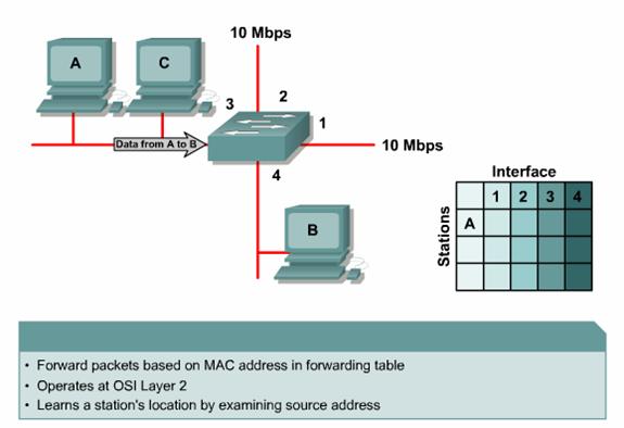
To
accomplish this a bridge keeps a table of MAC
addresses and the associated ports. The bridge then forwards or discards frames
based on the table entries. The following steps illustrate the operation of a
bridge: ![]()
These are the steps that a bridge uses to forward and discard frames that are received on any of its ports.
|
|
|
|
Generally,
a bridge has only two ports and divides a collision domain into two parts. All
decisions made by a bridge are based on MAC or Layer 2 addresses and do not
affect the logical or Layer 3 addresses. A bridge will divide a collision
domain but has no effect on a logical or broadcast domain. If a network does
not have a device that works with Layer 3 addresses, such as a router, the
entire network will share the same logical broadcast address space. A bridge
will create more collision domains but will not add broadcast domains. ![]()
A
switch is essentially a fast, multi-port bridge that can contain dozens of
ports. Each port creates its own collision domain. In a network of 20 nodes, 20
collision domains exist if each node is plugged into its own switch port. If an
uplink port is included, one switch creates 21 single-node collision domains. A
switch dynamically builds and maintains a content-addressable memory (
|
|
|
|
A
switch is simply a bridge with many ports. When only one node is connected to a
switch port, the collision domain on the shared media contains only two nodes.
The two nodes in this small segment, or collision domain, consist of the switch
port and the host connected to it. These small physical segments are called
microsegments. ![]() Another capability
emerges when only two nodes are connected. In a network that uses twisted-pair
cabling, one pair is used to carry the transmitted signal from one node to the
other node. A separate pair is used for the return or received signal. It is
possible for signals to pass through both pairs simultaneously. The ability to
communicate in both directions at once is known as full duplex.
Another capability
emerges when only two nodes are connected. In a network that uses twisted-pair
cabling, one pair is used to carry the transmitted signal from one node to the
other node. A separate pair is used for the return or received signal. It is
possible for signals to pass through both pairs simultaneously. The ability to
communicate in both directions at once is known as full duplex. ![]() Most switches are
capable of supporting full duplex, as are most NICs. In full duplex mode, there
is no contention for the media. A collision domain no longer exists. In theory,
the bandwidth is doubled when full duplex is used.
Most switches are
capable of supporting full duplex, as are most NICs. In full duplex mode, there
is no contention for the media. A collision domain no longer exists. In theory,
the bandwidth is doubled when full duplex is used.
In
addition to faster microprocessors and memory, two other technological advances
made switches possible.
|
|
|
|
Latency
is the delay between the time a frame begins to leave the source device and
when the first part of the frame reaches its destination. ![]() A variety of
conditions can cause delays:
A variety of
conditions can cause delays:
|
|
|
|
How
a frame is switched to the destination port is a trade off between latency and
reliability. A switch can start to transfer the frame as soon as the
destination MAC address is received. This is called cut-through packet
switching and results in the lowest latency through the switch. ![]() However, no error
checking is available. The switch can also receive the entire frame before it
is sent to the destination port. This gives the switch software an opportunity
to verify the Frame Check Sequence (FCS). If the frame is invalid, it is discarded
at the switch. Since the entire frame is stored before it is forwarded, this is
called store-and-forward packet switching.
However, no error
checking is available. The switch can also receive the entire frame before it
is sent to the destination port. This gives the switch software an opportunity
to verify the Frame Check Sequence (FCS). If the frame is invalid, it is discarded
at the switch. Since the entire frame is stored before it is forwarded, this is
called store-and-forward packet switching. ![]() A compromise
between cut-through and store-and-forward packet switching is the fragment-free
mode. Fragment-free packet switching reads the first 64 bytes, which includes
the frame header, and starts to send out the packet before the entire data
field and checksum are read. This mode verifies the reliability of the
addresses and LLC protocol information to ensure the data will be handled
properly and arrive at the correct destination.
A compromise
between cut-through and store-and-forward packet switching is the fragment-free
mode. Fragment-free packet switching reads the first 64 bytes, which includes
the frame header, and starts to send out the packet before the entire data
field and checksum are read. This mode verifies the reliability of the
addresses and LLC protocol information to ensure the data will be handled
properly and arrive at the correct destination.
When cut-through packet switching is used, the source and destination ports must have the same bit rate to keep the frame intact. This is called symmetric switching. If the bit rates are not the same, the frame must be stored at one bit rate before it is sent out at the other bit rate. This is known as asymmetric switching. Store-and-forward mode must be used for asymmetric switching.
Asymmetric switching provides switched connections between ports with different bandwidths. Asymmetric switching is optimized for client/server traffic flows in which multiple clients communicate with a server at once. More bandwidth must be dedicated to the server port to prevent a bottleneck.
The Interactive Media Activity will help students become familiar with the three types of switch modes.
|
|
|
|
When
multiple switches are arranged in a simple hierarchical tree, switching loops
are unlikely to occur. However, switched networks are often designed with
redundant paths to provide for reliability and fault tolerance. ![]() Redundant paths
are desirable but they can have undesirable side effects such as switching
loops. Switching loops are one such side effect. Switching loops can occur by
design or by accident, and they can lead to broadcast storms that will rapidly
overwhelm a network. STP is a standards-based routing protocol that is used to
avoid routing loops. Each switch in a LAN that uses STP sends messages called
Bridge Protocol Data Units (BPDUs) out all its ports to let other switches know
of its existence. This information is used to elect a root bridge for the
network. The switches use the spanning-tree algorithm (STA) to resolve and shut
down the redundant paths.
Redundant paths
are desirable but they can have undesirable side effects such as switching
loops. Switching loops are one such side effect. Switching loops can occur by
design or by accident, and they can lead to broadcast storms that will rapidly
overwhelm a network. STP is a standards-based routing protocol that is used to
avoid routing loops. Each switch in a LAN that uses STP sends messages called
Bridge Protocol Data Units (BPDUs) out all its ports to let other switches know
of its existence. This information is used to elect a root bridge for the
network. The switches use the spanning-tree algorithm (STA) to resolve and shut
down the redundant paths.
Each
port on a switch that uses STP exists in one of the following five states: ![]()
A port moves through these five states as follows:
STP is used to create a logical hierarchical tree with no loops. However, the alternate paths are still available if necessary.
The Interactive Media Activity will help students learn the function of each spanning-tree state.
|
|
|
|
|||
|
|
|
|
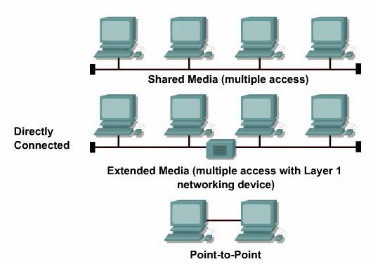
Here
are some examples of shared media and directly connected networks: ![]()
Collisions only occur in a shared environment. A highway system is an example of a shared environment in which collisions can occur because multiple vehicles use the same roads. As more vehicles enter the system, collisions become more likely. A shared data network is much like a highway. Rules exist to determine who has access to the network medium. However, sometimes the rules cannot handle the traffic load and collisions occur.
|
|
|
|
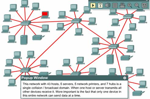
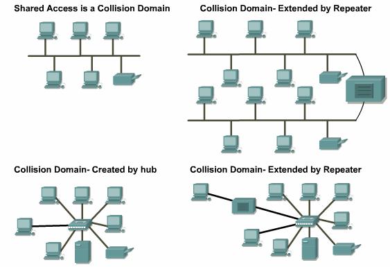
Collision
domains are the connected physical network segments where collisions can occur.
![]() Collisions cause
the network to be inefficient. Every time a collision happens on a network, all
transmission stops for a period of time. The length of this period of time
varies and is determined by a backoff algorithm for each network device.
Collisions cause
the network to be inefficient. Every time a collision happens on a network, all
transmission stops for a period of time. The length of this period of time
varies and is determined by a backoff algorithm for each network device.
The
types of devices that interconnect the media segments define collision domains.
![]() These devices have
been classified as OSI Layer 1, 2 or 3 devices. Layer 2 and Layer 3 devices
break up collision domains. This process is also known as segmentation.
These devices have
been classified as OSI Layer 1, 2 or 3 devices. Layer 2 and Layer 3 devices
break up collision domains. This process is also known as segmentation.
Layer
1 devices such as repeaters and hubs are mainly used to extend the Ethernet
cable segments. ![]() This allows more
hosts to be added. However, every host that is added increases the amount of
potential traffic on the network. Layer 1 devices forward all data that is sent
on the media. As more traffic is transmitted within a collision domain,
collisions become more likely. This results in diminished network performance,
which will be even more pronounced if all the computers use large amounts of
bandwidth. Layer 1 devices can cause the length of a LAN to be overextended and
result in collisions.
This allows more
hosts to be added. However, every host that is added increases the amount of
potential traffic on the network. Layer 1 devices forward all data that is sent
on the media. As more traffic is transmitted within a collision domain,
collisions become more likely. This results in diminished network performance,
which will be even more pronounced if all the computers use large amounts of
bandwidth. Layer 1 devices can cause the length of a LAN to be overextended and
result in collisions.
The
four repeater rule in Ethernet states that no more than four repeaters or
repeating hubs can be between any two computers on the network. ![]() For a repeated
10BASE-T network to function properly, the round-trip delay calculation must be
within certain limits. This ensures that all the workstations will be able to
hear all the collisions on the network. Repeater latency, propagation delay,
and NIC latency all contribute to the four repeater rule.
For a repeated
10BASE-T network to function properly, the round-trip delay calculation must be
within certain limits. This ensures that all the workstations will be able to
hear all the collisions on the network. Repeater latency, propagation delay,
and NIC latency all contribute to the four repeater rule. ![]() If the four
repeater rule is violated, the maximum delay limit may be exceeded. A late
collision is when a collision happens after the first 64 bytes of the frame are
transmitted. The chipsets in NICs are not required to retransmit automatically
when a late collision occurs. These late collision frames add delay that is
referred to as consumption delay. As consumption delay and latency increase,
network performance decreases.
If the four
repeater rule is violated, the maximum delay limit may be exceeded. A late
collision is when a collision happens after the first 64 bytes of the frame are
transmitted. The chipsets in NICs are not required to retransmit automatically
when a late collision occurs. These late collision frames add delay that is
referred to as consumption delay. As consumption delay and latency increase,
network performance decreases.
The 5-4-3-2-1 rule requires that the following guidelines should not be exceeded:
The 5-4-3-2-1 rule also provides guidelines to keep round-trip delay time within acceptable limits.
|
|
|
|
The
history of how Ethernet handles collisions and collision domains dates back to
research at the
One
important skill for a networking professional is the ability to recognize
collision domains. ![]() A collision domain
is created when several computers are connected to a single shared-access
medium that is not attached to other network devices. This situation limits the
number of computers that can use the segment. Layer 1 devices extend but do not
control collision domains.
A collision domain
is created when several computers are connected to a single shared-access
medium that is not attached to other network devices. This situation limits the
number of computers that can use the segment. Layer 1 devices extend but do not
control collision domains.
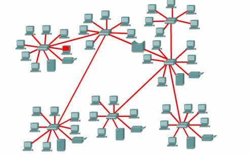
Layer
2 devices segment or divide collision domains. ![]() They use the MAC
address assigned to every Ethernet device to control frame propagation. Layer 2
devices are bridges and switches. They keep track of the MAC addresses and
their segments. This allows these devices to control the flow of traffic at the
Layer 2 level. This function makes networks more efficient. It allows data to
be transmitted on different segments of the LAN at the same time without
collisions. Bridges and switches divide collision domains into smaller parts.
Each part becomes its own collision domain.
They use the MAC
address assigned to every Ethernet device to control frame propagation. Layer 2
devices are bridges and switches. They keep track of the MAC addresses and
their segments. This allows these devices to control the flow of traffic at the
Layer 2 level. This function makes networks more efficient. It allows data to
be transmitted on different segments of the LAN at the same time without
collisions. Bridges and switches divide collision domains into smaller parts.
Each part becomes its own collision domain.
These
smaller collision domains will have fewer hosts and less traffic than the
original domain. ![]() The fewer hosts
that exist in a collision domain, the more likely the media will be available.
If the traffic between bridged segments is not too heavy a bridged network
works well. Otherwise, the Layer 2 device can slow down communication and
become a bottleneck.
The fewer hosts
that exist in a collision domain, the more likely the media will be available.
If the traffic between bridged segments is not too heavy a bridged network
works well. Otherwise, the Layer 2 device can slow down communication and
become a bottleneck.
Layer 2 and 3 devices do not forward collisions. Layer 3 devices divide collision domains into smaller domains.
Layer 3 devices also perform other functions. These functions will be covered in the section on broadcast domains.
The Interactive Media Activity will teach students about network segmentation.
|
|
|
|
To
communicate with all collision domains, protocols use broadcast and multicast
frames at Layer 2 of the OSI model. ![]() When a node needs
to communicate with all hosts on the network, it sends a broadcast frame with a
destination MAC address 0xFFFFFFFFFFFF. This is an address to which the NIC of
every host must respond.
When a node needs
to communicate with all hosts on the network, it sends a broadcast frame with a
destination MAC address 0xFFFFFFFFFFFF. This is an address to which the NIC of
every host must respond.
Layer 2 devices must flood all broadcast and multicast traffic. The accumulation of broadcast and multicast traffic from each device in the network is referred to as broadcast radiation. In some cases, the circulation of broadcast radiation can saturate the network so that there is no bandwidth left for application data. In this case, new network connections cannot be made and established connections may be dropped. This situation is called a broadcast storm. The probability of broadcast storms increases as the switched network grows.
A
NIC must rely on the CPU to process each broadcast or multicast group it
belongs to. Therefore, broadcast radiation affects the performance of hosts in
the network. Figure ![]() shows the results
of tests that Cisco conducted on the effect of broadcast radiation on the CPU
performance of a Sun SPARCstation 2 with a standard built-in Ethernet card. The
results indicate that an IP workstation can be effectively shut down by broadcasts
that flood the network. Although extreme, broadcast peaks of thousands of
broadcasts per second have been observed during broadcast storms. Tests in a
controlled environment with a range of broadcasts and multicasts on the network
show measurable system degradation with as few as 100 broadcasts or multicasts
per second.
shows the results
of tests that Cisco conducted on the effect of broadcast radiation on the CPU
performance of a Sun SPARCstation 2 with a standard built-in Ethernet card. The
results indicate that an IP workstation can be effectively shut down by broadcasts
that flood the network. Although extreme, broadcast peaks of thousands of
broadcasts per second have been observed during broadcast storms. Tests in a
controlled environment with a range of broadcasts and multicasts on the network
show measurable system degradation with as few as 100 broadcasts or multicasts
per second.
A host does not usually benefit if it processes a broadcast when it is not the intended destination. The host is not interested in the service that is advertised. High levels of broadcast radiation can noticeably degrade host performance. The three sources of broadcasts and multicasts in IP networks are workstations, routers, and multicast applications.
Workstations
broadcast an Address Resolution Protocol (ARP) request every time they need to
locate a MAC address that is not in the ARP table. ![]() Although the numbers
in the figure might appear low, they represent an average, well-designed IP
network. When broadcast and multicast traffic peak due
to storm behavior, peak CPU loss can be much higher than average.
Broadcast storms can be caused by a device that requests information from a
network that has grown too large. So many responses are sent to the original
request that the device cannot process them, or the first request triggers
similar requests from other devices that effectively block normal traffic flow on
the network.
Although the numbers
in the figure might appear low, they represent an average, well-designed IP
network. When broadcast and multicast traffic peak due
to storm behavior, peak CPU loss can be much higher than average.
Broadcast storms can be caused by a device that requests information from a
network that has grown too large. So many responses are sent to the original
request that the device cannot process them, or the first request triggers
similar requests from other devices that effectively block normal traffic flow on
the network.
As an example, the command telnet mumble.com translates into an IP address through a Domain Name System (DNS) search. An ARP request is broadcast to locate the MAC address. Generally, IP workstations cache 10 to 100 addresses in their ARP tables for about 2 hours. The ARP rate for a typical workstation might be about 50 addresses every 2 hours or 0.007 ARPs per second. Therefore, 2000 IP end stations will produce about 14 ARPs per second.
The routing protocols that are configured on a network can increase broadcast traffic significantly. Some administrators configure all workstations to run Routing Information Protocol (RIP) as a redundancy and reachability policy. Every 30 seconds, RIPv1 uses broadcasts to retransmit the entire RIP routing table to other RIP routers. If 2000 workstations were configured to run RIP and, on average, 50 packets were required to transmit the routing table, the workstations would generate 3333 broadcasts per second. Most network administrators only configure RIP on five to ten routers. For a routing table that has a size of 50 packets, 10 RIP routers would generate about 16 broadcasts per second.
IP multicast applications can adversely affect the performance of large, scaled, switched networks. Multicasting is an efficient way to send a stream of multimedia data to many users on a shared-media hub. However, it affects every user on a flat switched network. A packet video application could generate a 7-MB stream of multicast data that would be sent to every segment. This would result in severe congestion.
|
|
|
|
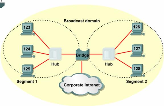
A
broadcast domain is a group of collision domains that are connected by Layer 2
devices. ![]() When a LAN is
broken up into multiple collision domains, each host in the network has more
opportunities to gain access to the media. This reduces the chance of
collisions and increases available bandwidth for every host. Broadcasts are
forwarded by Layer 2 devices. Excessive broadcasts can reduce the efficiency of
the entire LAN. Broadcasts have to be controlled at Layer 3 since Layers 1 and
2 devices cannot control them. A broadcast domain includes all of the collision
domains that process the same broadcast frame. This includes all the nodes that
are part of the network segment bounded by a Layer 3 device. Broadcast domains
are controlled at Layer 3 because routers do not forward
broadcasts. Routers actually work at Layers 1, 2, and 3. Like all Layer 1
devices, routers have a physical connection and transmit data onto the media. Routers
also have a Layer 2 encapsulation on all interfaces and perform the same
functions as other Layer 2 devices. Layer 3 allows routers to segment broadcast
domains.
When a LAN is
broken up into multiple collision domains, each host in the network has more
opportunities to gain access to the media. This reduces the chance of
collisions and increases available bandwidth for every host. Broadcasts are
forwarded by Layer 2 devices. Excessive broadcasts can reduce the efficiency of
the entire LAN. Broadcasts have to be controlled at Layer 3 since Layers 1 and
2 devices cannot control them. A broadcast domain includes all of the collision
domains that process the same broadcast frame. This includes all the nodes that
are part of the network segment bounded by a Layer 3 device. Broadcast domains
are controlled at Layer 3 because routers do not forward
broadcasts. Routers actually work at Layers 1, 2, and 3. Like all Layer 1
devices, routers have a physical connection and transmit data onto the media. Routers
also have a Layer 2 encapsulation on all interfaces and perform the same
functions as other Layer 2 devices. Layer 3 allows routers to segment broadcast
domains.
In order for a packet to be forwarded through a router it must have already been processed by a Layer 2 device and the frame information stripped off. Layer 3 forwarding is based on the destination IP address and not the MAC address. For a packet to be forwarded it must contain an IP address that is outside of the range of addresses assigned to the LAN and the router must have a destination to send the specific packet to in its routing table.
|
|
|
|
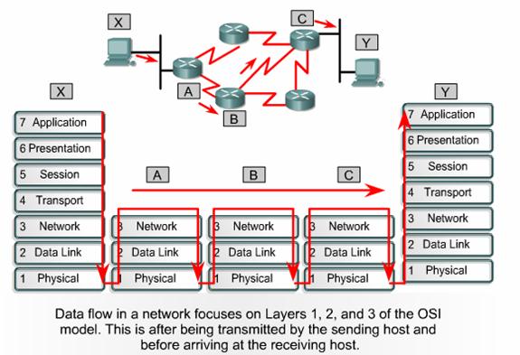
Data
flow in the context of collision and broadcast domains focuses on how data
frames propagate through a network. It refers to the movement of data through
Layers 1, 2 and 3 devices and how data must be encapsulated to effectively make
that journey. Remember that data is encapsulated at the network layer with an
IP source and destination address, and at the data-link layer with a MAC source
and destination address. ![]()
A good rule to follow is that a Layer 1 device always forwards the frame, while a Layer 2 device wants to forward the frame. In other words, a Layer 2 device will forward the frame unless something prevents it from doing so. A Layer 3 device will not forward the frame unless it has to. Using this rule will help identify how data flows through a network.
Layer 1 devices do no filtering, so everything that is received is passed on to the next segment. The frame is simply regenerated and retimed and thus returned to its original transmission quality. Any segments connected by Layer 1 devices are part of the same domain, both collision and broadcast.
Layer 2 devices filter data frames based on the destination MAC address. A frame is forwarded if it is going to an unknown destination outside the collision domain. The frame will also be forwarded if it is a broadcast, multicast, or a unicast going outside of the local collision domain. The only time that a frame is not forwarded is when the Layer 2 device finds that the sending host and the receiving host are in the same collision domain. A Layer 2 device, such as a bridge, creates multiple collision domains but maintains only one broadcast domain.
Layer 3 devices filter data packets based on IP destination address. The only way that a packet will be forwarded is if its destination IP address is outside of the broadcast domain and the router has an identified location to send the packet. A Layer 3 device creates multiple collision and broadcast domains.
Data flow through a routed IP based network, involves data moving across traffic management devices at Layers 1, 2, and 3 of the OSI model. Layer 1 is used for transmission across the physical media, Layer 2 for collision domain management, and Layer 3 for broadcast domain management.
|
|
|
|
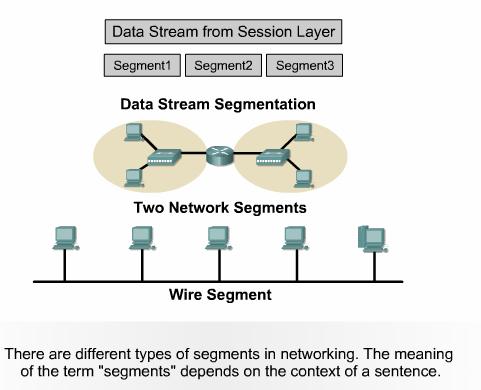
As with many terms and acronyms, segment has multiple meanings. The dictionary definition of the term is as follows:
In the context of data communication, the following definitions are used:
To
properly define the term segment, the context of the usage must be presented
with the word. If segment is used in the context of TCP, it would be defined as
a separate piece of the data. If segment is being used in the context of
physical networking media in a routed network, it would be seen as one of the
parts or sections of the total network. ![]()
The Interactive Media Activity will help students identify three types of segments.
|
|
|
Summary |
Ethernet is a shared media, baseband technology, which means only one node can transmit data at a time. Increasing the number of nodes on a single segment increases demand on the available bandwidth. This in turn increases the probability of collisions. A solution to the problem is to break a large network segment into parts and separate it into isolated collision domains. Bridges and switches are used to segment the network into multiple collision domains.
A bridge builds a bridge table from the source addresses of packets it processes. An address is associated with the port the frame came in on. Eventually the bridge table contains enough address information to allow the bridge to forward a frame out a particular port based on the destination address. This is how the bridge controls traffic between two collision domains.
Switches
learn in much the same way as bridges but provide a virtual connection directly
between the source and destination nodes, rather than the source collision
domain and destination collision domain. Each port creates its own collision
domain. A switch dynamically builds and maintains a Content-Addressable Memory
(CAM) table, holding all of the necessary MAC information for each port.
Two devices connected through switch ports become the only two nodes in a small collision domain. These small physical segments are called microsegments. Microsegments connected using twisted pair cabling are capable of full-duplex communications. In full duplex mode, when separate wires are used for transmitting and receiving between two hosts, there is no contention for the media. Thus, a collision domain no longer exists.
There is a propagation delay for the signals traveling along transmission medium. Additionally, as signals are processed by network devices further delay, or latency, is introduced.
How a frame is switched affects latency and reliability. A switch can start to transfer the frame as soon as the destination MAC address is received. Switching at this point is called cut-through switching and results in the lowest latency through the switch. However, cut-through switching provides no error checking. At the other extreme, the switch can receive the entire frame before sending it out the destination port. This is called store-and-forward switching. Fragment-free switching reads and checks the first sixty-four bytes of the frame before forwarding it to the destination port.
Switched networks are often designed with redundant paths to provide for reliability and fault tolerance. Switches use the Spanning-Tree Protocol (STP) to identify and shut down redundant paths through the network. The result is a logical hierarchical path through the network with no loops.
Using Layer 2 devices to break up a LAN into multiple collision domains increases available bandwidth for every host. But Layer 2 devices forward broadcasts, such as ARP requests. A Layer 3 device is required to control broadcasts and define broadcast domains.
Data flow through a routed IP network, involves data moving across traffic management devices at Layers 1, 2, and 3 of the OSI model. Layer 1 is used for transmission across the physical media, Layer 2 for collision domain management, and Layer 3 for broadcast domain management.
|
|
|
Overview |
The Internet was developed to provide a communication network that could function in wartime. Although the Internet has evolved from the original plan, it is still based on the TCP/IP protocol suite. The design of TCP/IP is ideal for the decentralized and robust Internet. Many common protocols were designed based on the four-layer TCP/IP model.
It is useful to know both the TCP/IP and OSI network models. Each model uses its own structure to explain how a network works. However, there is much overlap between the two models. A system administrator should be familiar with both models to understand how a network functions.
Any device on the Internet that wants to communicate with other Internet devices must have a unique identifier. The identifier is known as the IP address because routers use a Layer 3 protocol called the IP protocol to find the best route to that device. The current version of IP is IPv4. This was designed before there was a large demand for addresses. Explosive growth of the Internet has threatened to deplete the supply of IP addresses. Subnets, Network Address Translation (NAT), and private addresses are used to extend the supply of IP addresses. IPv6 improves on IPv4 and provides a much larger address space. Administrators can use IPv6 to integrate or eliminate the methods used to work with IPv4.
In addition to the physical MAC address, each computer needs a unique IP address to be part of the Internet. This is also called the logical address. There are several ways to assign an IP address to a device. Some devices always have a static address. Others have a temporary address assigned to them each time they connect to the network. When a dynamically assigned IP address is needed, a device can obtain it several ways.
For efficient routing to occur between devices, issues such as duplicate IP addresses must be resolved.
This
module covers some of the objectives for the CCNA 640-801, INTRO 640-821, and
ICND 640-811 exams. ![]()
![]()
![]()
Students
who complete this module should be able to perform the following tasks: ![]()
Use ARP to obtain the MAC address to send a packet to another device
Understand the issues related to addressing between networks.
|
