A low-cost image processing engine capable of visually tracking eight objects of eight different user-defined colors, at 27 frames per second.
The ability for humans to perceive and process their environment through their senses has always fascinated me. Every time I am walking on a crowded sidewalk, dodging all of the obstacles around me, keeping pace with the flow of people, planning my next step, it reminds me how advanced our sensory input systems really are.
Artificial vision systems are complex. These systems typically require a considerable amount of computing power to acquire and process their environments in real-time. The end goal of most vision systems is to determine specific information about their environment: How many different objects exist? Are objects moving? What are the colors of the objects? How far away are the objects? The answers to these questions are needed to allow for the appropriate post-processing of the environment, as required by a particular application.
Several systems exist that can perform vision processing at various capability levels. At the hobbyist level, the CMUcam [1] provides a small, low-cost system capable of tracking a single colored object at 16.7 frames per second. This system utilizes a Ubicom SX28 microcontroller running at 75 MHz to acquire and process images through software. A step up from CMUcam is the Cognachrome [2] system, which is capable of tracking multiple objects of various colors at 60 frames per second. This system costs several thousand dollars, and performs much of its image processing in hardware.
Enter AVRcam...
AVRcam is a stand-alone image-processing engine based on the Atmel ATmega8 microcontroller. This engine is capable of tracking eight objects of eight different user-defined colors, at 27 frames per second. The system provides a user-interface, through a well-defined protocol, over a standard serial port (UART). The user-interface provides the following image information to the user in real-time:
number of currently tracked objects
color of each tracked object
center point of each tracked object
bounding box of each tracked object
The system also allows the user to take snapshots of its current field of view, allowing the user to better understand how the AVRcam is sensing its environment. The AVRcam is shown in Photo 1.
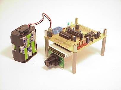
Photo 1: The AVRcam Version 1.0
A PC-based application (AVRcamVIEW) was also developed to provide a platform for evaluating, testing, and configuring the AVRcam. This application interfaces to the AVRcam through the standard RS232 port on any PC. This application allows the user to take snapshots with the AVRcam, and view them or save them for later use. Once a snapshot is taken, the user can quickly set up the color map to be used by the AVRcam, by simply clicking on the colors of interest. AVRcamVIEW will automatically build and download a color map to the AVRcam for to be used during object tracking. Finally, AVRcamVIEW can display the real-time tracking results to the user. An example screenshot is shown in Photo 2.
The AVRcam was developed for the purpose of enabling mobile robots to perceive their environment in a small form-factor, low-power, high-capability package. A typical embedded configuration would have the AVRcam connected to another microcontroller, which accesses the AVRcam through its serial user-interface. This type of system is especially useful when the environment in which a robot operates can be defined by the colors around it. An example of this is the RoboCup [3] robot soccer competition held each year. The AVRcam system can be easily interfaced to a robot to provide high-level, real-time information about the robot's environment.
The goal of the AVRcam vision engine was to provide a small, low-power system capable of tracking multiple colorful objects in real-time. Minimally, such a system would need to consist of an image sensor that would be responsible for converting images into a useable format for processing, a computing entity, and a user-interface.
The Omnivision OV6620 CMOS color image sensor was chosen as the image sensor for the AVRcam. This low-cost sensor provides a simple digital interface to access the camera's captured images. The OV6620 is capable of providing either CIF (352 x 288) or QCIF (176 x 144) resolution color images in Bayer format at up to 30 frames per second.
The Atmel ATmega8 provides an almost ideal combination of speed, peripherals, and memory for interfacing to the OV6620 image sensor. This 24-pin device can execute at speeds up to 16 MHz through an external crystal, providing up to 16 MIPS of processing power to acquire and process images. It contains 8K of flash for code, 1K of RAM for data storage, and 512 bytes of EEPROM for non-volatile data storage. It provides ample general purpose i/o, as well as an excellent combination of interrupts, counters, and serial ports to deal with the demanding requirements of the OV6620. Figure 2 shows the hardware block diagram of the AVRcam in its entirety.
There are several important hardware elements in the AVRcam block diagram that require explanation. For starters, the pixel busses provided by the OV6620 are not used in their entirety. Only the upper nibble (4-bits) of each bus is sent to the ATmega8. The lower nibble of each port is not connected. This allows a smaller dynamic range of color (only 16 possible values for each sampled pixel, or 4096 colors when 4-bits of each RGB is considered) for each channel, but provides a significant advantage in terms of required processing (it reduces the data by a factor of 2). Early testing showed that 4-bits per pixel was plenty of resolution to meet the color differentiation requirements for tracking. This will be further discussed in the software section.
The second critical element is that the 16 MHz crystal that clocks the ATmega8 is also connected to the OV6620's external clock input line. This not only eliminates the need to have a crystal connected to the camera, but it allows both the ATmega8 and the OV6620 to run synchronous to each other. This means that with careful programming, the data on the pixel busses can be sampled without having to check the state of PCLK every time. This provides the key to processing such a massive quantity of data in real-time. This will also be discussed in the software section.
The ATmega8 also provides both the Two-Wire Interface (I2C compatible) required to configure the OV6620, as well as a hardware UART that provides the user-interface to the outside world.
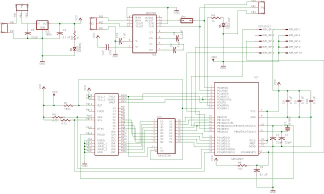
A printed circuit board was created for this project, as shown in Figure 1. The complete schematic of the AVRcam can be found in Appendix A. The AVRcam requires a 5 Volt supply, and draws approximately 53 mA when running at full speed.
The choice of the ATmega8 running at 16 MHz provided a considerable amount of computing power to acquire and process the data provided by the OV6620. The software developed for the AVRcam is partitioned into seven distinct modules. These modules are shown in block-diagram format in Figure 3. The software was written primarily in C (using the GNU AVR-GCC C compiler), but several of the time-critical routines were written in Assembly. This allowed for precise control of the number of instruction clock cycles needed to execute the pixel acquisition routines. The AVRcam uses 4062 bytes of the 8K flash memory, 692 bytes of the 1K RAM, and 48 bytes of the 512 byte EEPROM.
A simple Executive is responsible for dispatching events throughout the system. The Executive contains both an event FIFO as well as a fast-event bitmask. The fast-event bitmask is used to notify waiting modules when high-priority events occur in the system. The event FIFO is used to store lower-priority events as they are created in the system.
Image Dumping (Snapshot) Algorithm
As shown in the hardware block diagram, pixel data is sampled through the lower nibbles of PORTC and PORTB of the ATmega8. With the VSYNC line hooked up to External Interrupt 0, the ATmega8 knows exactly when a frame of data has started. Once the data has started, the rising edge of HREF (which is hooked up to External Interrupt1) will indicate when each line begins. Since the PCLK is connected to Timer1 (configured as a 16-bit counter with interrupt on overflow), it is possible to pre-load the counter to overflow after 176 pixels have been sampled, thus indicating that the line has been acquired. At no time is it necessary to actually check the state of the PCLK line, since we synchronize with it at the beginning of each line through the HREF signal.
When dumping a line of data in Snapshot mode, there are 8 instruction clock cycles between each sampled pixel. This leaves enough time to read each pixel and store it off to a buffer for processing when the line is done. Only one line of pixels is acquired and sent per frame. Thus, it takes around 4 seconds to acquire and output a complete frame of data. This flow is shown in Flowchart 1.
Image Tracking Algorithm
When the system is in tracking mode, only half the pixels in each line are sampled, for a total of 88 pixels per line. The time between "pixel blocks" (defined as an R-G-B triplet) is eight clock cycles. Skipping every other pixel block allows for sixteen clock cycles to sample the pixel block, map the R-G-B triplet to an actual color (based on an algorithm developed at Carnegie Mellon University [4]), and run-length encode the line of data. This process is shown in Flowchart 2.
Waiting to acquire a dump line: Waiting to acquire a tracking line:
Close
out last run-length
 Flowchart 1: Acquiring a Dump Line
NO Color == LastColor?
![]()
![]()

TCNT Overflow Interrupt Service Routine:
YES
![]()
![]()
![]()
Flowchart 3: Pixel Count Overflow ISR Flowchart 2: Acquiring a Tracking Line
Once a line of tracking data has been acquired, the run-length-encoded line of data needs to be processed. It is compared to the previous line of run-length-encoded data to check for connectedness. If connectedness is found, the TrackedObjectTable is updated to reflect the new data. This FindConnectedness routine needs to complete in less than 100 uS, the approximate time before the next line of pixel data begins,
Once a complete frame of data is acquired, the contents of the TrackedObjectTable are written to the transmit FIFO of the User-Interface Manager. Then, the system goes to sleep, waiting for the next frame to begin. The data in the User-Interface Manager transmit FIFO is sent out one byte at a time after each line has been acquired. Assuming it takes ~86 uS to transmit a byte of data at 115.2 Kbps, this one-byte-at-a-time transmission will be simultaneous with the acquisition of each line of pixel data in the next frame.
Conclusion
The AVRcam is a simple, low-cost vision engine capable of tracking up to eight colorful objects at 27 frames per second. This system provides a simple user-interface over a serial port, enabling both low-end microcontrollers and PCs to communicate with the system. The AVRcam is ideally suited to enable a small mobile robot with the ability to perceive the colors in its environment in real-time. While this system is still no match for the human vision system, the AVRcam finally makes low-cost, real-time image acquisition and processing a reality.
Appendix A
AVRcam v1.0 Schematic
Appendix B
References
[1] https://www-2.cs.cmu.edu/~cmucam/
|
