How to create and import images for further design work in SketchUp
In order to be able to capture images for use in SketchUp we will first
download and learn how to use a small programme called "Faststone Capture".
This programme is very useful for capturing images - not only for use in
SketchUp, but also in many other software applications. Go to this homepage: https://www.faststone.org/FSCaptureDetail.htm
and download the programme. Once downloaded you install it, and, when
activating you will get a small floating toolbar looking like this: ![]() .
.
To begin with we will use only very few of the many features available
in the programme. Let us make a small exercise to see how it works. The programme
works in the way that you select what you want to copy by dragging a frame
across you window in order to define what you want to copy. The button we will
use most frequently is this:![]() .
.
Try clicking on the button and you get a red "cross hair". Click on a start point and drag the frame across the screen and the click on a stop point on your screen. Apparently nothing happens !!!
However, depending on the settings controlled here:
you will get a list of options like these:
We will use these options for different purposes. Sometimes it is convenient to use the "To clipboard" option. Let us try it now.
Open a site on the internet from where you would like to "steal" an
image. Also open a programme, for example "Word". Now activate Faststone - chose
the "to clipboard" option as referred to above. Next you click on this button ![]() .
.
Go to the internet page and drag a frame across the picture you want to copy - clicking where you want begin and where you want to stop.
Go back to Word. Right-click on your mouse and choose "paste". Your picture now appears in word - and you can resize and move it as you like.
We shall now see how we can use the programme for importing images into
SketchUp. The method described above cannot be used in this case. First
we will have to change settings in such a way that we will now save the image
in a file. Click here  and check (select) "To file".
Before we continue, we will need yet some more folders in the folder system which we created at the beginning of the drawing technique course. Go to your own personal drive (the G-drive) and open the folder "Drawing technique". Create new subfolders named "Scanned images" and "SketchUp drawings" .
![]()
![]()
![]() These are the new subfolders you are supposed
to create
These are the new subfolders you are supposed
to create
Next step will be to open the file from where you "snap a picture". You can snap a picture from any file format. Below I am showing how you can snap a picture from a pdf-file (that I have scanned from my PC.
Start by opening the file from where you want to snap the image to be imported into SketchUp.
Next you click here and start and end as indicated below
Once you have clicked on "Slut her" (End here) the programme will ask you where you want to save the file. Go to the folder "scanned images" that you just finished to create. Save the file with an appropriate name, for example "l-shaped house" Make sure to save the file as type *.png (save as type).
We are now ready ti import the file into SketchUp
Open SketchUp.
Click on "File"->"Import"
Find the folder "Scanned images" and find the file "l-shaped house".In case the file does not appear on the list, you may need to click on "Files of type" below and find "(*.png)".
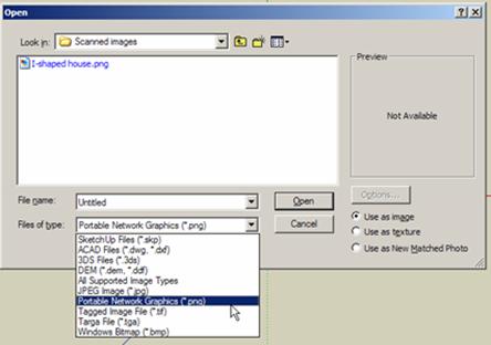
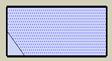
Click on "open". As the insertion point we will use "Origo". Click in Origo, and move the cursor toward the right until the image has a reasonable size. Click somewhere on the image and the import is finished. Now we only need to check, and possibly adjust, the size of the image.

 Use the "Tape
measure"
Use the "Tape
measure" ![]() to
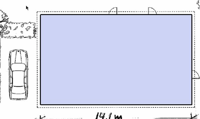
check the distance as indicated here. . The measurement also appears in the
VCB. Write the correct measurement in VCB, i.e. 14100 mm. Click on "ENTER" and
this dialogue box pops up:
to
check the distance as indicated here. . The measurement also appears in the
VCB. Write the correct measurement in VCB, i.e. 14100 mm. Click on "ENTER" and
this dialogue box pops up:
Click on "Yes" and the drawing obtains the right size - try to measure again.
Before you continue, you must save the file. Click on "File"->"Save as" and find the folder "Drawing Technique" (in your VIA-files folder). Save the model (drawing) as"l-shaped house".
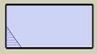
The image is still a picture and not a SketchUp "face". Try to draw a line across one of the corners as shown below:
The line appears thick and when you click on either side of the line you do not see any difference as you would normally do in a SketchUp rectangle. Draw a small rectangle next to the map in order to test it out. It looks like this when you click on one side or the other:
It is possible to make "our" pla 14214m1216o n "behave" in the same way - this is sometimes desirable. In order to do so, place the cursor on top of the map and right-click. Choose the option "explode". Now you will see that the line turns thin and if you try to click on either side of it you will notice that the map behaves like a normal SketchUp rectangle, i.e. it is now a "face".
However, we do not want to use this option in this exercise. Therefore
click on the"UNDO" button ![]() in order to cancel the "Explode" command.
in order to cancel the "Explode" command.
Now, click on the rectangle tool ![]() (shortcut "R"). Pull a rectangle across your
plan starting in one of the exterior wall corners and ending in the diametrically
opposite corner.
(shortcut "R"). Pull a rectangle across your
plan starting in one of the exterior wall corners and ending in the diametrically
opposite corner.
The plan now appears like this:
In the usual SketchUp manner we have now created a face and as a result
we can no longer see the plan below. In order to be able to continue we must be
able to see the plan. We will therefore active our "X-ray" vision. Click on ![]() found
on the tool bar "Face style" (in case it is not active you need to activate it
here: "View"->"Toolbars"). On the next page you can see the result of this
action.
found
on the tool bar "Face style" (in case it is not active you need to activate it
here: "View"->"Toolbars"). On the next page you can see the result of this
action.
 It is now possible to see the
plan again and the face we created still exists (you may try to click on the centre
part of the plan and the face appears as a rasterised surface (small
dots).
It is now possible to see the
plan again and the face we created still exists (you may try to click on the centre
part of the plan and the face appears as a rasterised surface (small
dots).
Choose "Offset " ![]() (shortcut
"O")and click somewhere in the centre of the plan. Try to move the cursor
toward one of the corners. You will notice that a new rectangle is being
proposed with sides parallel to the existing. Moving in one direction results
in the drawing of a rectangle with sides congruent to the existing rectangle,
and moving in the other direction results in the drawing of a rectangle with
sides perpendicular to the existing. This function is known as "off set" When the rectangle appears with the
shape you want, you simply write the desired distance between the new and the
old rectangle in the VCB. Let us define the external wall to be 348 mm thick.
Simply write 348 in the VCB and press "ENTER". Your drawing is now supposed to look as the
illustration shown on the next page.
(shortcut
"O")and click somewhere in the centre of the plan. Try to move the cursor
toward one of the corners. You will notice that a new rectangle is being
proposed with sides parallel to the existing. Moving in one direction results
in the drawing of a rectangle with sides congruent to the existing rectangle,
and moving in the other direction results in the drawing of a rectangle with
sides perpendicular to the existing. This function is known as "off set" When the rectangle appears with the
shape you want, you simply write the desired distance between the new and the
old rectangle in the VCB. Let us define the external wall to be 348 mm thick.
Simply write 348 in the VCB and press "ENTER". Your drawing is now supposed to look as the
illustration shown on the next page.
![]()
Notice how the area between the two lines (the wall) is now rasterised.
The external wall has now been drawn. (You may try to switch the "X-ray"
vision ![]() on and off again - in this way you can better see the wall).
on and off again - in this way you can better see the wall).
In principle we are now ready to start drawing the internal walls, but before we do so, we need to look at an important function which makes it a lot easier to work with models (drawings) in SketchUp. The function we will look at first is called "Group"
To begin with we will make a small experiment in order to illustrate how this function works and some of the advantages attached to the use of this function. Draw a small box in SketchUp as shown in the example below:
Now draw another box on top of it as shown here:
In principle we have drawn to separate boxes (notice the separating line along the edge).
We will now attempt to move the topmost mox - without touching the lowermost box. First we select the topmost box by dragging a window across it from left to right:
It may be easier to do so if you click on "Front view" before you select
the box. In case you do not succeed in
selecting all the edges of the box (as shown here) you may select the remaining
edge(s) by holding down the "SHIFT" button clicking at the line at the same
time using the "Select" tool ![]() at the
same time (shortcut: "Space bar" ).
at the
same time (shortcut: "Space bar" ).
Now you activate the "Move" tool ![]() and
click on one of the corners of the selected box. Click once and try to move the
box upwards (vertically along blue axis).The result of this action can be seen
in the next image.
and
click on one of the corners of the selected box. Click once and try to move the
box upwards (vertically along blue axis).The result of this action can be seen
in the next image.
In doesn't look too good!! We can do better than that - otherwise we will definitely get problems in separating elements when we start designing a proper house.
Try now to right-click on the selected box. On the pop-up menu you choose "Make Group" and the image will appear as indicated below.
 Notice how the blue line
marking the box now appears as a double line. When you click somewhere outside
the model, the blue marking disappears, but as soon as you click on the box
again, it reappears.
Notice how the blue line
marking the box now appears as a double line. When you click somewhere outside
the model, the blue marking disappears, but as soon as you click on the box
again, it reappears.
Try to activate "Move" ![]() again.
Click on the box and hold down the mouse button while you move the box somewhere else.
again.
Click on the box and hold down the mouse button while you move the box somewhere else.
It is now possible to move the box without affecting the other box. With the small box moved away from the big one, try now to make also the big box a group and notice how easy it is to move the boxes around and even connecting them again without "sticking" to each other.
This small exercise has hopefully helped you in understanding how elements "stick" together in SketchUp unless you are careful. Based on this experience we can now put words on a very basic drawing rule in SketchUp:
All elements in your model (drawing) must constitute a group or a component (more about components later)
Based on the experience we have just achieved, we will now start by turning our external wall into a group. Doing so we may prevent the wall from sticking to other elements that we will draw later (like the internal walls).
Double-click somewhere on your external wall (between the wall lines) until all lines turn blue. Right-click and choose the option "Make group".
Before we start drawing the internal walls we will have a look at the way we organize and manage the groups we are making in the model. Click on "Window"->"Outliner" and the submenu shown on the next page pops up. You can move this box around your screen area by clicking the blue top bar and pulling the box while holding down the mouse button. . Place the box next to your plan on the right hand side of the screen as indicated below
So far we have to sets of information in "Outliner". On top the name of the model (file name) appears. Below, it says "Group". Click on "Group" and you will notice how the word Group is now being highlighted (blue colour) and the group you have just finished to make in the drawing is also being highlighted. Right-click on "Group" and choose "Rename" in order to give the group an appropriate name. Write "External wall"
From now on, every time we make a new group we will immediately give it an appropriate name. In this way we will always be able to identify and find the group again in Outliner whenever we need to do so.
Subsequently, I will try to explain why it is such a good idea to use
Outliner for organising and managing your groups (and later on also
components). However, before we come to that, we need to have a look at what
actually happens when we make a group. Try now to switch your plan into "Iso"
view ![]() .
.
We will now try to "raise" the
walls using the Push/Pull ![]() .
You will notice at once that this is not possible.
.
You will notice at once that this is not possible.
Groups are protected in such a way that they cannot accidentally be changed. We may, of course, unlock the groups again in order to edit them as we like. Unlocking can be done in different ways; but the best way is to use "Outliner". Now, double click on "External walls" in "Outliner"
Notice how the "external wall" group fades out and is being surrounded by a dotted lined box. This signals, that you may now edit the group. Try again to use the "Push/Pull" tool. This time it works. Once you have finished editing, you simply click somewhere outside the group and I closes again and you can no longer edit it.
Before we continue, go back to "Top"view ![]() .
.
We will now start drawing the internal walls. For this purpose we will
make use of the "Tape measure" ![]() tool.
tool.
Apart from being useful for measuring and scaling to size (as we have already seen) this tool is also useful for making "Guides", which - as we shall se - are very handy. On the following page you can see how to go about the construction of "guides"
This is what you do:

 Click
on
Click
on ![]() .
Next, you click on one of the inside lines of the exterior wall - somewhere on
the middle. Move the cursor toward the centre of the building. You will notice
the appearance of a dotted line perpendicular to the direction of cursor
movement.
.
Next, you click on one of the inside lines of the exterior wall - somewhere on
the middle. Move the cursor toward the centre of the building. You will notice
the appearance of a dotted line perpendicular to the direction of cursor
movement.
![]()
![]()
 You may start here and stop
here. It is a good idea to zoom in order to be able to see exactly where you
want to place your guide - in this case along the sides of an internal wall. To continue,
you click on the guide you have just constructed and move the cursor toward the
right, but this time you write the desired wall thickness - in this case 120 mm
- in the VCB after which you press
"ENTER". The guide appears. Now, using
these principles, you construct guides on top of all the internal walls. Once
you have finished the guides you can easily draw lines for the internal walls
on top of the guides. Once you have finished drawing the internal walls, you
may delete the guides again. Click on "Edit"-> "Delete guides".
You may start here and stop
here. It is a good idea to zoom in order to be able to see exactly where you
want to place your guide - in this case along the sides of an internal wall. To continue,
you click on the guide you have just constructed and move the cursor toward the
right, but this time you write the desired wall thickness - in this case 120 mm
- in the VCB after which you press
"ENTER". The guide appears. Now, using
these principles, you construct guides on top of all the internal walls. Once
you have finished the guides you can easily draw lines for the internal walls
on top of the guides. Once you have finished drawing the internal walls, you
may delete the guides again. Click on "Edit"-> "Delete guides".
On the following page you can see how all the internal wall have now
been drawn and selected using the "Select" ![]() tool - you may need to use the "SHIFT" key in
combination with the "select" tool in order to be able to select all walls at
one time (notice that guidelines have not been deleted on this illustration).
tool - you may need to use the "SHIFT" key in
combination with the "select" tool in order to be able to select all walls at
one time (notice that guidelines have not been deleted on this illustration).
Having selected all the internal walls you right-click and make a new group and rename it "internal walls" (in Outliner).
We are now ready to "erect" the walls. Change view to "Iso" ![]() . Open the "Outliner"
. Open the "Outliner"
![]() Double click on
"External wall" in order to open the group for editing, and
Double click on
"External wall" in order to open the group for editing, and ![]() push the wall up by 2500 mm.
push the wall up by 2500 mm.
p
I order to get a better view it may be a good idea to switch off the
"X-ray " ![]() face style.
face style.
See next illustration.
 The internal wall group has
now been opened for editing. Push up to walls the same level as the external
wall by using "inference" function.
The internal wall group has
now been opened for editing. Push up to walls the same level as the external
wall by using "inference" function.
When you have finished erecting the external and internal walls your model looks as shown on the next illustration.
 The groups are closed again.
We will now make openings for windows and doors. Start by switching on the "X-ray" face style.
You are now able to see the position of all door and window openings.
Before we start drawing openings, we will draw guides on the facades and the gables in order to position the openings correctly.
Fist we will indicate a top and a bottom line for windows (as they are generally placed). Normally the top level of doors and windows is the same - somewhere between 2100mm and 2200 mm. We decide to make it 2150mm
Use "front" view in order to make the building face you. Activate the tape measure tool.
Snap to the base line of the wall and start moving upwards - ensuring that you move in the direction of the blue axis (blue dotted line indicates this). Write 2150mm in the VCB and press "ENTER". Using the same method, you make a line indicating the bottom level of the windows which is normally around 900 mm above the baseline. Shifting between "Front", "Right", "Back" and "Left" views you draw similar lines on all the faces of the house.
 When you have finished making
horizontal guides your model looks like this:
When you have finished making
horizontal guides your model looks like this:
You now proceed with the vertical guides for windows and doors. This time you start at the corner of one of the buildings and move the cursor in the red (or green) direction. Place guides where an opening starts and where it ends - using the plan to guide you.
 Make sure to move in the right
direction. You may lock the direction by pressing the
Make sure to move in the right
direction. You may lock the direction by pressing the
arrow keys

Horizontal arrows lock red/green direction. Vertical arrows lock blue direction
Once you have finished all horizontal lines, it may be a good idea to switch off X-ray, in order to find out whether all the guides are placed in the right plane. The guides must be visible and placed on the wall surfaces. See next page.
Check your plan again. Sometimes the windows in bathrooms and WCs are smaller than the windows in other rooms, i.e. the level of the sill (the bottom) is higher - for example 1500mm (in stead of 900 mm).
Make sure your "Outliner" is switched on. "Open" external walls in order to make the editable.
Now you can start drawing the windows. Use the ![]() tool
and draw rectangles across all openings.
tool
and draw rectangles across all openings.
 Using the
 ![]() tool you start clicking here and
tool you start clicking here and
end clicking here

Draw rectangles on all openings - in case you have doubts concerning the placement of an opening, you can always switch on the X-ray enabling you to get a better view.
 Activate the Push/pull tool
 ![]() and create a window opening by pushing the
rectangle towards the inside until you get an opening.
and create a window opening by pushing the
rectangle towards the inside until you get an opening.
Repeat the process for all openings in external walls.
When you have finished external wall openings - you may continue with internal walls (door openings - height 2100 mm)
Once you have drawn all opening your plan looks like this (hopefully):
This is how you remove the guides: Click as shown below:
We will now try to find some windows and doors and adapt them to the openings we have created.
However, before we do so, we will have a look at another SketchUp facility called "Components". In order to get a deeper understanding of this facility I recommend you to study "SketchUp for Dummies" pages 124-143. As for now we will just start using the facility
Click on "Window"-> "Components" and this palette appears.
![]() The
contents do not look very impressive, but try to click on this small arrow
The
contents do not look very impressive, but try to click on this small arrow
On the next page you can see what options are now available

 Try
to open the folder "Architecture". In this folder
you can find some windows and doors, but maybe not the types you are looking
for. Other libraries containing much
more components exist on the Internet. We can download components directly from
these libraries into SketchUp. Let us
try to access the net to see what we can find.
Try
to open the folder "Architecture". In this folder
you can find some windows and doors, but maybe not the types you are looking
for. Other libraries containing much
more components exist on the Internet. We can download components directly from
these libraries into SketchUp. Let us
try to access the net to see what we can find.
Click on this button and you will leave the programme and "fly" directly to the Internet. The starting page is shown below.
 Like in normal
"Google" you write what you are looking for here - for example "Windows"
Like in normal
"Google" you write what you are looking for here - for example "Windows"
Once you have entered what you want to look for, you simply click on "ENTER" and you will be given a number of options to choose from. Study the images carefully and once you see something to your liking you can click on it to take a closer look. In case you find it suitable, you can click on "Download" and the component will be loaded directly into your model where you will be able to manipulate with it like any other component found in SketchUp libraries. NOTICE that not all models (components) found on the Internet have the same high quality - some are made by very skilled users while others are made by not so skilled amateurs.
Some times it is easier to find what you are looking for in the default libraries made by SketchUp. You may download additional libraries here: https://sketchup.google.com/bonuspacks.html
 Download the libraries and
place them in this library on your hard drive:
Download the libraries and
place them in this library on your hard drive:
C:\Program files\Google\Goggle SketchUp6\ Components
 Save your drawing. Close down
your programme and re-open it. The new component libraries will now be
available. You can find the windows you're a looking for in the library "architecture"
-look in the sub-folder "windows"
Save your drawing. Close down
your programme and re-open it. The new component libraries will now be
available. You can find the windows you're a looking for in the library "architecture"
-look in the sub-folder "windows"
 Click to open and
you will find a variety of windows
Click to open and
you will find a variety of windows
Choose the window type you want, and "drag" it into the right position in your drawing. It may be a good idea to zoom in first.

 Notice that the window has a
predefined insertion point (in case you want to know more about insertion
points; I recommend that you read page 133 in "SketchUp for Dummies"
Notice that the window has a
predefined insertion point (in case you want to know more about insertion
points; I recommend that you read page 133 in "SketchUp for Dummies"
It is quite obvious that the window shown above does not fit into the window opening in the wall. - This is how you adjust that:
 Click on the window in order to selct it. (all in blue). Next
you click on the Scale Tool
Click on the window in order to selct it. (all in blue). Next
you click on the Scale Tool ![]() and the window appears as shown here:
and the window appears as shown here:
Turn the model a little in order to be able to side the sides of the window - see below
 Notice the green buttons or
handles placed on all corners and on the middle of every side. There are always 3 of them
placed together. Try to "catch" the middle button on the middle of the window side. It
changes colour to red. You must now pull the button towards the side of the
window opening. When you get the message "on edge in component", you click and
the window has been adjusted
Notice the green buttons or
handles placed on all corners and on the middle of every side. There are always 3 of them
placed together. Try to "catch" the middle button on the middle of the window side. It
changes colour to red. You must now pull the button towards the side of the
window opening. When you get the message "on edge in component", you click and
the window has been adjusted
Repeat this procedure for adjustment of window size in the opposite direction.
The window now fits into the opening. Repeat this procedure for all the windows.
Find doors and proceed in the same manner.
Once you have inserted all windows and doors it is time to have a look at the "Outliner" again:
All window and door components are now listed in the "Outliner. We would like to make the window and door components appear in the same group as the External walls in order to be able to switch them on and off together with the walls. In order to do so hold down the SHIFT key simultaneously to clicking on every window and door component. Once they are all selected you drag them all into the "External wall" group.


 Once you click on the
 ![]() next to "External walls" you collapse the
group, and doors and windows are now embedded in the group "External walls"
next to "External walls" you collapse the
group, and doors and windows are now embedded in the group "External walls"
Try to "hide " External walls" (right-click -and choose "Hide"). The walls including doors and windows are now hidden.
External walls "switched on"
External walls "switched off"
Now it is easy to work "undisturbed" with the insertion of doors in the," Internal walls" - proceed in the same way as you did with windows and external doors.
The internal doors are now inserted. Move them to the "internal walls" group in "Outliner" like you did with windows and doors in the "External walls"
Once you have finished all doors and windows, you switch on the groups again in order to see the finished result.
Next step will be to put a roof on the building. There are many ways of doing so. I will show you a method that can be applied at roof with different roof pitches.
 Start by drawing a rectangle
spanning across the entire building using the rectangel tool
Start by drawing a rectangle
spanning across the entire building using the rectangel tool ![]()
Use the Offset tool ![]() . Click on the "new" rectangle and move the cursor outside the building. Without
clicking you now write "300 mm" in the VCB (lower right corner). Press "ENTER"
and you have the beginning of the roof with an overhang of 300 mm.
. Click on the "new" rectangle and move the cursor outside the building. Without
clicking you now write "300 mm" in the VCB (lower right corner). Press "ENTER"
and you have the beginning of the roof with an overhang of 300 mm.
Double click on the rectangle until all lines and faces in the rectangle turn blue (selected). Right-click and create a group. In "Outliner" rename the group "Roof" and double click on the group in order to make it editable
We would also like to add some thickness to the overhang. Activate push/pull
![]() .
Click on the outermost part of the rectangle ad push it up by 120mm ((write
"120" in the VCB and press ENTER). See the result of these actions below.
.
Click on the outermost part of the rectangle ad push it up by 120mm ((write
"120" in the VCB and press ENTER). See the result of these actions below.
 Click on "right view"
 ![]() in
order to see the gable of the house. Acivate "Protractor" and let the protractor rest on the gable, placing the centre
as shown. Click and move the cursor towards the right
(along green axis). Click again somewhere along the axis. Rotate the protractor wheel upwards.
in
order to see the gable of the house. Acivate "Protractor" and let the protractor rest on the gable, placing the centre
as shown. Click and move the cursor towards the right
(along green axis). Click again somewhere along the axis. Rotate the protractor wheel upwards.
Write "27" in the VCB. You have now established a guide with a 27 degree inclination.
Do the same thing on the opposite side of the building and you get this result:
 Draw proper lines using the
pencil tool
Draw proper lines using the
pencil tool ![]() on top of the guides
on top of the guides
On the next page you can see the result
Rotate the model by holding down the mouse wheel and moving the mouse at the same time. Try to position your model as shown below.
 Activate push/pull
 ![]() again and pull the gable across the building
stopping at the other end until the roof has been shaped.
again and pull the gable across the building
stopping at the other end until the roof has been shaped.
Try closing the group by clicking somewhere outside the model. Go to "Outliner" and try to "hide" the roof. "
We would like to remodel the gable slightly in order to make it look more realistic. Before you continue make sure the roof group is in "edit mode" (double click on "Roof" in "Outliner").
Click on "Right" view ![]() again in order to see the gable properly. Activate "Tape measure"
again in order to see the gable properly. Activate "Tape measure" ![]() and make new guides parallel to the inclined
roof line with a distance of 200 mm from the line.
and make new guides parallel to the inclined
roof line with a distance of 200 mm from the line.


 Draw lines as shown
here - use pencil tool
Draw lines as shown
here - use pencil tool ![]()


 Activate Push/pull and push
the gable in as shown here.
Activate Push/pull and push
the gable in as shown here.
![]()

![]() You can delete
these lines using the eraser tool
You can delete
these lines using the eraser tool ![]()
Do the same thing on the opposite gable - turn the model quickly by using the "Left"
view ![]()
In principle the roof is now finished. One can always add gutters and downpipes. We will get back to that later.
Switch off the roof group.
 Click on the floor with then
select tool
Click on the floor with then
select tool ![]() until it all appears rasterised (small blue
dots).
until it all appears rasterised (small blue
dots).
Right-click and choose "Hide"
You can see the underlay drawing again.
It may be easier to place furniture with the internal walls switched off.
We will now insert furniture from the component library. Let us start by placing a dining table with chairs.
Click on "Window"-> "Components". Choose the library "Architecture" ,
and find the library "Furniture". Inside this library there is another library
called "Tables". Try to find a table with chairs in this library. In case you
do not find anything to your liking, you can always click on I ![]() in order to search the internet for a suitable
dining suite. Write "dining table with chairs" in the search window. Once you
have found what you are looking for you can drag it or download it into your
drawing and drop it where you want to place it..
in order to search the internet for a suitable
dining suite. Write "dining table with chairs" in the search window. Once you
have found what you are looking for you can drag it or download it into your
drawing and drop it where you want to place it..
Before we continue to furnish the remaining part of the building we will take a look at yet another facility in SketchUp which enables us to control elements in the drawing (similar to "Outliner". This facility is called "Layers" "Layers".
 We start by activating the
toolbar
We start by activating the
toolbar
Click "View"->Toolbars->Layers. This is what the toolbar looks like .
Notice that a "Layer 0" is already created. This layer is created by default by the programme, and in case we do not tell the programme otherwise, tis is where everything we draw will be placed. Our imported plan (the underlay drawing) and what we have drawn so far is placed on this layer. We will keep this layer as we will palce everything that does nor belong to a certain group or component in this layer. The alyer m
Name displayed in
the small window is the name of the layer presently active, i.e. layer 0 is
presently active. The active layer cannot be switched off. Now try to click on the small arrow next to
the "Layer0". A list of all the layers that have been created will now appear. Notice that a "Layer1" has also been created. Try
to click on "Layer1 ", and notice that this layer now becomes the active layer
((appears in the window). ![]() Let us try to to switch off "Layer0" (it is now possible as it is no longer the
active layer). Click on
Let us try to to switch off "Layer0" (it is now possible as it is no longer the
active layer). Click on ![]() next
to the window containing the layer name. This box appears now:
next
to the window containing the layer name. This box appears now:
![]() In
this box we get a complete overview of all the layers that have been created so
far and we can also see whether a layer is turned on or off. The check mark
inside the squared box indicates that the layer is turned on. Try to click on the
check mark next to "Layer0" in order to
remove it The entire drawing should
disappear (apart from the dining table)
In
this box we get a complete overview of all the layers that have been created so
far and we can also see whether a layer is turned on or off. The check mark
inside the squared box indicates that the layer is turned on. Try to click on the
check mark next to "Layer0" in order to
remove it The entire drawing should
disappear (apart from the dining table)
![]() The dot inside the circle indicates that the
layer is active. Click inside an empty circle next to a different layer name in order to
make that layer the active layer .
The dot inside the circle indicates that the
layer is active. Click inside an empty circle next to a different layer name in order to
make that layer the active layer .
So far "Layer1" has not been used. We will rename this layer and use it for our furniture. We want our layer control box to appear as shown to left of this text.
In order to rename a layer, you simply double click on the layer name and write the new name in the box thus appearing.
All that is left is to define what elemnts belong to this layer. Follow the steps below in order to do so:
Choose al the furniture (use the "Select" tool ![]() (press "spacebar"). Hold down "SHIFT" if you
want to select more items at the same time.
(press "spacebar"). Hold down "SHIFT" if you
want to select more items at the same time.
Click on the small arrow next to the layer name
Find "furniture" on the list. Click, and the furniture is now moved to this layer.
Make "Layer0" the active layer (as shown on the previous page)
Click on ![]() and remove the check mark next to "Furniture".
The furniture disappears from the drawing. Place the check mark again and the
furniture is back.
and remove the check mark next to "Furniture".
The furniture disappears from the drawing. Place the check mark again and the
furniture is back.
In stead of defining a layer right after we have drawn what should be in that layer, we may as well plan our model and start by defining the layers we will most likely need (this does not mean that we cannot add more layers later, should the need arise). By defining the layers at an early stage, we can make a certain layer active before we start drawing what should be on that layer, and we will not need to move the items later. As we are now starting to insert furniture in our drawing we may as well turn on the furniture layer before we start the insertion. Having done so, our furniture will be placed on the furniture layer automatically. Let us start by defining the layrs we find relevant to establish at this point:
Furniture (already created)
Plants
Vehicles
(you have probably got more ideas for additional layer, but in case not you may start with these)
Add new layers to the list by clicking on the ![]() button every time you want to add a new layer.
The
names will appear in alphabetical order. You can reverse this order by clicking
on "Name"
button every time you want to add a new layer.
The
names will appear in alphabetical order. You can reverse this order by clicking
on "Name"
You may now continue furnishing your house plan until you have the furniture you desire. When it comes to the insertion of kitchen units and other fixed furniture, it may be an advantage to switch off the internal walls in order to get a better view. In most cases it is easier to draw your own kitchen units (and units in the scullery) in stead of looking for predesigned ones. BE CAREFUL NOT OPEN AN ALREADY MADE GROUP WHEN YOU INSERT FURNITURE. IN CASE YOU DO SO, YOU MAY END UP WITH THE FURNITURE INSIDE THAT GROUP, AND IT SWITCHES OFF WHEN YOU SWITCH THE GROUP OFF.
Once you have dragged a component into the drawing you can rotate it
until it turns in the direction you want. To do so, let the cursor hover on top
of one of the small red crosses appearing on the component sides. Doing so will
invoke a protractor. Once the protractor appears, you click and you can rotate
the component (for example by 90 degrees). You can also move the component to
whatever position you want. In case you want to move or rotate the component
after you have finally placed it, you can reactivate the small red cross by
clicking on the "Move" tool ![]() .
It is now possible to rotate and move again.
.
It is now possible to rotate and move again.
A fully furnished house may look like this.
 Make a new layer
and give it the name "Underlay drawing". Move your underlay drawing (the
imported plan) to this layer.
Make a new layer
and give it the name "Underlay drawing". Move your underlay drawing (the
imported plan) to this layer.
 Hide
all furniture and domestic appliances (dish washer etc) (turn layers off). Try to have a look at the "Outliner" after you have turned the layers
off. You will notice that everything belonging to
these layers has disappeared form the list in "Outliner". We are remaining with
only the initial groups. Once you turn the layers on again all elements belonging
to the layers will reappear in "Outliner"
Hide
all furniture and domestic appliances (dish washer etc) (turn layers off). Try to have a look at the "Outliner" after you have turned the layers
off. You will notice that everything belonging to
these layers has disappeared form the list in "Outliner". We are remaining with
only the initial groups. Once you turn the layers on again all elements belonging
to the layers will reappear in "Outliner"
 Hide
the external walls and the roof. Turn off the layer "Underlay drawing". This is how
your model should appear like now:
Hide
the external walls and the roof. Turn off the layer "Underlay drawing". This is how
your model should appear like now:
Notice, that there is no floor. If you rotate the model you will notice
that that the floor looks transparent. We will now make a floor area for each
room. Let us start with the floor in the living room. The fastest way is to use
the "Rectangle"
tool ![]() possibly combined with.
possibly combined with. ![]() and
finally with
and
finally with![]() .
.
 Once you have drawn the floor
in the living room, you select it by double clicking on it. Right-click and
make a group called "Floor living room" (in "Outliner).
Once you have drawn the floor
in the living room, you select it by double clicking on it. Right-click and
make a group called "Floor living room" (in "Outliner).
Continue like this and make floors in the other rooms.
 When all floors are
drawn and and placed in groups you create a new layer called "Floors". Select
all floors (use select tool
When all floors are
drawn and and placed in groups you create a new layer called "Floors". Select
all floors (use select tool ![]() combined with SHIFT) and move them to the floor layer.
combined with SHIFT) and move them to the floor layer.

Click on "Paint bucket"![]()
 and this palette appears.
![]()
 By clicking on the
small arrow placed here, you can choose between different texture categories. Try to click now
By clicking on the
small arrow placed here, you can choose between different texture categories. Try to click now
 Your list may look
like this
Your list may look
like this
No matter what the list looks like, you must click on the category you want to use. Let us choose "Tile". When you click on "Tile" you get a number of different options to choose from. Choose what you want to use.
For example this one

 The cursor now changes
appearance and looks like a "paint bucket"
The cursor now changes
appearance and looks like a "paint bucket" ![]() and you can apply the texture you have chosen
on whatever surface you click on subsequently. - try with the bathroom. Similarly, you may
now choose materials for the other floor surfaces -do it
now. When you have finished, your plan may look like this.
and you can apply the texture you have chosen
on whatever surface you click on subsequently. - try with the bathroom. Similarly, you may
now choose materials for the other floor surfaces -do it
now. When you have finished, your plan may look like this.
In case you fell that your edges appear to be "too thick" you can also change the appearance of these. Do as follows in order to change this:
Click like shown here:
 Once you remove this check mark all the edges
will appear much thinner - and you get a more elegant drawing.
Once you remove this check mark all the edges
will appear much thinner - and you get a more elegant drawing.
![]()
Using "Materials" also called "Paint bucket" you can apply colours and textures on all surfaces in the drawing. In case you apply a texture to a group (or a component) without opening the group first (in the "Outliner"), you will find that the entire group will be painted with the same texture. In case you want to apply different texture to different elements of the group (or component) you need to open the group first (for example different colours to different parts of your internal or external walls). Try now to open the group "internal walls" and apply different colours to the walls in different rooms.
In this illustration the "internal walls" group is open and different
colours have been applied to different rooms. In case you forget what colour you have been
using and you wish to use this colour (or texture) later somewhere else, you  can use the
"sampler" tool
can use the
"sampler" tool ![]() placed in the "materials" palette right here
placed in the "materials" palette right here
Click on the sampler followed by a click on the material you want to copy.Next, click on the surface you want to apply the colour or texture to.
 Now "Unhide" the
external wall group (in "Outliner"). Double click on the group and use the
sampler tool to add colours to the external walls in the different rooms. It may
be necessary to draw division lines between the different rooms in order to
separate the external walls. : (remember
the group must be opened before you draw)
Now "Unhide" the
external wall group (in "Outliner"). Double click on the group and use the
sampler tool to add colours to the external walls in the different rooms. It may
be necessary to draw division lines between the different rooms in order to
separate the external walls. : (remember
the group must be opened before you draw)
 The result appears below:
Before you continue make the following settings:
Switch off layers that you do not need right now (such as furniture, domestic appliances etc)
Turn on the layer "Underlay drawing"
"Unhide" External walls (and possibly internal walls)
Create a new layer and name it "Site"
This is what the model looks like at this stage:
You have already been introduced to the tool we will use in order to establish the garden/site layout.
![]() Start by drawing
the plot. Naturally, the plot is bigger than the underlay drawing. Draw a plot
of the shape and size that you find suitable. The easiest way is to first click
on "Top" view
Start by drawing
the plot. Naturally, the plot is bigger than the underlay drawing. Draw a plot
of the shape and size that you find suitable. The easiest way is to first click
on "Top" view ![]() . Draw a shape as you think the plot looks
like. It may look somehow like this:
. Draw a shape as you think the plot looks
like. It may look somehow like this:
Select the plot and make a group named "Plot"
We would like tom place some of the plants as shown on the underlay drawing.
In order to do so, let us make the underlay drawing visible again by
using the "X-ray" ![]() .
.
 Use the tools you already know
in order to place plants and a vehicle on the plot (The component palette)
Use the tools you already know
in order to place plants and a vehicle on the plot (The component palette)
Let us start with the hedge. Once you open "Components" try to have a
look in the ""Landscape" library. In
case you do not find anything suitable her, you may go to the Internet "Warehouse" ![]() .
.
Whatever you find, may not fit
exactly into you plan. Use the scale tool ![]() to
adjust the size.
to
adjust the size.
It is important to realize that the file size of 3D models of trees and other plants is very big, and the use of such models may slow down the response time on you computer when you start orbiting your model. For this reason it may be a good idea to use trees and plants created in 2D (this all depends on the capacity of your computer).
Make sure to move all plants and tre to the "Plants" Layer
Find a car (Transportation or Warehouse). Move it to the "Vehicle" Layer
Once youi have found the elements you want to use for the time being it may be a good idea to start drawing the paved areas (driveway, terrace, pathway to the front door) and a lawn and possibly some flowerbeds.
In order to reduce the size of your drawing (and thus making it faster to handle) it is a good idea to switch oof everything apart from the plot and the underlay drawing.
Open the "Plot" group in "Outliner".
Start by drawing the paved areas. It is a good idea to raise these areas slightly by using the push/pull tool.
Below, I have shown what a beginning may look like
 In case you want to apply texture on the
building you may do so, but be careful not to "overdo" things. In an Outline proposal
it is important to signal to mthe client, that tis is still a sketch and that
changes are possible and expected. Find
your own style. You may want to change the drawing style. In order to do so you
should studey another palette called "Styles", which is found here: "Window"->"Styles"
In case you want to apply texture on the
building you may do so, but be careful not to "overdo" things. In an Outline proposal
it is important to signal to mthe client, that tis is still a sketch and that
changes are possible and expected. Find
your own style. You may want to change the drawing style. In order to do so you
should studey another palette called "Styles", which is found here: "Window"->"Styles"
TiI mentioned earlier that we would come back to the issue of designing a gutter and a downpipe. We will do so now.
Switch oof what you do not need right now (everything, except for the house itself)
Go to "Left" or "Right" view. Zoom in on the eave.
Open the " roof" group for editing in"Outliner"
 We will start by
drawing a cross section profile of the gutter right here. We will place the
uppermost edge of the gutter some 30 mm
below the edge of the roof. To do so we use the tape measuret
We will start by
drawing a cross section profile of the gutter right here. We will place the
uppermost edge of the gutter some 30 mm
below the edge of the roof. To do so we use the tape measuret ![]() .
Click on the icon and click on the roof edge. Move the tape meaure downwards
and write "30" in the VCB. Terminate by pressing "ENTER". A small croos now appears where we would like
the gutter profile to start. Activate the pecil tool
.
Click on the icon and click on the roof edge. Move the tape meaure downwards
and write "30" in the VCB. Terminate by pressing "ENTER". A small croos now appears where we would like
the gutter profile to start. Activate the pecil tool ![]() and draw a horizontal line starting in the
small cross (along green axis). Make the line 120 mm long - like this
and draw a horizontal line starting in the
small cross (along green axis). Make the line 120 mm long - like this
Activate the "Arc"tool ![]() and click on the small cross again. Now move
to the other end of the line and click again. Move the cursor downwards (in the
direction of the blue axis) until yhis message pops up "Half circle". Now click
again..
and click on the small cross again. Now move
to the other end of the line and click again. Move the cursor downwards (in the
direction of the blue axis) until yhis message pops up "Half circle". Now click
again..
Before we continue - do the same thing on the opposite side of the house.
There are two ways in which we can draw the gutter. You already know one of them. Use the push pull tool and pull the profile along the eave - all the way up to the opposite gable
The other method is quite fancy, particularly when you need to push or pull a profile along an edge where you cannot use push/pull (for example a curved edge)
![]() Using this method you also start by drawing the cross
section profile. Next you select the edge of the roof as shown
here.
Using this method you also start by drawing the cross
section profile. Next you select the edge of the roof as shown
here.
 Click on the tool"Follow me"
 ![]() followed by a click on the profile of the
gutter. You have now finished drawing the gutter !!!
followed by a click on the profile of the
gutter. You have now finished drawing the gutter !!!
Using "Follow me" we will draw a downpipe. First you need toestablish where the downpipe will connet to the gutter. Use the tape measure and set off a distance of 500 mm along the underside of the gutter starting at the bottommost part of the end profile of the gutter.
 Next you draw a line
vertically from this point to the surface of the ground.
Next you draw a line
vertically from this point to the surface of the ground.
When this line is drawn, you draw a new line perpendicularly (along green axis) starting at the end of the line and stopping at the base of the wall.
Measure 50 mm " back" from the wall
Start drawing upwards (blue axis) Zoom out in order to ba able to see what you do. Write 2100 in the VCB and press ENTER.

Next, connect the lines like this
Delete these lines
And you remain with these 3 lines only


Draw a circle on the ground with its centre placed at the end of this line. Radius 37 mm.
![]()
The only thing remaining in order to complete the downpipe is to indicate the route we would like the circle to follow. Click and select all 3 lines on the route (use SHIFT with the select tool). Finally, you click on the"follow me" tool followed by a click on the circle, and the downpipe is complete.
NOTICE: You may further refine the look of the gutter - for example by deleting the upper surface of the gutter in order to make it look "hollow" like a real gutter. Remember to open the roof group whenever you need to edit the gutter.
The last feature we will try out tin this exercise is to apply sunlight the building. In doing so, we will see the shadows cast by the building depending on the time of the year and the time on the day.
Start by
activating the toolbar "Shadows":
![]()
This is what it looks like when activated:
![]()
![]()
![]() This button switches the sun on and off
(consequently shadows are switched on and off).
This button switches the sun on and off
(consequently shadows are switched on and off).
By moving the marker on the month sliding scale you can decide what time of the year you want to watch. Similarly you can use the time sliding scale to set the time of the day.
For fine tuning of date and time use this button.
 Try to switch everything on in your drawing and
set the shadow to correspond with today's date and current time.
Try to switch everything on in your drawing and
set the shadow to correspond with today's date and current time.
|
