IntelliShapes are the 3D building blocks in TriSpectives. These shapes range from well-known geometric solids like cubes and cones to hole shapes that remove parts of solids. You combine these shapes to build models.
At its simplest, the model-building process is like stacking a pile of blocks. Once you add other elements like surface textures and lighting effects, the results can be striking. See Chapter 9, "Examples," for an idea of the spectacular results you can get with TriSpectives.
This chapter covers the skills and concepts you need to use IntelliShapes. Then, in Chapter 3, you'll learn how to put IntelliShapes together to make a model.
Selecting shapes
Editing modes of shapes
Using the TriSpectives camera
Shape properties
Refining shapes
Quantitative tools
In TriSpectives, you work with 3D documents. These are the scenes and pages that hold your models. As you may recall from the previous chapter, a scene is where you build models; a page is where you combine models and other elements to create graphic layouts.
Most examples in this guide involve model building, so most take place in a 3D scene. You can add a new scene to your WorkBook for each example.
|
Use one WorkBook for all the exercises in this guide. |
It's a good idea to use one WorkBook for all the exercises in this guide. That way, when you're ready to create your own designs, all your practice sessions will be confined to one place. |
To begin the first exercise in the next section, create a blank 3D scene in the WorkBook you opened in the previous chapter. The WorkBook should already include one scene, as indicated by the Doc1 tab at the bottom of the window.
To find out whether you have an open WorkBook, look for its name (or a generic title like "Book1") in the TriSpectives title bar.
u To create a new, blank scene:
If TriSpectives is open but you don't have an open WorkBook, choose New from the File menu. Select 3D Scene in the WorkBook Wizard and then select Finish.
If you have an open WorkBook, choose Scene from the Insert menu. In the resulting Insert Scene dialog box, choose As New Scene in WorkBook, and then choose OK.
If you're using the same WorkBook from your work in
Chapter 1, a Doc2 tab appears at the bottom of the window. This is the active
scene. To return to the scene you used in Chapter 1, you could click Doc1.
We begin with t 646i817g he Shapes catalog, which includes more than a dozen useful IntelliShapes. Click the Shapes tab at the right of the window to see the catalog's IntelliShapes. You see two basic types: solids and holes.
Some IntelliShapes, 3D solids such as cubes and spheres, are shapes you see every day. Others, such as slabs and slots, are probably less familiar to you.
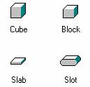
Some of the 3D solids in the Shapes catalog
|
Hole shapes remove part of your model. |
The Shapes catalog also includes several hole shapes. You drop these holes to remove parts of solid shapes. For example, you can use the |
H Block hole to carve a window out of a solid wall. You'll learn more about using holes in the next chapter, "Building models."
Some of the holes in the Shapes catalog
Along with geometric shapes and holes, you can add text to your 3D documents. To create text in a 3D scene, you drag a text shape out of the Text catalog. This text has many of the same capabilities of other 3D shapes in TriSpectives. For more on text, see Chapter 5.
You can also create 2D shapes in your models. You can leave these shapes in 2D or convert them into 3D. For details, see Chapter 4.
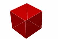
In TriSpectives, every model begins with a single shape. You drag it from the Shapes catalog into the scene, add other shapes, and then edit them to get the image you want.
u To create a shape, drag the Cube icon from the Shapes catalog and drop it in the scene.
![]()
Cube shape
|
|
If the shape is too big or small when it appears, use the Fit Scene tool. See "Using the camera tools" later in this chapter for details. |
|
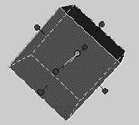
The anchor is where shapes join. |
Every shape has an anchor, the point where two shapes join. Since you have only one shape, the anchor is not useful yet. When you |
begin making models, though, the anchor can be indispensable. It provides a point of reference as you position shapes relative to each other in your model.
The
outline on the surface of the cube means it is selected.
In computer jargon, the cube is now active,
ready to be acted upon. The shape or model you drop in a 3D scene is selected
by default.
|
|
You select shapes and other screen elements, and cancel their selections, with the Select tool. When you cancel the selection of a shape or model, the outline disappears from it. |
u To cancel the selection of the cube:
Choose the Select tool if it's not active.
Click anywhere in the gray scene other than on the cube.
The outline disappears from the cube, meaning it's not selected anymore. Once you choose the Select tool, every click of your mouse selects an object or cancels a selection.
u To select the cube again, click on it.
The cube appears in outline. Once you've selected a shape, you can move it, resize it, and change its color, among other things.
The remaining sections in this chapter describe some basic shape operations, but first we need to explain a crucial part of selecting a shape: its editing mode.
The editing mode you choose determines what you can do with your shape or model. TriSpectives has three editing modes, which let you work at the level of detail you want. By clicking continually in the same spot on a model, you "drill down " to the level you need.
For example, click once on a model to enter Model mode. At this level, all your commands affect the entire model. Click again in the same spot to move to IntelliShape mode and change individual shapes in the model. Click a third time in the same spot to move to Surfaces mode, where you can revise particular surfaces and edges.
The following paragraphs describe each editing mode. You can return to Model mode at any time by clicking the background of the page or scene and then clicking the model again.
Model mode . When you dragged the shape into the scene and then clicked it, the shape appeared outlined in blue. The blue outline tells you the shape is in Model mode, so the decisions you make affect the entire model. By default, your shapes begin in Model mode. Since the model at this point is only one IntelliShape, the distinction is not important yet.
IntelliShape mode. If you click a model a second time in the same spot, it appears in white or yellow outlines with red handles. This is IntelliShape mode, as shown in the illustration in the next section, "Modifying a shape." In IntelliShape mode, your actions affect only the selected shape. Use the red handles to resize it. Click other shapes within a model to remain in IntelliShape mode and select different shapes.
Surfaces mode . The third time you click a model in the same spot, the particular surface you select appears in green outline. You are now in Surfaces mode. The actions you take, such as coloring and other surface finishing, affect only the selected surface or edge. Click different faces of the cube to select different surfaces. Note how the outline changes. Also try selecting an edge or corner.
As you work with TriSpectives, you'll probably have times when you want to work with one mode exclusively. Use the Selection toolbar to specify the editing mode.
u To choose an exclusive editing mode:
Open the Selection toolbar if it isn't visible.
From the View menu, choose Toolbars. In the resulting dialog box, click the box next to Selection and then choose OK.
Click the appropriate tool.
|
|
If
you want to work with IntelliShapes only, click the Edit IntelliShapes tool . This tool is shown at left in the
illustration. |
If you don't select a tool, TriSpectives uses Model mode . You can then change editing modes by clicking and "drilling down" to the level of detail you need, as explained above.
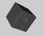
TriSpectives helps you to see which editing mode is selected each time you drag a shape from the catalog.
In Model and Surfaces modes, the pointer has a miniature 3D shape next to it.
In IntelliShape mode, the pointer appears with a miniature 3D shape that has sizebox handles.
The shape you drag in from the Shapes catalog is just a starting point. Once it's in the scene or page, you can do practically anything you want with it. In TriSpectives it's easy to change the size of a shape. Just grab it by a handle and drag.
![]()
![]()
Cube with shape handles
|
Drag a handle to resize a shape. |
The handles are the red, pin-like objects you see in IntelliShape mode. These handles let you change the size of the shape by |
expanding or contracting it.
u To change the size of a shape using a handle:
|
|
Choose the Edit IntelliShapes tool or click the shape until the handles appear. |
You must be in IntelliShape mode to resize a shape.
Click the shape if it isn't selected.
Place the mouse pointer on a handle.
When the pointer becomes a hand (and the handle changes from red to yellow), drag the handle in or out.
Try dragging various handles to see the ways you can resize the cube. You begin to get the idea of the versatility of TriSpectives.
The handles control the shape's sizebox, a frame that encloses every IntelliShape and shows its dimensions. The sizebox appears in white outline. Dragging a handle alters a face of the sizebox.
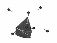
Some IntelliShapes have circular orientations, such as the sphere, the pie, and the torus. You'll notice these shapes have an extra handle, which is square. When you drag this handle, you move in a plane around an axis to increase or decrease the apparent volume of the shape.
For example, the torus shape looks like a donut. By dragging with the square handle, you can remove half the torus' volume to create the handle of a briefcase. You can drag a pie shape by the square handle and convert it from a wedge to half a pie, and finally to an entire pie (or cylinder). The following procedure shows you how.
u To change the size of the pie shape using the square handle:
Choose the Shapes catalog and then drag the pie shape into the scene.
|
|
Choose the Edit IntelliShapes tool or click the shape until the handles appear. |
You must be in IntelliShape mode to resize a shape.
Place the mouse pointer on the square handle.
This handle appears in the following illustration.
![]()
When the pointer becomes a hand, drag the square handle away from the pie shape.
As you drag, the handle moves in a circle and the pie grows larger. If nothing happens, try dragging in the other direction.
|
|
Note: Whenever you use the spin Shape tool to create a 3D custom shape, it has a square handle. See Chapter 4 for details. |
If you drag the wrong shape into a scene or decide you don't need the shape for your model, you can delete it from the scene. For example, we only needed the pie shape to show you the square handle. Now you can get rid of it.
u To delete a shape, right-click on it in Model mode or IntelliShape mode and then choose Delete from the pop-up menu.
You can also delete a selected shape by pressing the Delete key on your keyboard or by selecting Clear from the Edit menu.
The shape is still available in the Shapes catalog if you need it later.
Once you start building models, use IntelliShape mode to move particular shapes. Use Model mode to move the entire model.
Since your current model consists of only one cube shape, you must be in Model mode to move it.
u To move the cube shape within the scene:
Switch to Model mode.
You can go to Model mode by clicking the Edit IntelliShapes tool to turn it off, or use the TriSpectives menu. From the Edit menu, choose Shape Edit Mode. From the resulting pull-right menu, choose All Shapes. This is the same as Model mode.
Click the cube if it isn't selected.
Drag the cube to a new place in the scene.
When you work in a 3D scene, the objects in it have no fixed position. Think of these shapes as weightless, floating in space.
|
Use the camera tools to see shapes and models from different perspectives. |
To see a model from a different perspective or viewing angle, use the TriSpectives camera tools. These tools let you observe the 3D scene from any direction or distance. The camera is aimed at a particular point in space; by using the camera tools, you can change |
its target point. You also change your viewpoint.
Keep in mind as you use the camera tools that the shapes themselves are not moving. You're adjusting your viewpoint and the camera's target point. To move shapes, see the previous section.
![]()
The following paragraphs describe all nine TriSpectives camera tools. These tools work only in a 3D scene. On a 3D page, the tools are dimmed.
|
|
Use the Orbit Camera tool to view the 3D scene from any angle. When using this tool, the scene seems to spin as you circle it. |
u To move the camera in a circle around the cube:
1 Choose the Orbit Camera tool.
The pointer becomes a hand enclosed by a circular arrow.
2 Move the pointer to the top of the scene, above the model.
3 Click and drag the pointer straight down.
The camera begins to circle around the cube. The cube is not moving, but your viewpoint is. If you drag the pointer to the end of the scene, let go of the mouse button and repeat steps 2 and 3. You might have to drag a couple of times to completely circle the cube.
Play around with the Orbit Camera tool to get the feel of it. You can drag the mouse horizontally, vertically, and diagonally until you have any 3D viewpoint you want.
|
|
This tool pans the camera back and forth, or up and down, in a 2D plane in front of the model. |
u To pan the camera left to right in front of the cube:
1 Choose the Pan Camera tool.
The mouse pointer becomes a circle of arrows, indicating that you can move in all four 2D directions.
2 Move the pointer to the left of the model.
3 Drag the mouse to the right.
Your viewpoint seems to pass by the cube, as if it were on the roadside and you were slowly driving past it. If you drag the pointer far enough, the cube disappears altogether. You can also pan the camera vertically by dragging the pointer up and down.
When you use the Pan Camera tool, your viewpoint and the camera's target point move synchronously. You can see this by panning and then using the Orbit Camera tool.
|
|
If you panned past the cube far enough in the previous example, the cube might have disappeared. To make it reappear in your view, use the Fit Scene tool. This tool automatically moves the camera's target point and your viewpoint to the center of the cube. As a result, the shape or model fills the scene. |
u To make the cube fill the viewing area, choose the Fit Scene tool and then click anywhere in the scene.
|
|
Use the Target Camera tool to reposition the camera's target point so a point on the model is centered within the scene. |
u To center a particular point on the surface of a model, click the Target Camera tool and then click the point you want to center.
The point you select is used as the focal point for the Orbit Camera tool. Also, the distance from the camera to this point affects the sensitivity of the Dolly Camera and Walk Camera tools. If you find that your viewpoint changes too quickly when using these tools, try selecting a different point on the model with the Target Camera tool.
Clicking the scene background has no effect with the Target Camera tool.
|
|
Like the Fit Scene tool, this tool widens or narrows the angle of your camera. The Zoom Camera tool, however, lets you control the angle. The shape or model looks bigger or smaller as you zoom. |
u To zoom in on the cube:
1 Choose the Zoom Camera tool.
The mouse pointer changes to a magnifying glass with arrows. The top arrow is bigger than the bottom one, meaning you drag up to zoom in and down to zoom out.
2 Move the pointer under the cube and slowly drag the mouse toward the top of the window.
Drag until you get so close that the cube's edges disappear.
Drag the mouse in the opposite direction to zoom out and return to your original view.
|
|
This tool is like Zoom Camera, except that you zoom in on a particular area of the shape or model. This tool is useful when you want to select or manipulate a small shape in a model. |
u To zoom in and make a small object fill the window:
Select the Window Zoom tool.
Move the pointer over a blank part of the scene, very close to a corner of the cube.
The pointer becomes a cross hair.
Click and drag the mouse until a small rectangle encloses a corner of the cube, and then release the mouse.
TriSpectives zooms in to make the corner fill your window.
|
|
This tool moves the camera backward and forward, making your shape or model look bigger or smaller in the process. |
u To dolly the camera toward the cube:
1 Choose the Dolly Camera tool.
The mouse pointer changes to a pair of flattened arrows.
2 Move the pointer under the cube and slowly drag the mouse toward the top of the window.
The camera moves toward the cube, making it appear larger.
Drag the mouse in the opposite direction to move the camera backward and return to your original view.
|
|
Another useful one-click tool is Look At. This tool quickly changes your viewpoint to face a single surface of a shape or model head-on. |
The Look At tool can be very helpful when you build models. If you want to place a fuse on a stick of dynamite, it helps to look directly at the top of the stick.
The Look At tool works well with large, flat surfaces such as our faithful cube. Since you've been changing your viewpoint continually while testing the camera tools, there's no telling how the cube looks at the moment. Chances are, however, you can see at least two sides, and maybe three.
u To view just one surface of the cube:
Choose the Look At tool.
The pointer becomes a hand with an outstretched index finger.
Click any visible surface of the cube.
TriSpectives automatically moves the camera so you're looking straight at the surface. Your cube suddenly looks like an ordinary 2D square. Use the Orbit Camera tool to see the cube in three dimensions again.
|
|
The last tool we describe, Walk Camera, is perhaps the most spectacular. Using this tool creates the impression you're walking through your model with a hand-held camera. You can walk along any surface and between any shapes in your model. This tool is useful when you're working with a very intricate model. |
Since the cube is only one shape, Walk Camera isn't very useful with it. To see what Walk Camera can do, create a new scene in your WorkBook and drag in a model from the Showcase catalog.
If you need help creating a scene, see "Using IntelliShapes" earlier in this chapter. To open the Showcase catalog, click the Showcase tab at the right of the window. Drag the Widow's Walk model into the scene, and then use the Look At tool to view a particular wall and orient the model.
With the model in the scene, you can use the Walk Camera tool.
u To walk on the widow's walk:
Choose the Walk Camera tool.
Click on the floor of the walk and slowly move the pointer as if you occupied its position on the model.
Is this cool or what?
TriSpectives also lets you divide a scene into two or more partitions and view a model from several angles at once. Use the new scene to view two widow's walks or click the appropriate Doc tab to return to the cube.
u To split the scene into two parts:
1 Right-click an empty area of the scene.
2 From the resulting pop-up menu, choose Vertical Split.
TriSpectives divides the scene. If you had chosen Horizontal Split, the scene would have split along a horizontal line. You can divide the scene again and again by repeating Steps 1 and 2.
To resize the two partitions, drag the bar separating them.
To make the left partition bigger, for example, drag the splitter bar to the right. The scale of the shapes and models in each view changes to match its new size.
|
|
Choose the Orbit Camera tool and drag it over the model on the right. |
|
|
Split the screen to view a scene from two or more vantage points. |
Your viewpoint changes for the scene on the right, but stays put in the scene on the left. This ability to view a scene from various viewpoints is the best use of the split screen. If you're using the |
|
cube, your screen should resemble the following illustration.
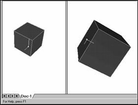
Viewing the same object from two perspectives
u To return to one view, right-click in the view(s) you want to close, and then choose Remove View from the pop-up menu.
You have a number of tools at your disposal to control a shape's appearance. Each IntelliShape has property sheets that give you access to more than a dozen categories of options.
The property sheets are different depending on which editing mode you use. To begin working through the following examples, use the cube in Model mode.
u To put the cube in Model mode and select the cube:
Click the cube until the blue outline appears.
The blue outline means you're in Model mode. You can also move to Model mode by opening the Edit menu, choosing Shape Edit Mode, and then selecting All Shapes from the next pull-right menu.
|
|
Choose the Select tool if it isn't selected already. |
Now you're ready to go to the cube's property sheet.
u To see the property sheet for the cube:
Right-click the cube.
A pop-up menu appears. This menu is different depending on the editing mode you're using.
If you're in Model mode, you can choose the Model Properties option or Style Properties.
In IntelliShape mode, you can pick IntelliShape Properties. Some of these properties are identical to the Model Properties in Model mode, but they apply only to the selected shape, not the overall model.
In Surfaces mode, you can choose Surface Properties. These properties are identical to the Style Properties in Model mode, but they apply only to the selected surface.
From the pop-up menu, choose Style Properties.
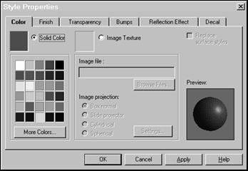
Style Properties sheet
Note the six tabs at the top of the dialog box. Click these tabs to see options for the six types of properties you can assign to your models:
Color Bumps
Finish Reflection Effect
Transparency Decal
|
Click the Apply button to refine models and keep the property sheet open. When you like the results, click OK. |
After you assign properties to a model, click the Apply button to see how the model changes. The property sheet stays open so you can make more adjustments. If you can't see the model, drag the property sheet out of the way. Once you're satisfied with the model's appearance, click OK to close the property sheet. |
The next few sections show you how assign each of the six style properties to a shape or model. For a description of every option on each of the shape's property sheets, see Chapter 3, "Dialog boxes," in the TriSpectives Reference Guide.
In TriSpectives, you can easily assign colors and textures to your shapes. Use the property sheet or just drag a color or texture from a catalog and drop it on the shape.
The Style Properties sheet should already be open from your work in the previous section. If you haven't been working along with the examples in this chapter, create a new scene and drag a cube into it from the Shapes catalog. Open the Style Properties sheet using the directions in the previous section, "Shape properties."
u To color the cube purple using the property sheet, click the purple square in the palette and then click OK.
Because you're in Model mode, the entire cube turns purple. If you were in Surfaces mode, you could make one surface purple and then assign different colors to the other five surfaces of the cube.
Now make the cube a different color by using the Colors catalog.
u To color the cube blue using the Colors catalog:
Click the Colors tab at the right of the TriSpectives window.
If necessary, use the navigation buttons to locate the Colors tab.
Use the scroll bar to move through the catalog colors until you see Blue.
Drag the Blue catalog item onto the cube and release the mouse.
Note that the pointer changed to a paint brush while you dragged the color. When you release the mouse, the cube changes color again.
|
Use the catalogs or the Style Properties sheet to add textures to a shape. |
It's equally easy to assign textures in TriSpectives. The catalogs have textures to make shapes look like plants, clouds, and stones, so you can create realistic models or absurd abstractions. As with colors, you can assign textures with catalogs or the Style Properties sheet. |
|
|
The following examples use the cube you created earlier. If you haven't been working along with the examples, create a new scene and drag a cube into it from the Shapes catalog. You must also choose Model mode and the Select tool, as explained in "Shape properties" earlier in this chapter. |
u To turn your cube into a granite pedestal using the Masonry catalog:
Click the Masonry tab at the right of the TriSpectives window.
If necessary, use the navigation buttons to locate the Masonry tab.
Use the scroll bar to move through the catalog items until you see Granit01.
Drag the catalog item onto the cube and release the mouse.
The cube is now a granite pedestal.
u To turn your granite pedestal into a cement block using the Style Properties sheet:
1 Right-click the pedestal to see its pop-up menu.
2 From the pop-up menu, choose Style Properties.
The Style Properties sheet appears with the Color tab selected. Note that the name in the Image File field is the granite texture you chose above.
Choose the Browse Files button.
The Select Image File dialog box appears. If the Masonry folder doesn't appear next to Look In at the top of the dialog, use the q and suitcase buttons to the right of the Look In field to find the Images folder. Within the Images folder, select the Masonry folder.
In the resulting list of files, double-click on Cement.tif.
The cement texture was developed in .tif file format.
Choose OK to return to the scene and view the cement block.
A texture might look good when you drop it on a shape, but you might have to experiment with its scale to make it look more realistic. For example, let's adjust the scale of the cement you created in the previous section. You'll see the difference it makes.
u To change the scale of a shape's texture:
Right-click the cement block and choose Style Properties from the pop-up menu.
The Style Properties sheet appears again with the Color tab selected. Note that the name in the Image File field is now Cement.tif.
If the Style Properties sheet is obscuring the cement block, drag it out of the way so you can see the scale change.
Choose the Box Normal image projection button if it isn't already selected.
This setting determines how the image is projected onto the selected shape or model. Your other choices are Slide Projector, Cylindrical, and Spherical.
Choose the Settings button to see the Box Projection settings.
Enter a value in the Height or Width field that is about one third the current value.
Since the Preserve Aspect Ratio check box is selected, the Height and Width will remain equal, even if you only enter a value for one.
Choose OK to apply the projection settings.
Choose OK on the property sheet.
The cement should appear to be more densely textured.
By experimenting with the scale of a texture, you can sometimes create a completely different texture. For example, you can adjust the scale of the Golf Grad texture in the Abstract catalog and create the appearance of an ice-cream sandwich.
Use the items in the Surfaces catalog to make a shape's surface appear more shiny or matted. You can also choose metallic finishes such as brass or copper.
If you want, you can assign your own modified surface finishes using the Finish settings in the Style Properties sheet.
Because these finishes tend to stand out on circular shapes, create a new scene and drag a sphere into it from the Shapes catalog. If you're not already in Model mode, you must select it, as explained in "Shape properties" earlier in this chapter.
u To assign a gold finish from the Surfaces catalog:
Click the Surfaces tab at the right of the TriSpectives window.
Use the scroll bar to move through the catalog until you see Gold2.
Drag the Gold2 item onto the sphere and release the mouse.
The sphere now looks like a Christmas ornament.
u To experiment with the finish using the property sheet:
Right-click the Christmas ornament and choose Style Properties from the pop-up menu.
Click the Finish tab at the top of the resulting Style Properties sheet.
The Finish properties appear.
Experiment by clicking the various Predefined Finishes.
Note as you choose finishes how the richness of texture and play of light changes in the Preview window. The intensity settings also change.
You can define your own finish by moving the intensity slider bars and watching the Preview window until you like the result.
Note also the Metallic Highlight check box, which gives finishes that special look of metal. Since you're already working with a gold finish, this option isn't useful at the moment.
When you like the shape's finish in the Preview window, click OK.
The Style Properties sheet closes and the finished ornament appears in the scene.
Use the transparency property to create objects you can see through, even though they occupy space in the scene. You could use transparency, for example, when creating windows for buildings.
Transparency might also be an effective tool for decorative objects such as the ornament in the previous example.
If you haven't been working along with the examples, create a new scene and drag a sphere into it from the Shapes catalog. If you're not already in Model mode, you must select it, as explained in "Shape properties" earlier in this chapter.
u To make a shape transparent:
Right-click the shape and choose Style Properties from the pop-up menu.
Click the Transparency tab at the top of the resulting Style Properties sheet.
The Transparency properties appear.
Experiment by clicking the predefined transparency settings.
As you choose settings, the shape changes appearance in the Preview window. You can set your own degree of transparency by moving the Transparency slider bar and watching the Preview window until you like the result.
When you finish, click OK.
The Style Properties sheet closes and the transparent shape appears in the scene.
Cancel the transparency setting to make the shape opaque again.
Repeat Steps 1 and 2 of this procedure and then click the predefined setting on the left, which removes any transparency. Click OK to close the dialog box.
Use the Reflection Effect property sheet to create reflections on a surface or model. An object can reflect other objects in the scene, bitmaps of images that don't appear in the scene, or both.
For the following example, you'll continue using the ornament from previous examples to see what it might look like when surrounded by Christmas tree lights.
If you haven't been working along with the examples, create a new scene and drag a sphere into it from the Shapes catalog. If you're not already in Model mode, you must select it, as explained in "Shape properties" earlier in this chapter.
u To create reflections on a shape:
Select the Ray Tracing option in the Scene Properties sheet.
Ray tracing is a form of rendering, which is the art of displaying a 3D image on a flat, 2D screen. You must select Ray Tracing to show reflections.
To select this setting, right-click in the scene background and choose Scene Properties from the pop-up menu. In the resulting properties sheet, click the Rendering tab.
In the next window, choose the Realistic Shading option and then choose Ray Tracing. Click OK to close the properties sheet.
Right-click the shape and choose Style Properties from the pop-up menu.
Click Reflection Effect at the top of the Style Properties sheet.
The Reflection Effect settings appear. If you've been working along with the ornament examples from previous sections, the Image File field shows the file name of the gold finish you assigned earlier.
If it isn't already selected, click the Reflect Image button.
This lets you create reflections on the selected shape. Since there are no other objects in the scene to reflect, we'll use a bitmap image file to create a special effect.
Choose the Browse Files button.
The Select Image File dialog appears. If the Abstract folder doesn't appear next to Look In at the top of the dialog, use the q and suitcase buttons to the right of the Look In field to find the Images folder. Within the Images folder, select the Abstract folder.
In the resulting list of files, double-click on Candy.tif.
Choose OK to return to the scene and view the ornament.
The ornament appears to reflect the multicolored lights from a Christmas tree. Have fun experimenting with the various textures; you can sometimes find new applications for them.
Some textures, such as cement, don't look realistic when their finish is smooth. TriSpectives allows you to accentuate rough surfaces by adding bumps to a shape.
For the following example, go back to the cement block you created earlier. This block is in Doc2 if you've been working through all the procedures. To see the block again, click the Doc2 tab at the bottom of the TriSpectives window.
If you haven't been working through the examples in this chapter, create a new scene, drag a cube shape into it from the Shapes catalog, and then drag a cement finish onto the cube from the Masonry catalog. If you're not already in Model mode, you must select it, as explained in "Shape properties" earlier in this chapter.
u To make the cement block bumpier:
Select the Realistic Shading option in the Scene Properties sheet.
Realistic shading is a form of rendering, which is the art of displaying a 3D image on a flat, 2D screen. You must select Realistic shading to see bumps on a shape.
To select this setting, right-click in the scene background and choose Scene Properties from the pop-up menu. In the resulting properties sheet, click the Rendering tab. In the next window, choose the Realistic Shading option. If any options under Realistic Shading are on, such as Ray Tracing, turn them off. Click OK to close the properties sheet.
Right-click the cement block and choose Style Properties from the pop-up menu.
Click the Bumps tab at the top of the Style Properties sheet.
The Bumps properties appear. Note that you can assign a texture to a shape and change the texture's scale from the Bumps properties, just like in the Color properties described earlier. You don't need to assign a texture since you already have the cement look you want.
Click the button next to Make bumps from color texture.
Drag the Bump Height slider bar up.
As you drag, watch the shape in the Preview window become bumpier. You could also create a pitted, pockmarked look by dragging the bar down and making "reverse" bumps.
The Bump Height slider bar ranges from +100 at the top
to
-100 at the bottom. Choose positive values to create bumps and negative values
to create "reverse" bumps.
When you finish, click OK to close the properties window.
The bumpy block appears in the scene.
Another fun feature to play with is decals. When you drag one from the Decals catalog onto a shape, the decal works like a sticker, applying itself to one surface. Decals are therefore different from items in the Colors and Surfaces catalogs, which cover the entire surface, shape, or model you select.
You can often use decals instead of creating parts of a complex model. For example, TriSpectives has several decals of sophisticated window designs. Rather than taking time to develop your own window, it's much easier to drag and drop a window decal on a wall.
Add a decal by dragging it from the Decals catalog or use the Decal property sheet, as described in the following procedure.
If you've been working through the examples in this chapter, use the bumpy cube you created in the previous section. Otherwise, create a new scene and drag a cube shape in from the Shapes catalog. Switch to Surfaces mode so you can apply the decal to the desired surface. If you need help switching to Surfaces mode, see "Shape properties" earlier in this chapter.
u To add a decal to a shape using the property sheet:
Right-click the surface and choose Style Properties from the pop-up menu.
Click Decal at the top of the Style Properties sheet.
The Decal settings appear.
Click the button next to Decal from selected image.
Choose the Browse Files button.
The Select Image File dialog appears. If the Decal folder doesn't appear next to Look In at the top of the dialog, use the q and suitcase buttons to the right of the Look In field to find the Decal folder.
In the resulting list of decals, double-click on bullethl.tif.
The properties sheet appears again. The file you selected appears in the Image File field. In the Preview window, the shape is marred by a large bullet hole.
Choose the Slide Projector image projection button if it isn't already selected.
This setting determines how the decal is projected onto the shape or model. Your other choices are Cylindrical and Spherical. Because you're working with a cube shape, Spherical is not a good choice: it makes the decal disappear.
To make the bullet hole look more realistic, click the Transparency Enable button.
This removes the border from the decal and makes it look more like a part of the block.
Choose OK to return to the scene and view the block.
You can move a decal along a surface or to another model surface with the Move Decal option in the Tools menu.
When you select this option, the mouse pointer appears with a miniature decal. To move the decal, click it and drag. When you finish, select the Move Decal option again to turn it off, or select a tool on one of the toolbars.
Another way to control the position of decals - as well as their size and orientation - is with the Settings button in the Decal properties sheet.
You can use the Move Decal option or Settings button to adjust any decal you apply, whether you use the Decal properties sheet or drag the decal in from the Decals catalog. In all other ways except the one explained below, decals look and work the same on model surfaces, regardless of the application method:
When you apply decals using the Decal properties sheet, the selected surface retains its original color.
When you apply a decal by dropping it on a surface from the Decals catalog, the surface's color changes to the background color of the decal. If you want, you can change the color back.
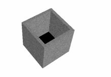
Shelling is the process of hollowing out a shape. This feature is handy, for example, for creating containers. The Shell settings let you specify the thickness of the remaining walls in the shape.
Since shelling is an IntelliShape property, you must choose IntelliShape mode before you can hollow out the shape. Up to this point you have used properties available from Model mode.
For this example we'll continue using the cement block from the previous example. If you haven't been working through the examples in this chapter, create a new scene and drag a cube shape in from the Shapes catalog. By the end of the procedure the cube will become a planter.
u To hollow out a shape using the Shelling properties:
|
|
Select the Edit IntelliShapes tool. |
Right-click the block to see its pop-up menu.
From the pop-up menu, choose IntelliShape Properties.
Select the Shell tab on the property sheet.
The Shell properties appear.
Choose the Shell this shape option.
Choose the End Section Open option.
This selection specifies which end of the shape you want kept open.
In the Wall thickness field, enter 5 as the value.
This wall thickness is appropriate for a cube with the default dimensions of 140. If you don't know the shape's dimensions, check them by selecting the Sizebox tab in the IntelliShapes properties sheet. For more details, see "Using the Sizebox properties" in Chapter 3.
Choose OK to close the properties sheet and see the hollowed shape in the scene.
|
|
You might need to use the Orbit Camera tool to see the hollow interior better. The resulting planter looks like this: |
By beveling a shape, you round off its edges. Depending on the shape, beveling can make all the difference in creating a more professional appearance.
TriSpectives offers two types of beveling:
Blend. TriSpectives rounds off the edge into a smooth curve.
Chamfer. TriSpectives cuts off a diagonal section from the edge, resulting in an angled curve.
In this example we'll make a simple cylinder shape look like a pencil eraser, just by performing a simple bevel. Create a new scene and drag in the cylinder from the Shapes catalog.
u To bevel a shape:
|
|
Select the Edit IntelliShapes tool if it isn't already selected. |
Right-click the cylinder and choose IntelliShape Properties from the pop-up menu.
Select the Bevel tab on the property sheet.
The Bevel properties appear.
Choose the End Section Edges option.
This selection specifies which end of the shape you want to bevel.
Choose the Blend option.
Type 15 as the radius for the blend.
This blend radius is appropriate for the dimensions of the default cylinder shape. If you don't know the shape's dimensions, check them by selecting the Sizebox tab in the IntelliShapes properties sheet. For more details, see "Using the Sizebox properties" in Chapter 3.
Choose OK to close the properties sheet and see the blended shape in the scene.
Adding the curved edge makes the cylinder into a pencil eraser.
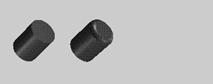
Cylinder shape before and after beveling
Another way to refine shapes is to reshape their surfaces. TriSpectives offers two types of reshaping:
Tapering. TriSpectives extends a surface by the angles you specify.
Capping. TriSpectives adds a smooth, dome-like "cap" to a surface.
In addition, you can make opposite ends of the shape match.
In this section we show you examples of capping and tapering. The first example continues the procedure from the last section, "Beveling," to create an even more realistic-looking pencil eraser from a cylinder. The second example shows you how to taper the cylinder to make it look like a tube of lipstick.
u To cap a surface:
|
|
Select the Edit IntelliShapes tool if it isn't already selected. |
Right-click the cylinder you used in the previous example and choose IntelliShape Properties from the pop-up menu.
If you did not perform the example in the previous section, "Beveling," select the Shapes catalog and drag a cylinder shape into the scene.
Select the Surface Reshaping tab.
Its property sheet appears.
Choose the End Section option under Select surfaces.
This selection specifies which end of the shape you want to reshape.
Choose the Capping option.
Type 15 as the height for the cap.
This cap height is appropriate for the dimensions of the default cylinder shape. If you don't know the shape's dimensions, check them by selecting the Sizebox tab in the IntelliShapes properties sheet. For more details, see "Using the Sizebox properties" in Chapter 3.
Choose OK to close the properties sheet and see the refined shape in the scene.
|
|
Adding the cap, in addition to the beveling you did in the last section, makes the cylinder look more like a pencil eraser. Now do a simple procedure that shows you how to taper a surface. You can use the pencil eraser you just created. |
u To taper a surface:
Repeat Steps 1 through 4 from the previous procedure.
Choose the Taper option.
Enter 45 as the taper plane tilt angle.
The angle of the plane you add to the end-section surface is 45 degrees.
Choose OK to close the properties sheet and see the refined shape.
|
|
Adding the taper changes the cylinder shape from a pencil eraser to a tube of lipstick. |
Light is another crucial component for creating realistic
models.
You can use the TriSpectives lighting tools to convey a bright, cheerful mood
or a sinister aura of mystery. For more on lighting, see its section in Chapter
6, "Illustration techniques."
For much of this chapter we've told you to experiment with shapes and textures until they look right. If you're a graphic artist, this is probably all right with you.
We realize, however, that a different camp of users out there need precision. You create drawings in which every shape, every line, has to be a certain size, and every design must meet rigorous specifications.
We haven't forgotten about those of you in the precision camp. TriSpectives has plenty of tools if you need quantitative analysis. This section introduces two such tools: shape analysis and shape statistics. We'll explain other quantitative tools as necessary throughout the rest of this guide.
Use the Shape Analysis controls to measure shapes and models as if they actually existed in physical space. You can measure a shape's area, volume, center of gravity, and moments of inertia, among other things.
u To analyze a shape:
Switch to Model mode.
Click the model until you see a blue outline. You can also move to Model mode by opening the Edit menu, choosing Shape Edit Mode, and then selecting All Shapes from the next pull-right menu.
|
|
Choose the Select tool if it isn't selected already. |
Right-click the shape you want to measure and select Analysis from the pop-up menu.
The Shape Body dialog box of the Analysis properties sheet appears, as shown in the following illustration.
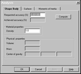
Shape Body dialog box of Analysis properties sheet
Specify the level of accuracy you want for the measurements by typing a value in the Requested Accuracy field.
For example, if you want accuracy to within 0.1%
(99.9% accuracy), type 0.1. The default value is 0.001.
Depending on the complexity of your model, TriSpectives might take a while to measure at higher levels of accuracy. If approximate values are acceptable to you, you can trade a lower level of accuracy for faster computation.
Click the Compute button to calculate the measurements shown in the property sheet.
Measurements for the shape's density, volume, mass, and center of gravity along each axis appear in their respective fields. In the Achieved Accuracy field, TriSpectives shows the actual degree of accuracy it attained for the measurements.
The other two tabs in the Analysis properties sheet - Surface and Moments of Inertia - work the same way. For example, click the Surface tab and then click Compute to see the shape's area.
For more details about the fields in the Analysis properties sheet, see Chapter 3, "Dialog boxes," in the TriSpectives Reference Guide.
Unlike the data in the Analysis properties sheet, which treat the shape as if it exists in a physical dimension, the shape statistics reveal it for the drawing it really is. These statistics, for example, tell you how many faces, loops, edges, and vertices the drawing contains.
u To see a shape's statistics:
Switch to Model mode if you're not in it already.
Click the model until you see a blue outline. You can also move to Model mode by opening the Edit menu, choosing Shape Edit Mode, and then selecting All Shapes from the next pull-right menu.
|
|
Choose the Select tool if it isn't selected already. |
Right-click a shape and select Statistics from the pop-up menu.
A window appears like the one in the following illustration, which shows statistics for the torus shape in the Shapes catalog.
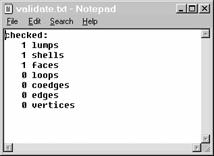
Statistics window
To save these statistics in a text file, choose Save As from the File menu of the Statistics window, enter a name for the file in the resulting dialog, and choose OK.
To close the window, choose Exit from the File menu.
|


