Dear customer,
Thank you very much for your purchasing of the 2 way car alarm products we manufactured.
1. This product is designed to install on all 12V universal vehicle. The system possesses multi-functions. For your understanding about the product, read the instruction carefully to implement its features fully.
2. If the system manual shows note like ¡§refer Alarm function RF programmed¡¨, this function becomes effective only after installation of additional equipment as is required by the system and also needed to be program.
3. Besides the functions described in the manual, the system can also support the following products:
A) Engine Start Module: When combined with engine start module, it is possible to remote control and monitor of vehicle like engine start or shutdown (effective range about 1000 meters).
B) GSM Module (Mobile Phone Module): When combined with GSM module, if the vehicle is in an abnormal condition, system will automatically notify two-way remote. Moreover, it will send a short message (SMS) and make a phone call to inform car owner about car condition. On the phone, GSM module will automatically play voice message which tells car owner¡¦s car condition. Of course, from outside call in to the machine go through the voice message guide to make command such as system arm/disarm, door lock/unlock, engine start/ shut down etc¡K You even can use short message (SMS) to control system. The system can be programmed to hold 4 different sets of phone numbers to inform car owner. Because of using the telephone net, car owner at anytime and anywhere to know car condition.
C) Satellite Tracking Module (GSM/GPS/GIS): When combined with satellite tracking module, all the above functions in (B) GSM Module would be included in the system. Moreover, car owner can use short message (SMS) to notify location of the car. Because the system includes GIS (Geographic Information System), car owner can use the short message displays in mobile phone in order to find out the location of the car. Message also told owner car status such as if the car is on the move or not and with report of speed of the car (km/hr). When car had been lost, the message would be able to trace it. This function helps car owner to search car back without the need of E-map, PDA and other people¡¦s assistance.
u System function guide
2-way LCD Transmitter indication ¡P P ¡P P ¡P P ¡P P ¡P P¡P¡P¡P¡P¡P¡P 3
Transmitter control quick table ¡P P ¡P P ¡P P ¡P P ¡P P ¡P P¡P¡P¡P¡P 4
Remote door lock/arm ¡P P ¡P P ¡P P ¡P P ¡P P ¡P P ¡P P ¡P P¡P¡P¡P¡P¡P¡P 6
Window auto roll up ¡P P ¡P P ¡P P ¡P P ¡P P ¡P P ¡P P ¡P P ¡P P¡P 6
Defective zone bypass ¡P P ¡P P ¡P P ¡P P ¡P P ¡P P ¡P P ¡P P¡P¡P¡P¡P 6
Remote door unlock/disarm ¡P P ¡P P ¡P P ¡P P ¡P P ¡P P ¡P P¡P¡P¡P 6
Dome light ¡P P ¡P P ¡P P ¡P P ¡P P ¡P P ¡P P ¡P P ¡P P ¡P P ¡P P¡P¡P¡P¡P 6
Security diagnostic report ¡P P ¡P P ¡P P ¡P P ¡P P ¡P P ¡P P¡P¡P¡P 6
Auto relocked ¡P P ¡P P ¡P P ¡P P ¡P P ¡P P ¡P P ¡P P ¡P P ¡P P¡P 6
Door auto lock/unlock upon ignition ¡P P ¡P P ¡P P ¡P P ¡P P¡P 7
Sensor by pass ¡P P ¡P P ¡P P ¡P P ¡P P ¡P P ¡P P ¡P P ¡P P ¡P P¡P¡P¡P 7
Auto arm ¡P P ¡P P ¡P P ¡P P ¡P P ¡P P ¡P P ¡P P ¡P P ¡P P ¡P P ¡P P 7
Remote alarm audible/mute mode ¡P P ¡P P ¡P P ¡P P ¡P P ¡P P 7
Remote valet ON /OFF mode ¡P P ¡P P ¡P P ¡P P ¡P P ¡P P ¡P P¡P 8
Remote check car status ¡P P ¡P P ¡P P ¡P P ¡P P ¡P P ¡P P ¡P P¡P 8
Remote car search ¡P P ¡P P ¡P P ¡P P ¡P P ¡P P ¡P P ¡P P ¡P P¡P¡P¡P¡P¡P 8
Remote active channel # 1 ¡P P ¡P P ¡P P ¡P P ¡P P ¡P P ¡P P¡P¡P¡P¡P¡P 8
Remote anti-carjack ¡P P ¡P P ¡P P ¡P P ¡P P ¡P P ¡P P ¡P P ¡P P¡P 9
Switch-controlled anti-carjack standby and cancel ¡P P¡P¡P¡P¡P¡P 9
Stop and go ¡P P ¡P P ¡P P ¡P P ¡P P ¡P P ¡P P ¡P P ¡P P ¡P P ¡P P¡P¡P 10
Auto-immobilized mode ¡P P ¡P P ¡P P ¡P P ¡P P ¡P P ¡P P ¡P P¡P¡P 10
How to adjust shock sensor sensitivity ¡P P ¡P P ¡P P ¡P P¡P 11
Alarm indication ¡P P ¡P P ¡P P ¡P P ¡P P ¡P P ¡P P ¡P P ¡P P ¡P P¡P 11
Use PIN secure code procedure ¡P P ¡P P ¡P P ¡P P ¡P P¡P¡P¡P¡P¡P 12
How to change PIN code for security needs ¡P P ¡P P ¡P P¡P¡P 12
Learn codes of the new remote transmitter ¡P P ¡P P ¡P P¡P¡P¡P 13
Reminder of allowed number of remotes ¡P P ¡P P ¡P P ¡P P 13
PIN Switch test for alert L E D ¡P P ¡P P ¡P P ¡P P ¡P P ¡P P¡P¡P¡P¡P¡P¡P 14
Indicator alert L E D table ¡P P ¡P P ¡P P ¡P P ¡P P ¡P P ¡P P¡P¡P¡P¡P 14
Hopping code transition ¡P P ¡P P ¡P P ¡P P ¡P P ¡P P ¡P P¡P¡P¡P¡P¡P¡P 14
Low battery indicator for transmitter ¡P P ¡P P ¡P P ¡P P¡P¡P¡P¡P 14
Out-of-range indication ¡P P ¡P P ¡P P ¡P P ¡P P ¡P P ¡P P ¡P P¡P 15
Transmitter¡¦s button locked/unlocked ¡P P ¡P P ¡P P ¡P P¡P¡P¡P¡P 15
Transmitter light ¡P P ¡P P ¡P P ¡P P ¡P P ¡P P ¡P P ¡P P ¡P P¡P¡P¡P¡P 15
Fixed time auto-start ¡P P ¡P P ¡P P ¡P P ¡P P ¡P P ¡P P ¡P P ¡P P¡P 17
Extra engine running timer ¡P P ¡P P ¡P P ¡P P ¡P P ¡P P ¡P P¡P¡P¡P 17
u Alarm installation guide
Main system wire guide ¡P P ¡P P ¡P P ¡P P ¡P P ¡P P ¡P P ¡P P¡P¡P 18
Alarm function RF program ¡P P ¡P P ¡P P ¡P P ¡P P ¡P P ¡P P¡P¡P¡P 19
Restore RF alarm function to factory default ¡P P ¡P P ¡P P¡P¡P 19
Alarm function RF program table ¡P P ¡P P ¡P P ¡P P ¡P P ¡P P 19
Alarm function RF program table explanation ¡P P ¡P P ¡P P 20
Door lock wire diagrams ¡P P ¡P P ¡P P ¡P P ¡P P ¡P P ¡P P ¡P P¡P¡P 21
Alarm module wiring diagram ¡P P ¡P P ¡P P ¡P P ¡P P ¡P P ¡P P 22
Start function RF program ¡P P ¡P P ¡P P ¡P P ¡P P ¡P P ¡P P¡P¡P¡P¡P¡P 23
Restore RF start function to factory default ¡P P ¡P P ¡P P¡P¡P¡P 23
Start function RF program table ¡P P ¡P P ¡P P ¡P P ¡P P ¡P P¡P¡P¡P 23
Start function RF program table explanation ¡P P ¡P P ¡P P¡P¡P 23
Engine start module wire guide ¡P P ¡P P ¡P P ¡P P ¡P P ¡P P¡P¡P¡P¡P 24
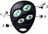
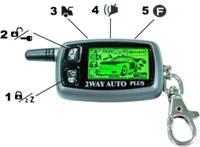
2- Way LCD transmitter One way transmitter
The 2-way LCD transmitter displays more the 20 different screen to provide real-time indications for feature activation and system status. The different display indication are shown below for reference
|
|
|
|
|
|
|
1. Disarm |
2. Audible arm |
3. Silent arm |
4. Shock trigger bypass |
5. Button locked |
|
|
|
|
|
|
|
6. Warn-away trigger |
7. Shock trigger |
8. Door open |
9. Hood open |
10. Trunk open |
|
|
|
|
|
|
|
11. Valet mode |
12. Anti-carjack |
13. Ignition key on |
14. Auto immobilize |
15. Auto arm |
|
|
|
|
|
|
|
16. Brake pedal |
17. Engine running |
18. Fixed auto start |
19. Receiver indicator |
20. Low battery |
Transmitter control quick function table
|
The two-way and one-way remotes¡¦ function table ¡P Indicates ¡§Press and release¡¨ of specified button For 2 way remote, it indicates ¡§ Press and hold specified button¡¨ for 1 second (LCD vibrates and beeps) for level shift For one way remote, it indicates ¡§ Press and hold specified button¡¨ for 1 second (LED lights green) for level shift ¡P ¡P (S1 ) Indicates ¡§Press button twice within 1 sec¡¨. |
|||||||
|
|
For 1-way and 2-way (LCD) transmitters button |
Note |
|||||
|
Function |
¡i1 |
¡i2 |
¡i |
¡i |
¡i5 |
|
|
|
Arm (Lock) |
¡P |
Ignition OFF |
|||||
|
Disarm (Unlock) |
2 ¡P |
Ignition OFF |
|||||
|
Lock |
1 ¡P |
Ignition ON |
|||||
|
Unlock |
2 ¡P |
Ignition ON |
|||||
|
All Shock Sensor by pass |
1 ¡P¡P (s1) |
At armed |
|||||
|
Valet Mode On/ Off |
1 ¡P |
At disarm mode |
|||||
|
Audible /Silent choice |
4 ¡P |
Ignition OFF |
|||||
|
Remote Engine Start& shutoff |
¡P need ESM |
Ignition OFF |
|||||
|
Fixed auto start |
¡P need ESM |
Ignition OFF |
|||||
|
Stop and go |
2 ¡P 1 ¡P |
Ignition ON |
|||||
|
Check status |
¡P |
Any time |
|||||
|
Car Finder |
¡P¡P (s1 ) |
Any time |
|||||
|
Trunk Release |
3 ¡P |
Any time |
|||||
|
Panic |
1 with 2 |
Ignition OFF |
|||||
|
Remote Anti carjack On |
1 with 2 |
Ignition ON |
|||||
|
Remote Anti carjack Off |
2 ¡P |
Any time |
|||||
|
Immobilize On/Off |
2 ¡P |
Any time |
|||||
|
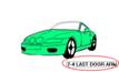
Last door arm On/Off |
2 ¡P |
Any time |
|||||
|
Adjust shock sensor |
4 ¡P |
At disarm |
|||||
|
Adjust sensor less sensitive |
¡P |
At adjust mode |
|||||
|
Adjust sensor more sensitive |
¡P |
At adjust mode |
|||||
|
Reset/lamp |
5 ¡P |
Other function |
|||||
Multi-function switch quick function table
|
Ignition must be ON |
Function |
Multi-function switch |
Process |
|
|
To turn on anti-hijack stand-by |
Press 1 time switch LED and parking light one time |
System enters anti-carjack stand-by. If triggered by door, Anti-carjack first stage is initiated |
||
|
To turn off anti-hijack stand-by |
Press 1 time switch again |
LED and parking flash three time or If ignition is turned off, anti-carjack standby mode was cleared |
||
|
Hold switch 3 sec siren chips |
If ignition turn-off is followed by siren chirps. Anti-carjack mode was cleared |
|||
|
At anti-hijack at full stage trigger turn Off |
Hold switch 3 sec siren chips |
If ignition turn-off is followed by siren chirps. Anti-carjack mode is cleared, but still in arm/lock mode |
||
|
At normal time Valet mode On/Off |
Hold switch 3 sec siren chips | |||
|
Manual disarm |
Then open car door |
Press 3 times , siren chips |
Ignition off siren chips = Manual disarm system. If ignition turn-off is followed by siren chirps. Manual disarm is done. |
|
|
Manual arm |
Press 3 times, siren chips |
If ignition turn-off is followed by siren chirps.. Then 20 sec later, system enters arm mode.. |
||
|
Ignition must be OFF |
Function |
Multi function switch |
Process |
|
|
Immobilize active reset Off |
Press 1 time switch |
Disable Immobilized function |
||
|
Reset new PIN code |
Press 4 times, siren chips |
Ignition ON Press 1 times siren chips = Set 1st new PIN code Press 1 times siren chips = Set 2nd new PIN code |
||
|
Press 5 times, siren chips |
If ignition turn-off is followed by siren chirps. System enters alarm function programmable stage. |
|||
|
Press 6 times, siren chips |
If ignition turn-off is followed by siren chirps. System enters start function programmable stage. |
|||
|
Learn codes of new remote. |
Press 7 times, siren chips |
Ignition On is followed by siren chirps system enter learn codes mode. |
||
|
Reset to alarm function factory default |
Press 9 times siren chips |
Ignition On is followed by
siren chirps. Press switch one time, system chirps, press remote button¡i |
||
|
Reset to start function factory default |
Press 10 times siren chips |
Ignition On is followed by
siren chirps. Press switch one time, system chirps, press remote button¡i |
||
u Remote door lock/arm (audio and mute) alert
When system enters arm mode, alter LED flashes to avoid thief break in. If car under security system, door, trunk, hood, ignition, brake and shock sensor would be guarded. If system had been triggered, engine can¡¦t start by using the key and siren chirps and 2-way remote gets triggered message simultaneously.
Press and release button¡e ![]() ¡f¡GSiren chirp
once (or no chips if in mute mode) with parking light flash. The car door is
locked and system enters arm mode. Refer picture No.2 or 3
¡f¡GSiren chirp
once (or no chips if in mute mode) with parking light flash. The car door is
locked and system enters arm mode. Refer picture No.2 or 3
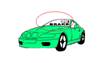
Window auto roll up¡GAfter the main system enters arm/lock.it auto roll up the electronic powered window (an accessory is require refer Alarm function RF programmed 6 times ).
Defective zone bypass¡GIf system enters arm mode. the system siren sounds long chirps 4 times and/or the remote unit sounds alarm. The main system detects a defective zone somewhere as the case of un-closed.(The remote shows triggered zones on its LCD). The system will automatically bypass the defective zone and enter arm mode. After the defective zone is corrected. The system enters full arm mode.
u Remote door unlock/disarm
When system enters disarm, security system will disable.
Press and release button¡e ![]() ¡f¡GThe
main system will unlock the door. Siren chirps 2 with flashes of parking light
¡f¡GThe
main system will unlock the door. Siren chirps 2 with flashes of parking light
(Or no chips if select ¡§Smart Siren¡¨ mode. Refer RF programmed 8 times). Refer picture No.1
Dome light¡GAfter the main system enters disarm/unlock or while in arm mode. If the alarm is triggered. The dome light will automatically turn ON. This can illuminate the car¡¦s interior for owner¡¦s checking need and is also a warning against theft. (an accessory is require refer Alarm function RF programmed 6 times).
Security diagnostic report and stage disarm¡GAfter the main system enters
disarm if siren chirps 4 times or remote unit makes 4 buzzer sounds. This
indicate the system detected some defective zones (The triggered zones will
appear in the remote LCD). And need press and release button¡e ![]() ¡fThe main system will unlock the door. The alert LED flashes until turn
on ignition by key.
¡fThe main system will unlock the door. The alert LED flashes until turn
on ignition by key.
Purpose: To indicate if the vehicle has been triggered in arm mode
Auto relock¡GAfter the main system enters disarm if the door is not opened within 30 sec after it is unlocked by the remote unit, the main system will automatically lock/arm itself (refer Alarm function RF programmed 7 times) .
Purpose: Avoid system enters disarm abnormally (for example, accidentally press remote button.) Moreover, system will automatically enter arm mode again.
Door auto lock/unlock upon ignition
In disarm/unlock into the car. When the ignition key is turned to ¡§ON¡¨ all the car doors close and pedal brake is depressed.will immediate auto lock door.(refer Alarm function RF program 2 )
Before leaving the car. If the ignition key is turned to ¡§OFF¡¨ with the key all the car doors will unlock.
Purpose: When driving, door enters auto lock/unlock according to this feature has been set up or not.
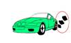
u Sensor by pass
The sensor by pass feature is the system armed the shock sensor will ineffective.
The system must be in arm mode then press and release button¡e ![]() ¡ftwice. The main system shock sensor all stage
becomes ineffective. Refer picture No.4
¡ftwice. The main system shock sensor all stage
becomes ineffective. Refer picture No.4
Purpose: Car park in a noisily environment.
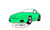
u Auto arm & (without or with lock) upon closing Last door
The auto arm feature allows the system to arm automatically without user intervention.
Press and hold button¡e2![]() ¡ffor
level shift ,then Press and
release button¡e4
¡ffor
level shift ,then Press and
release button¡e4 ![]() ¡fto select On/Off Auto arm. If select it in ON mode
the LCD remote will show it. Refer picture No.15
¡fto select On/Off Auto arm. If select it in ON mode
the LCD remote will show it. Refer picture No.15
When auto arm mode is ON¡GClose all the doors first. Then turn ignition to OFF. Open the door to leave out and close it. Siren will sound as confirmation the system has entered 10 sec countdown before auto arming is activated.(auto arm with door-lock or without locking refer Alarm function RF program 4 ).
Purpose: Without using hand to control remote, the system enters arm mode itself.
At below situation the auto arm function will disable.
A) If the car any door is opened while the ignition is form ON to OFF .
B) During into 10 sec countdown the door close twice.
Purpose: Remind user that system enters auto arm and door has been lock.
u Remote alarm audible/mute mode
When remote system, the siren can be selected audible/mute mode Refer picture No.2 or 3.
Ignition must be at OFF position. Press and release button¡e ![]() ¡fto select the audible or
mute alert modes.
¡fto select the audible or
mute alert modes.
If system choose ¡§audible mode¡¨, siren sounds different chirps depending on remote command.
If system choose ¡§mute mode¡¨, siren will not response with sound against any remote command except for car search.
u Remote valet ON /OFF mode
When valet turn ON, the system¡¦s all functions are inoperative except for the remote door lock/unlock and trunk releases and check search car remain operable
The system must be in disarm mode. Press and hold button¡e1![]() ¡ffor
level shift ,then Press and
release button¡e1
¡ffor
level shift ,then Press and
release button¡e1![]() ¡fto
select On/Off valet On or OFF. If select it in ON mode the LCD remote will show
it. Refer picture No.11
¡fto
select On/Off valet On or OFF. If select it in ON mode the LCD remote will show
it. Refer picture No.11
Purpose: Avoid others to make unnecessary commands. For example, friends or repairer play your remote.
u Remote check car status
Press and release button¡e3![]() ¡fto check the current car status. The parking light
flashes 3 times.
¡fto check the current car status. The parking light
flashes 3 times.
The current car status will show on remote LCD.
u Remote car search
Press and release twice
button¡e ![]() ¡fThe system siren chirps 6
times with 6 flashes light to help easily locate the car.
¡fThe system siren chirps 6
times with 6 flashes light to help easily locate the car.
u Remote active channel # 1
Press and hold button ¡e3![]() ¡ffor level shift ,then Press
and release button¡e3
¡ffor level shift ,then Press
and release button¡e3![]() ¡fTo active channel #1 (for example) trunk release. The
parking light will flash. Refer picture No.10 (refer Alarm function RF
program 9 ).
¡fTo active channel #1 (for example) trunk release. The
parking light will flash. Refer picture No.10 (refer Alarm function RF
program 9 ).
Purpose: User can use this function in order to control car equipments.
u Remote panic
Ignition must be at OFF position.
Press and hold ¡e ![]() ¡fwith¡e
¡fwith¡e ![]() ¡fbutton together , the parking light flashes 3 times
and siren chirps 3 times. The system auto into arm and lock mode.
¡fbutton together , the parking light flashes 3 times
and siren chirps 3 times. The system auto into arm and lock mode.
Purpose: To panic and avoid trespass.
u Remote anti-carjack
Ignition must be at ON position.
Press and hold¡e ![]() ¡fwith¡e
¡fwith¡e ![]() ¡fbutton simultaneously. The system will enter full
stage of anti-carjack mode.
¡fbutton simultaneously. The system will enter full
stage of anti-carjack mode.
While the remote anti-carjack is being activated, press and release
button¡e ![]() ¡fbutton to disable this function.
¡fbutton to disable this function.
Purpose: Engine will shutdown and can not start any more when car has been robbed.
u Switch-controlled anti-carjack standby and cancel
Turn ON/OFF anti-carjack at standby mode¡G
To turn ON anti-carjack standby mode¡GIgnition must be at ON and with all the doors closed ; if push multi function switch one time ,the system will enter anti-carjack standby mode.
Disable anti-carjack at standby mode¡GJust turn off ignition without opening the car door. The system will jump out of anti carjack standby mode.
To trigger anti-carjack mode¡G
Triggering of anti carjack first stage mode¡GDuring anti-carjack standby mode. If the door is opened and close, the system enter anti-carjack trigger first stage mode. The parking light flashes for 30 sec to show first stage mode is initiated but the siren did not chirps the engine is running normally at this stage. If first stage mode didn¡¦t interrupted on time, the system will enters second stage anti-carjack mode. Refer to picture No.12
Enter second stage of anti-carjack mode¡GFollow first stage system will auto into anti-carjack second stage mode the parking light flashes with siren chirps for 30 sec when this stage initiates. Engine will keep on running. If this stage is not interrupted, full anti carjack function will be triggered.
To disable first and second stage
anti-carjack mode¡GPress and release remote button¡e ![]() ¡for (press and hold multi function switch 3 sec. the siren chirps then turn ignition OFF). The system will jump out of
anti carjack mode.
¡for (press and hold multi function switch 3 sec. the siren chirps then turn ignition OFF). The system will jump out of
anti carjack mode.
Enter full stage of anti-carjack mode¡GFollow second stage system will auto into anti-carjack full triggering stage mode. system have A¡BB kind of state.(refer alarm RF programmed 11 ).
A) Anti-carjack safe mode¡GThe parking light flashes with siren alert which time if brake pedal is depressed the engine runs chokes for 45 sec then shuts down the engine. If in this time the ignition still at ON position the parking light and siren continuous flashes and alert.
Note¡GSelect safe mode the main unit orange/violet wire needs connect to pedal brake switch
B) Anti-carjack auto mode¡GThe parking light flashes with siren alert the engine runs chokes for 45 sec then shuts down the engine. If in this time the ignition still at ON position the parking light continuous flashes and siren alert.
To disable full stage of anti-carjack mode¡GThe system have A¡BB kind of way to turn OFF full stage of anti-carjack ( refer alarm RF programmed 5 to controlled by secure PIN code or not ).
A) For system uncontrolled by PIN code¡GPress and release remote button¡e ![]() ¡fbutton (or) press & hold multi function switch for3 sec. Turn ignition OFF when siren chirps. Anti-carjack triggering
mode is disabled but system still remains in arm mode.
¡fbutton (or) press & hold multi function switch for3 sec. Turn ignition OFF when siren chirps. Anti-carjack triggering
mode is disabled but system still remains in arm mode.
B) For system controlled by secure PIN code¡GAnti-carjack triggering can only be done by means of secure PIN code. Refer to secure PIN code procedure.
u Stop and go
To identify engine is running by key and ignition at ON position
Open the door then get off the vehicle and don¡¦t close the door.
Press and release button¡e ![]() ¡fthen close all the car doors.
¡fthen close all the car doors.
Press and release button¡e ![]() ¡fof the remote. The system enters arm/lock mode
bypassing shock sensor and ignition.
¡fof the remote. The system enters arm/lock mode
bypassing shock sensor and ignition.
Purpose: Car is under security system when user leave car in short period of time and engine is still running
u Auto-immobilizer mode ON/OFF
Under this mode feature engine start by the ignition key is disabled
Press and hold button¡e2![]() ¡ffor
level shift ,then Press and
release button¡e3
¡ffor
level shift ,then Press and
release button¡e3![]() ¡fto select ON/OFF auto-immobilizer mode. The LCD remote shows only valet ON mode if
valet is selected ON. Refer to picture No.14
¡fto select ON/OFF auto-immobilizer mode. The LCD remote shows only valet ON mode if
valet is selected ON. Refer to picture No.14
At auto-immobilizer ON mode the system automatically enters immobilizer mode (engine defeat relay is activated) after 30 sec from ignition OFF.
The immobilizer mode will indicated by dash LED whenever the ignition is turned ON.
To clear immobilizer activated mode¡GPress and release button¡e2![]() ¡fof
the remote unit (or) turn the ignition OFF first and then push the ¡§
¡fof
the remote unit (or) turn the ignition OFF first and then push the ¡§
Purpose: The engine start is disabled even with the ignition key. This feature give protection to car if car owner forgets to do command when leaving his car.
u How to adjust shock sensor sensitivity
System must be in disarm mode and ignition at OFF position in order to adjust shock sensor sensitivity
Press
and hold button¡e4![]() ¡ffor level shift ,then Press and release button¡e4
¡ffor level shift ,then Press and release button¡e4![]() ¡fto achieve active adjustment mode.
¡fto achieve active adjustment mode.
Press
and release button¡e1![]() ¡feach
time to adjust for lesser sensitivity
¡feach
time to adjust for lesser sensitivity
Press
and release button¡e2![]() ¡feach
time to adjust better sensitivity .
¡feach
time to adjust better sensitivity .
If
desired sensitivity is reached, Press and hold button¡e4![]() ¡ffor level shift ,then Press and release button¡e4
¡ffor level shift ,then Press and release button¡e4![]() ¡fagain to jump out of adjust mode.
¡fagain to jump out of adjust mode.
Note¡GThe
system has¡¨
u Alarm indication
In arm mode¡GIf the car detects any impact, the shock sensor¡¦s first stage is triggered. Parking light will flash. Refer to picture No.6
If the heavier impact is detected by the main system. the siren blurts for 27 sec with parking light flashing for the same time. Refer to picture No.7
If the trigger is caused by other means like door-open, trunk/hood open or ignition ¡§ON¡¨. The siren blurts 30 sec with parking light flashing for the same time and the engine run is disabled. Refer to picture No.8¡B ¡B ¡B
While the alert is being triggered in arm mode, press and release
button¡e ![]() ¡fonce to terminate alarm triggering The 2nd press and release
of button¡e
¡fonce to terminate alarm triggering The 2nd press and release
of button¡e ![]() ¡fmakes the main system enter unlock/disarm mode. The
alert LED flashes until turn on ignition by key.
¡fmakes the main system enter unlock/disarm mode. The
alert LED flashes until turn on ignition by key.
u Manual disarm
When remote had lost or broken use manual disarm function to cancel arm mode.
Need to be confirmed that system is settled in which of following situations in order to set up this function. The system have A¡BB kind of way to manual arm or disarm system ( depend alarm RF programmed 5 to controlled by secure PIN code or not ).
A) For system uncontrolled by secure
PIN code¡GWhile system at arm mode If user want to
manual to ¡§disarm¡¨ system . Turn the ignition key to ON position and
need open the door. Push ¡§
B) For system controlled by secure PIN code¡GRefer use PIN code procedure.
u Use PIN secure code procedure
1st
digit code 2nd
digit code (X)
time (Y)
time
The system had to programmed to secure PIN code mode before if
want to using PIN code
procedure to manually disarm and to deactivate the anti-hijack in
finally stage active mode. If didn¡¦t programmed to PIN code mode that can¡¦t
using PIN code to disarm system.
The system default PIN code digit number is
u How to use PIN code to disarm the system
Turn the ignition to ON position and it is necessary to open car door.
Press
and release the multi function switch (X) times (X is ¡§
Turn the ignition OFF. Then turn ON the ignition again.
Press
and release the multi function switch (Y) times (Y is ¡§
Turn the ignition OFF. After the system verifies PIN codes, it disarms itself.
The PIN code can be re-assigned by the car owner. Refer to the procedure to enter PIN setting mode and re-assign a new PIN code if desired.
u How to change PIN code for security need
To assign PIN code digit number at ¡§![]() ¡fbutton
remote unit. The siren 1 chirp to confirm.
¡fbutton
remote unit. The siren 1 chirp to confirm.
To assign PIN code digit number at ¡§![]() ¡fbutton
remote unit. The siren 2 chirp to confirm.
¡fbutton
remote unit. The siren 2 chirp to confirm.
To assign PIN code digit number at ¡§![]() ¡fbutton remote unit. The siren 3 chirp to confirm.
¡fbutton remote unit. The siren 3 chirp to confirm.
To assign PIN code digit number at ¡§![]() ¡fbutton remote unit. The siren 4 chirp to confirm.
¡fbutton remote unit. The siren 4 chirp to confirm.
To
assign PIN code digit number at ¡§![]() ¡fbutton
remote unit. The siren 1 chirp to confirm.
¡fbutton
remote unit. The siren 1 chirp to confirm.
To assign PIN code digit number at ¡§![]() ¡fbutton
remote unit. The siren 2 chirp to confirm.
¡fbutton
remote unit. The siren 2 chirp to confirm.
To assign PIN code digit number at ¡§![]() ¡fbutton remote unit. The siren 3 chirp to confirm.
¡fbutton remote unit. The siren 3 chirp to confirm.
To assign PIN code digit number at ¡§![]() ¡fbutton remote unit. The siren 4 chirp to confirm.
¡fbutton remote unit. The siren 4 chirp to confirm.
u Learn codes of the new remote transmitter
Ignition had to at OFF position.
Press multi function switch¡i7¡jtimes.
Then immediate turn ignition to ON position. The siren & LED indicator will
¡§
Press and release newly remote button¡e3![]() & 4
& 4![]() ¡fsimultaneously till the siren chirps 1 time
confirming code learning is completed.
¡fsimultaneously till the siren chirps 1 time
confirming code learning is completed.
Then other remote did process 3. To allow the main system learn coding of each transmitter. (Maximum 4 remotes can be learned by the system).
The system will automatically jump out of learning mode if no signal is received within 6 sec. from the last signal or turn OFF ignition.
Note¡GThe pre-memorized coding will be erased each time the learning mode is activated. Re-do the code learning in this case.
u Reminder of allowed number of remotes
Security reason. This allows you to know how many remotes are memorized up to date.
Turn
ignition to ON position. Press and release button¡e3![]() ¡fof remote and observe LED flash pattern. For example
2 times of flash Indicates that system has already learned 2 remote units.
¡fof remote and observe LED flash pattern. For example
2 times of flash Indicates that system has already learned 2 remote units.
Purpose: Allow car owner knows how many remotes are memorized up-to-date (Avoid others to make copy of the remote by using original remote).
u PIN Switch test for alert L E D
The system must be in disarm mode with the ignition ON
If all the switches are in good condition, opening of any of car door, trunk or hood can make the LED flash. The LED turns off when they are closed.
u Indicator alert L E D table
|
Different standby modes |
Ignition at OFF position LED blinking |
Ignition at ON position LED blinking |
|
System in arm mode |
* * * * * * * * * * |
|
|
Immobilization active |
|
Burn on |
|
Valet mode ON |
Burn on |
|
|
Engine start |
Burn on |
|
|
Fix time auto start |
** ** ** ** |
|
|
|
* * * * * * * * * * |
|
|
|
Depend how many unit and flash that |
|
|
|
If any zoom trigger will * * * * |
u Hopping code transition
This system¡¦s transmission uses hopping code technology that ensures total prevention from being counterfeited by code grabbers.
Purpose: Avoid others from being counterfeited by code grabbers
u Low battery indicator for transmitter
When low battery icon displays on the remote LCD, its battery is about to exhaust. Insert the new battery¡iAlkaline battery of size AAA is recommended ¡jRefer picture to No.20
u Monitoring standby indication
If the LCD shows flashing antenna, the remote is monitoring the car. Refer to picture No.19
After 1 minute from the system disarm, the remote stops monitoring and its antenna disappears from LCD.
Purpose: User can monitor any condition happens for the car.
u Out-of-range indication
When operator the remote¡¦s function button and sound low tone¡ebu¡fthe mean is the remote out of range from the car.
Purpose: User knows if the remote function or monitoring is out-of-range or not.
u Transmitter¡¦s button locked/unlocked
1. Press and release button¡e4![]() ¡fwith¡e1
¡fwith¡e1![]() ¡fthe remote¡¦s key pad
is locked.. Refer to picture No.5
¡fthe remote¡¦s key pad
is locked.. Refer to picture No.5
2. Press
and release button¡e4![]() ¡fwith¡e2
¡fwith¡e2![]() ¡fthe remote¡¦s key pad is unlocked.
¡fthe remote¡¦s key pad is unlocked.
Purpose: Avoid kids play remote and accidentally press remote button.
u Transmitter light
Press and release¡e![]() ¡fthe remote light will burn
few second.
¡fthe remote light will burn
few second.
Additional engine start module is required to using below function
u Remote engine start and shutdown for¡iauto gear car¡j
Pre-condition for to allow this features is
The car must be in neutral gear or parking mode
Hood must be closed. Refer to picture No.9
Don¡¦t depress pedal brake. Refer picture to No.16
Valet needs off mode. Refer picture to No.11
Press and hold button¡e2![]() ¡ffor level shift ,then Press and release button¡e2
¡ffor level shift ,then Press and release button¡e2![]() ¡fto remote engine start (or) shutdown. Refer
picture to No.17
¡fto remote engine start (or) shutdown. Refer
picture to No.17
When remote engine start and the door was closed system will enter arm and lock mode automatically.( refer start RF programmed 4 times ).
The parking light flashes slowly while the engine is running.( refer start RF programmed 6 ).
B) Engine will automatically shutdowns after its programmed runtime is over for example 5 minutes(refer start RF programmed 2 ).
While at arm mode and remote engine shutdown. The system will auto relock again For the car with the factory-installed device of auto door-unlock upon ignition.( refer start RF programmed 7 ).
u Remote engine start or shutdown for¡imanual gear car¡j
The following procedures are for system enters stop and go feature
Let engine run by ignition key. press and release¡e ![]() ¡f
¡f
The key turn ignition off while the engine is still running (Engine goes on running at this stage by system).
Then open the car door. Get off and re-close the door
Press and release¡e ![]() ¡f the system to make system enter arm/lock (Engine
will automatically shut off at this stage).The system¡¦s start is operable
afterwards. If there is any mistake in the procedures, the system¡¦s engine
start is disabled.
¡f the system to make system enter arm/lock (Engine
will automatically shut off at this stage).The system¡¦s start is operable
afterwards. If there is any mistake in the procedures, the system¡¦s engine
start is disabled.
Press and hold button¡e2![]() ¡ffor level shift ,then Press and release button¡e2
¡ffor level shift ,then Press and release button¡e2![]() ¡fto remote engine start (or) shutdown. Refer
picture to No.17
¡fto remote engine start (or) shutdown. Refer
picture to No.17
Purpose: Manual gear car owner can safely remote engine start.
u Fixed time auto-start
Press and hold¡e2![]() ¡fenter
deep command first. Then press and release¡e1
¡fenter
deep command first. Then press and release¡e1![]() ¡fagain
to select fixed auto-start time ON/OFF.
¡fagain
to select fixed auto-start time ON/OFF.
During the auto-start time ON mode, the engine will automatically start at time interval beginning from mode initiation (Example for time interval as 24¡B48¡B4¡B12 hours refer start RF programmable 3 ). Refer picture to No.18
After fixed auto-start mode is on, if brake pedal had stepped, this function would be disable and ICON would be disappear. User has to re-set the function in order to turn on fixed auto-start mode again.
Purpose: This can auto-start to do battery charging for car if it would be left over a long period without driving
u Extra engine running timer
RF programmed the function needs turn on.
Let engine run by ignition key. press and release¡e ![]() ¡fbutton.
¡fbutton.
Turn the ignition off while the engine is still running (Engine goes on running at this stage by system).
Then open the car door. Get off and re-close the door
Press and release¡e ![]() ¡fbutton the system to make system enter arm/lock
(Engine will automatically shut off at this stage).
¡fbutton the system to make system enter arm/lock
(Engine will automatically shut off at this stage).
Purpose: While engine hi-speed running and immediately turn off to protect the engine life.
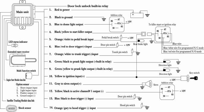
u Main system wire guide
1. Red wire: 12v (+) positive input.
2. Black wire: ground (-) input.
Connect this wire to the ground. The short black wire is connected door lock black /red harness if triggered by (-).
3. Blue wire: channel output (-) to dome light or window roll up (Refer to alarm RF Program 6th )
This wire circuit can be programmed for different mode options as below.
Mode 1and 2 for dome light¡G
While remote disarming, this wire provides 20/30sec of (-) 300mA to turn the dome light through the external relay.
Mode 3 and 4 for roll up window¡G
While remote arming, this wire provides 20/3030sec of (-)to roll up power window through the external relay.
4. Black/Yellow wire: start or ignition killer output (-)
N/C( Normally Close Mode)¡G(Refer to alarm RF Program 10th)
If this mode is chosen, there is negative output at arm and immobilized time. But there is no negative output when the system enters remote engine start even system in arm mode.
N/O( Normally Open Mode)¡G
If this mode is chosen, there is no negative output at arm and immobilized time. But there is negative output when the system enters remote engine start even system in arm mode.
Note¡G
A) If system is pre-installed without remote start module, use this wire to kill the car¡¦s start motor or ignition.
B) If system is pre-installed with remote start module, use this wire to kill the car¡¦s ignition wire.
5. Orange/violet wire input
Pedal break switch¡¦s¡GNormally rear brake light trigger negative (-) while pedal break become positive (+) connect to orange/violet . This wire needs installation effective function below
System use pedal break to do ignition upon on auto door lock.
System use pedal break to do anti-hijack programmed safe mode
System installation start module to do allowed or not allowed engine start.
6. Blue/Red wire: door switch trigger (+) (alarm RF Program 3rd)
While the door open switch trigger (+) connect with the Blue/Red. If the door closed the trigger not immediate disappear need programmed
7. Orange/White wire: trunk pin switch (-) trigger input
While trunk open switch trigger - that connect with the orange/white wire.
8. Green/Black wire: direction light (+)
output at
Output 12V(+) by internal relay for the direction light.
9. Green/Yellow wire: direction light (+)
output at
Output 12V(+) by internal relay for the direction light.
10. Yellow wire: for ignition (+) input
Connect to ignition switch area that shows + 12V when the ignition key is turned to ¡§ignition¡¨ and ¡§start¡¨ position wire.
11. Grey wire: Siren output (+)
The
main system feeds different (+) 12v of
12. Yellow /Black wire: Active channel 1output (-) of 300ma (Refer to alarm RF Program 9th)
Remote To active channel #1 this wire pulse output. The pulse time would be programmed.
13. Blue/Black wire: door pin switch trigger (-) input
While the door open switch trigger (-) connect with the Blue/Black. If the door closed the trigger not immediate disappear need programmed
14. Orange/Gray wire: hood pin switch trigger (-) input
The hood open switch trigger Connect with orange/gray .
u Alarm function RF program
Let ignition at OFF position
Press multi function switch¡i ¡jtimes,
Immediately turn ignition ON. The siren sounds 5 chips & LED indicator flashes to indicate function RF programmable mode is activated.
While in the active programming mode. Each press on multi function switch is followed by one siren chirp & one LED flash and each fifth press is followed by a long chirp. Chirping pattern enables the programmer to know which features active mode he has achieved.
When the desired function changeable level is reached, press the related button for function selection. Siren chips 1~ 4 times for confirmation. Refer to below Alarm function RF program table.(as shown in the Default change by remote¡¦s button column). The factory default is described in the V shaded background.
After 10 sec or turning off ignition, system will automatically jump out RF feature programming.
Let ignition at Off position
Press multi function switch 9 times
Immediately turn ignition. On The siren sounds 9 chips & LED flashes to confirm system¡¦s entry into standby RF function to factory default setting.
Press multi function switch 1 time The siren chips again .Then use remote button¡i ¡jto get the system restore RF features to the factory default.
|
Alarm function RF program table |
Default change by remote¡¦s button |
||||
|
M.F. switch |
Features active mode with factory default |
¡i1 |
¡i2 |
¡i3 |
¡i4 |
|
1st |
Door unlock/lock output current |
|
|
0.8 twice /0.8 |
note |
|
2nd |
Door lock/unlock upon ignition on/off |
brake pedal |
ON |
Auto Lock off unlock on |
Off |
|
3rd |
Delay door switch time |
Smart bypass for Dome light |
for Pin switch |
Pin switch delay 30 sec |
Pin switch 45 delay sec |
|
4th |
Auto arm or lock upon last door close |
Without lock |
With lock |
With lock |
With lock |
|
5th |
Manual disarm with or w/o pin code |
Without pin |
With pin code |
With pin code |
With pin code |
|
6th |
Blue wire output active |
Disarm |
Disarm |
Arm |
Arm 3 |
|
7th |
Auto rearm on/off |
On |
Off |
Off |
Off |
|
8th |
Smart siren or Horn selection |
Siren |
Smart siren |
for Horn |
for Horn |
|
9th |
Yellow/white CH # 1 output pulse time |
0. 8sec |
10 sec |
30 sec |
On/off |
|
10th |
Start or ignition killer N/C N/O |
N/C |
N/O |
N/O |
N/O |
|
11th |
Remote and Switch-controlled Anti-carjack |
Safe mode |
auto mode |
Off |
Off |
u Alarm Function RF Program Table Explanation
1st. Door lock/unlock output current time
Lock - 0,8sec; Unlock - 0,8sec (for electric system)
Lock - 3,6sec; Unlock - 3,6sec (for pneumatic system)
Lock - 0,8sec; Unlock - 2 pulse of 0,8sec (for 2 stage unlock cars)
Lock - 30sec; Unlock - 0,8sec ("comfort" output for Mercedes cars)
2nd Door lock/unlock upon ignition ON/OFF
All doors must be closed and turn ignition ON. If brake pedal is depressed, system will auto door-lock. It will immediately unlock when the ignition is turned OFF.
Car door is locked upon ignition ON. It will immediately unlock when the ignition is OFF.
Car door is not locked upon ignition ON. It will immediately unlock when the ignition is OFF.
Car door is not lock / unlock upon ignition ON/ OFF.
3rd Delay door switch time
Detect car¡¦s dome light wire Smart Bypass¡GWhich system into arm the door zoom detect effective will after the trigger disappear. If the triggered connection after 60 sec. the siren will chips 4 times and LCD show door open.
Detects door pin switch instantly¡GWhen system enters arm ,system detects door zone immediately .In other word ; after arm if door is opened, the system will auto by pass. Siren chips and LCD displays door open.
Detects door pin switch after 30 sec¡GWhen system enters arm ,system detects door zone after 30 second . In other word; after arm if door is opened, the system will auto by pass. Siren chips and LCD displays door open
Detects door pin switch after 45 sec¡GWhen system enters arm ,system detects door zone after 45 second . But after 45 sec, if the triggered zone still exists, the siren will blurt.
4th Last door close with arm and lock
Last door close with arm and door lock.
6th Blue wire output active
For dome light¡GWhile remote disarming, this wire provides 20sec of (-) 300mA current to turn the dome light ON through the external relay.
For dome light¡GWhile remote disarming, this wire provides 30sec of (-) 300mA current to turn the dome light ON through the external relay.
For window rollup¡GWhile remote arming, this wire provides 20sec of (-) 300mA current to roll up the electric window through the external relay
For window rollup¡GWhile remote arming, this wire provides 30sec of (-) 300mA current to roll up the electric window through the external relay .Auto rearm with off.
7th Auto rearmed ON/OFF
Auto rearmed ON.
Auto rearmed OFF.
8th Siren or Horn chirp time selection¡G
Siren mode¡GThe system enter audio arm mode the siren chip and disarm the siren will chip 2 times, and in silent arm mode. If triggered, the siren will not blurt.
¡§Smart Siren ¡§ mode¡GChoose this mode to allow system in audio arm mode. The siren chips upon disarming will not chips. But into disarm if siren wills 4 chips this mean is during arm mode which zoon trigger report.
Choice this mode to allow system in active arm mode as in note 1. Extra relay is required and its triggering is by horn.
Choice this mode to allow system in active arm mode as in note 1. Extra relay is required and its triggering is by horn.
9th Choice No. 12 Yellow/white wire output pulse time
Each output time at 0.8 sec. for trunk release when activated channel # 1.
Each output time at 10 sec. for user need activated channel # 1.
Each output time at 30 sec. for user need activated channel # 1.
Each output time ON/OFF. For user need activated channel # 1.
10th Choice No. 4 black/yellow wire¡¦s while start or ignition killer active¡G
N/C( Normally Close Mode)¡G
If this mode is chosen, there is negative output at arm and immobilized time. But there is no negative output when the system enters remote engine start even system in arm mode.
N/O( Normally Open Mode)¡G
If this mode is chosen, there is no negative output at arm and immobilized time. But there is negative output when the system enters remote engine start even system in arm mode.
11th Remote and Switch-controlled Anti-carjack function
Safe mode. If this mode is chosen, anti-carjack full trigger is initiated when brake pedal is depressed while in anti-carjack standby mode.
Auto mode. If this mode is chosen, anti-carjack full trigger is automatically initiated without the need to depress brake pedal while in anti-carjack standby mode.
OFF mode. If this mode is chosen, remote and switch-controlled anti-carjack function are disabled.
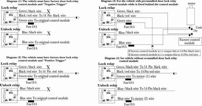
Door lock wire diagrams
Alarm module wiring diagram
Start function RF program
Let ignition at OFF position
Press multi function switch ¡i ¡j times
Immediately turn ignition ON. The siren sounds 6 chips & LED indicator flashes to indicate function RF programmable mode is activated.
While in the active programming mode. Each press on multi function switch is followed by one siren chirp & one LED flash and each fifth press is followed by a long chirp. Chirping pattern enables the programmer to know which features active mode he has achieved.
When the desired function changeable level is reached, press the related button for function selection. Siren chips 1~ 4 times for confirmation. Refer to below RF feature program table.(as shown in the Default change by remote¡¦s button column). The factory default is described in the shaded background.
After 10 sec or turning off ignition, system will automatically jump out RF feature programming.
Press multi function switch ¡i ¡j times
Immediately turn ignition. On The siren sounds 10 chips & LED flashes to confirm system¡¦s entry into standby RF function to factory default setting.
Press multi function switch 1 time The siren chips again .Then use remote
button ¡i![]() ¡jto get the system restore RF features to the factory
¡jto get the system restore RF features to the factory
Below functions need engine start module
|
Start function RF program table |
Default change by remote¡¦s button |
||||
|
M.F. switch |
Features active mode with factory default |
¡i1 |
¡i2 |
¡i3 |
¡i4 |
|
1st |
Off |
1 min |
3 min |
6 min |
|
|
2nd |
Each time remote running time |
|
|
|
|
|
3rd |
Fixed interval auto start |
hours |
48 hours |
4 hours |
12 hours |
|
4th |
Remote start with or without lock/arm |
On |
Off |
|
|
|
5th |
Remote start park light active. |
On flash |
On steady |
Off |
|
|
6th |
In arm mode after remote engine shot off the door will auto lock once. |
Off |
On |
|
|
Start Function RF Program Table Explanation
1st. Extra engine running time
Choose this mode if the extra engine running timer is not needed.
From the time ignition is turned ¡§OFF¡¨ by key, engine will keep on running for 1 min. and turn itself off automatically.
From the time ignition is turned ¡§OFF¡¨ by key, engine will keep on running for 3 min and turn itself off automatically.
From the time ignition is turned ¡§OFF¡¨ by key, engine will keep on running for 6 min and turn itself off automatically.
2nd Each time remote start running time
At this mode., remote engine starts with the engine run for¡¨
At this mode., remote engine starts with engine run for ¡§
At this mode., remote engine starts with engine run for ¡§15 ¡§min then auto shutoff.
At this mode., remote engine starts with engine run for ¡§
3rd Fixed interval auto start
At this mode., the system auto-starts with ¡§
At this mode, the system auto-starts with ¡§
At this mode, the system auto-starts with ¡§
At this mode., the system auto-starts with ¡§
At this mode; if remote engine started with door being closed , the system will automatically enter arm/lock and start engine.
At this mode; if remote engine started, the system will not automatically enter arm/lock and start engine.
5th Remote start park light active
If remote engine start the alarm system park light will auto flash.
If remote engine start the alarm system park light will auto steady on.
If remote engine start the alarm system park light will not active.
6th In arm mode after remote engine shot off the door will auto lock once .
OFF.
ON. For car with the factory-installed device of auto door-unlock upon ignition. use this option.
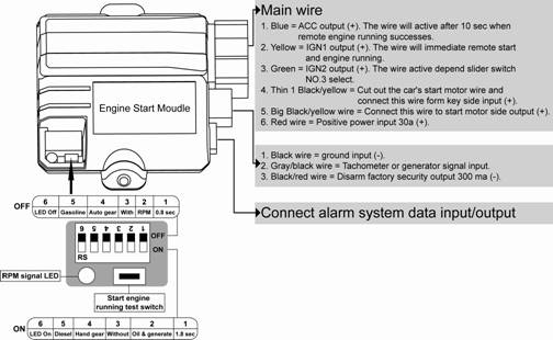
Engine Start Module wire guide
Blue wire = ACC output (+). The wire will active after 10 sec when remote engine running successes.
Yellow wire = IGN1 output (+).The wire will immediate active when remote start and engine running. Refer note:
Green wire = IGN2 output (+) The wire active depend slider switch No.3 select.
Thin l Black/yellow wire = Cut out the car¡¦s start motor wire and connect this wire form key side input (+) refer note
Big Black/yellow wire = Connect this wire to start motor side output (+)
Red wire = Positive power input
Note¡GThere are both function with thin Black/yellow & big Black/yellow
At remote stat & engine running the device will protect start motor if using key and start again.
At arm the device will killer start motor if using key and start.
Black wire = connect to ground input (-)
Gray/black wire = Tachometer or generator signal input. System will depend this wire to confirmed engine start successful or not. The wire connect car¡¦s which device have to select slider switch No. 2 depend that choice.
Switch No.2 select OFF position and system gray/black wire needs connected to car¡¦s tachometer the system will depend RPM signal to confirmed engine start successful or not.
Switch No.2 select ON position and system gray/black wire is not connected (open) the system will depend voltage to confirmed engine start successful or not. If the wire connected to generator the system will depend generator signal to confirmed engine start successful or not.
Black/red wire =Disarm factory security output (-). If the car is pre-installed with security device ¡§like transponder¡¨, this circuit is used to bypass it with the need of other external device
u RPM signal LED
The installation could using this device to easy found out car¡¦s TACH wire.
The LED will flash if slider switch No.2 choice RPM position and No.6 choice On position & Gray /black wire connect TACH signal with engine running.
u Start engine running test switch
Using this switch to test whether the remote start module is installed successful or not.
If the installation is well done, by pressing this switch one time the remote start module will activate and the engine will run. The second press on this switch the engine will stop. After this procedure, just connect the data wire of remote start module with main unit of car alarm.
Please check the installed wire if the engine can¡¦t run successfully by pressing the switch. Please pay more attention that only the remote start module can do engine running that you can connect remote start module with main unit of car alarm.
u Connect alarm system data input/output
If the Remote Start Module are installed, this connector does inter-communication works between main system.
Voltage mode crank time. OFF = 0.8 sec. ON = 1.8 sec.
Engine start sense. OFF = Tach for RPM. ON = Generate or voltage
Ignition 2 relay program. OFF= Crank output ON= Crank no output
Transmission mode OFF= automatic transmission ON=manual
Gas/Diesel mode
OFF=
RPM signal
|