ANALYSE OF THREE-PHASE INVERTER USING STEP MATRIX
Abstract. This paper describes multilevel tension inverters in witch each alternation of load tension is approximated with several levels, depending on the utilized schema and by driving circuits for electronics devices. The tension l 12412r1711m evel also depends on the used schema and by the capacities connected in parallel with the power supply. The level number depends on the conduction devices on every branch witch conduct on every clock period. The number of the levels also depends on the conducting branches number because there are inverters with 2 or 3 conducting branches. We said that we have two devices per branch because we can have two or several devices in conduction, in steady state.
Index Terms - Multilevel converter,
inverter,
INTRODUCTION
For the control of the power motor in electrical action in witch the power supply has a big value, we use the multilevel inverter (MI) or the controlled inverters. Figure 1 shows the rectifier-inverter system and the block control. In order to control the rectifier output tension we have two possibilities: control the AC power supply value and use a non controlled rectifier, or use a constant AC power supply non controlled and control the rectifier
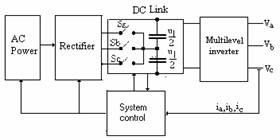
Fig. 1. Rectifier-inverter system and the block control.
The two working mod are equivalents. In Fig. 1, the DC link is a circuit with 3 switches Sa, Sb and Sc. Each of the switches must be must bi-directional and bi-operational and must be controlled in a manner that we have a constant output tension for any variation of AC power supply. In this hypothesis of keeping a constant output tension, the tension supply of the MI is constant and the analysis and simulation is made at power supply constant, [8].
The range of rectifier-inverter system and the control block is given by work frequency of semiconductor device used in system and by the control frequency of switches Sa, Sb and Sc .
This paper proposes, analyses and simulate only the inverter witch transistors because can by run so inverter three phase with two devices or three devices in conduction in steady-state. Figure 2. The difference between that inverters is make ? by driving circuit.
The analysis of MI can by made with the step matrix and the space vector [7], [10].
This paper presents three phase inverters with several levels, with two and three conducting branches, in steady-state.
For MI inverter we must specify the following:
the electronic devices that are linked to the power supply 1, 2, 3, 4, 5, 6 are called based devices, Figure 2.
The others devices are called auxiliary devices.
To analyze the MI we suppose:
the devices are ideal;
the load is formed by resistance or resistance and inductance;
every branch conducts the same time interval;
the load is with null, connected in wye;
we have a normal work commutation, when pass through one device to another, only one device switch.
Disadvantages of such converters are:
Great number of used semiconductor devices;
Use of non polarized high value capacitors.
II. ANALISE OF INVERTER WITH THREE BRANCHES IN CONDUCTION
The inverter with three branches in conduction is presented in Figure 2(a) and is called the base inverter because all inverters result from this inverter depending on the command angle a.
For 0< a <600, there is one time-slice when two devices are in conduction and one time-slice when there are three devices in conduction, in steady-state. This case is called MODE I of WORK.
For a= 600 the inverter has two devices in conduction and we have the MODE II of WORK.
For 600 < a < 1200 the inverter has two branches turned on. There are instants when all phases have null current, that is the load has no supply. This case corresponds to MODE III of WORK. In mode II and III of work, the step matrix have 12 tact's. [7], [9]. We have the inverter controlled analogous with rectifier controlled [8].
At the inverter with three branches in conduction in steady state, every branch conducts 1/2 period, that is 1800 electric's. The step matrix has six lines because there are six work tact's and six columns because there are six devices (branches) for every inverter.
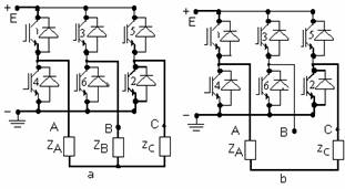
Fig. 2. Three phase inverter: (a) with 3 devices in conduction in steady-state; (b) with 2 devices in conduction in steady-state. With thicker line is represented the current flow power supply to the load
.
To write the step matrix we suppose that we have, for the first tact, the branch 1, 2 and 5 in conduction in steady-state, Figure 2(a). In this case the equivalent circuit the phase A and B is connected parallel and in serie with phase C and can write:
 (1)
(1)
where E is amplitude of power supply.
Because all phases of inverter are connected to the load, the inverter with three branch in conduction in steady-state is called the inverter without current pause.
That inverter levels are: E/3, 2E/3, -E/2 and -2E/3 and it is considered that we have an inverter with several levels or inverter with pulses.
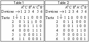
The inverter functioning is given by the step matrix that presents conduction and commutation sequence. In the step matrix, we note with 0 logic the blocking state and with 1 logic the conduction state. The commutation sequence and the conduction one is: 123, 234, 345, 456, 561, 612, after the sequence, modulo six; the step matrix is given in Table 1.
The form of tension on load results by making the equivalent circuit for every tact of period.
For the resistive and symmetrical load the current is in phase with tension and vector of current can by written:
i= ia + a ib + a2 ic (2)
where the current ia is oriented in the direction of the phase A, and
![]()
![]()
![]()
For the instant when the branch 1, 2 and 3 are turned on, we can write
 (5)
(5)
From the relations (2).. (5), results the current matrix I, the space vector i, and can by written
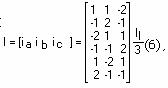
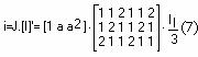
J= [1 a a2]. (8),
where I' is the transpose of the matrix current I.
The matrix I' has all elements positive because the sense of current is given by vector J.
From the relations (2)..(8) and from Table 1 results the spatial phasor presented by the Figure 3(a) witch have equal modules. The arrows of spatial phasor is placed on a hexagon peaks.
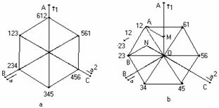
Fig. 3, Spatial phasor of current: (a) for a inverter with 3 devices in conduction in steady-state; (b) for a inverter with 2 devices in conduction in steady -state and passage from tact 12 at 23.
II. ANALISE OF INVERTER WITH TWO DEVICES IN CONDUCTION
At that inverter every devices conducts 1/3 period, that is 1200 electric's.
To write the step matrix we suppose that we have, for the first tact, the branch 1 and 2 in conduction in steady-state. In this case the equivalent circuit the phase A and C is connected in series and can write:
 (9)
(9)  (10)
(10)
where E is amplitude of power supply.
The commutation sequence and the conduction one is: 12, 23, 34, 45, 56, 61, after the sequence, modulo six; the step matrix is given in Table 2.
From the relations (9) and (10) results the current matrix I, the space vector i and can by written
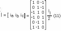
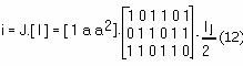
where I' is the transpose of the matrix current I.
From the relations (11)..(12) and from Table 2 results the spatial phasor presented by the Figure 3(b) witch have equal modules pause, and the manner of passage from tact 12 to 23.
Because the phases A and C is connected of the load and the phase B is not connected of the load, the inverter with two branches in conduction in steady-state is called the inverter with current pause. This case is MODE II of WORK
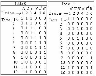
For MODE I of WORK the step matrix is given in Table 3 and result by the analyze the inverters with three or two devices in steady-state. Analogue result and the analyze for MODE III of WORK of inverter with the step matrix given in Table 4.
The spatial phasor of current for MODE I of WORK is given in Figure 4.
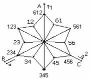
Fig. 4, Spatial current phasor for MODE I of WORK.
The spatial phasor for MODE III of WORK can be given by Figure 3(b), but is not illustrative because is not given the passage of current by zero. That passage is given bin Table 4.
III. ANALISE OF MULTILEVEL INVERTER
For the MI, the amplitude of pulse which synthesize the sinusoid is different because the power supply is not E and E/n, where n =2,3, Figure 5(a). The time interval t1, t2 and t3 are not equal and in general they are greater than other time periods. The pulses that approximates the alternance depends on the current loop from the power supply to the load. Also, the harmonic content can be reduced by driving the converter devices, by using the PWM, chopper modulation or inverter modulation (9). Choosing the modulation type depends by the converter type and the harmonic content that must be eliminated.
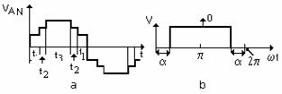
Fig.5. Wave form: (a) for multilevel inverter; (b) for controlled inverter. 07a?
It is possible that the devices witch are in steady-state in intervals ti, to by driven several times. In this case the step matrix helps to synthesize the driving circuit.
We can say that we have two or three branch in conduction state, because we have several devices on each branch turn on state.?..
For the MI, the step matrix is different because has two,
three or four devices in conduction in steady-state. In the following matrices
every matrix field has several values. To that purpose, comparing to the matrix
where we have a single device in conducting, Figure 2, every element on the
matrix step corresponds to the inverter branch in conduction state. This matrix
element will have the form ![]() where the value "x" can be only 0 or 1. In
this case we have three devices in conduction, in steady state. The first x
value represents the state for the first device by vertical and the last x
value, represents the last device by vertical. From
where the value "x" can be only 0 or 1. In
this case we have three devices in conduction, in steady state. The first x
value represents the state for the first device by vertical and the last x
value, represents the last device by vertical. From ![]() results that the base devices 1 and 2 are
turned on, and the device 11, 12 and 21,
22 and the others are blocked.
results that the base devices 1 and 2 are
turned on, and the device 11, 12 and 21,
22 and the others are blocked.
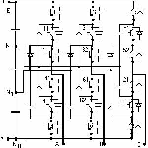
Fig.6. Five-level configuration: equivalent circuit for branches 1, 2 and 3 in conduction. 11?
The MI presented in Figure 6 can run with three branches in conduction and has three capacitors connected in parallel with the power supply [1].
The step matrix is depicted in Table 2.
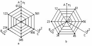
Fig.7. Spatial current phasor: (a) for Ml with three branch in conduction in steady-state; (b) for Ml with two branch in conduction in steady-state.
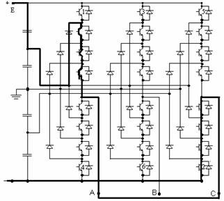
Fig. 8. Multilevel inverter. .
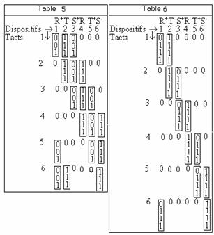
For the inverter in Figure 8, where we have four capacitors connected in parallel on the power supply, the step matrix is different. The matrix depends on the current route from power supply to load and is given in Table 6.
The spatial phasor for every MI, Figure 7, is other hexagon place in interior of spatial phasor where the power supply is E and depend by the power.
The step matrix presented by Table 1,..Table 6 are used to synthesize the driving circuit. It is possible that the devices witch are in steady-state in intervals ti, to by driven several times. In this case the step matrix helps to synthesize the driving circuit.
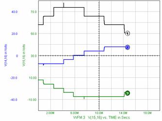
Figure 9. Simulation SPICE for MODE I of work for R=.10K
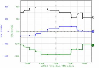
Figure 10. Simulation SPICE for MODE I of work for R=.10K and L=1MH.
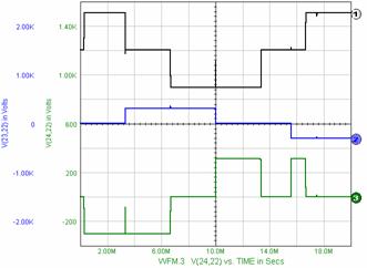
Figure 11. Simulation SPICE for MODE II of work for R=.10K.
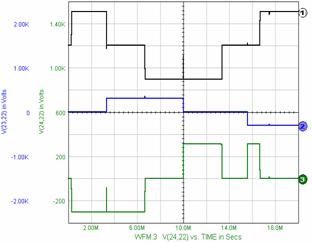
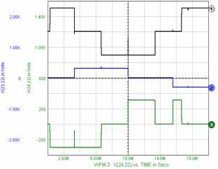
Figure 12. Simulation SPICE for MODE II of work for R=.10K and L=1MH.

CONCLUSIONS
The number of levels depends on the number of devices in conduction state on every branch on every clock period. The number of the levels also depends on the conducting branches number because there are inverters with 2 or 3 conducting devices.
This paper presents only the three phase inverters with two
branches in conduction, in steady state, and disadvantages for those converters;
Great number of semiconductor devices used;
The use of non-polarized condensers with high capacity.
For the MI with 4 level, the modules of spatial phasor is different because the power supply is not E and E/n, where n =2,3. In this case the spatial phasor for every level is other hexagon placed in interior of spatial phasor where the power supply is E.
For the inverter presented in Figure 5 or Figure 7 and other variants, the tension levels are different from E/2 and we can say that the output tension is synthesized with pulses or we have a pulse inverter.
Multi level inverters with two branches, in witch we have two or four devices in conduction, uses only three capacitors connected in parallel on power supply.
MI inverters with two branches, in witch we have two or four devices in conduction, uses only three capacitors connected in parallel on power supply.
We obtain a lower cost and lower sizes comparing to the multi level inverter witch uses four parallel-connected capacitors on power supply.
The inverter devices can be bipolar transistors but we can use IGBT transistors or better, IGBT modules.
On every multi level inverter the driving frequency can have a range from lower to high frequencies, depending on the used semiconductor device type.
So, we can drive the speed for the asynchronous machine if we use PWM or super modulation for the inverter devices.
The step matrix is used to synthesize the driving circuit, considering that a device can be drive several times per period.
At the inverter with two branches in conduction in steady-state, the tension on devices at startup is E/2 comparing with the inverter with three devices in conduction in steady-state where the tension on devices at startup is 2E/3.
The step matrix can be used for any inverter witch has on or several devices connected by branch. This device can be in conduction state or in blocking state.
The peak ? of tension in the simulation is because the time to pass from one tact to other are not equal.
If we compare the simulation for resistive and resistive-inductive load, we observe that the small tension peak appears only at the three phase inverter with three devices in conduction in steady-state.
REFERENCES
Brendan Peter Mc Grath, Donald Grahames Holmes and Thomas Lipo., Optimized Space Vector Switcing Sequence for Multilevel Inverters. IEEE Transaction on POWER ELECTRONICS, NOVEMBER 203, volume 18, nr 6, pag. 1293-1301.
Keith Corzine, Xiaomin Kuo. James R. Baker., Dynamic Average-Value Modeling of a Four-Level Drive System, IEEE Transaction on POWER ELECTRONICS, March 2003, volume 18, nr 2, pag 619- 627.
C.K. Lee et l.a., A randomizet Voltage Vector Switching Scheme for Three-level Power Inverter., IEEE Transaction on POWER ELECTRONICS, IANUARY 2002, volume 17, nr 1, pag. 94-99.
Subrata K. Mondal., Bimal K. Bose., Valentin Oleschuk Joao O. P., Space Vector Width Moldulation of Three-level inverter Extending Operation Into Overmodulation Region. IEEE Transaction on POWER ELECTRONICS, IANUARY 2003, volume 18, nr 2, pag 604- 611.
M Imecs., .a.a., Power Electronics Bucharest 1983.
Nadira Sabanovic, Asif Sabanovic, and Kouhei Ohniski, SLODIING MODES CONTROL OF THREE
PHASE EWITCHING POWER
CONVERTRES, IEE JAPAN IAS'92, 24-25
august 1992, A 6 the annual conference
of industrial application societis international session records,
Cerbulescu D., Cerbulescu C., The speed control of asyncronous motors using two inverter, IEE JAPAN IAS'92, 24-25 august 1992, A 6 the annual conference of industrial application societis international session records, Nagoya, E-3-4 pag E57-E59.
Cerbulescu D., Cerbulescu C. C THREE-PHASE RECTIFIER WITH POWER FACTOR COTROLLED, Anale of University of Craiova, serie: AUTOMATION, COMPUTERS, ELECTRONICS AND MECATRONICS, Vol I (28) Nr 1 2004 ISSN 1841-6266, pag 131-134.
Cerbulescu D., Power Static converters, Vol 1,
Cerbulescu
D., Power Static converters, Vol 2,

Cerbulescu Danila, born 1941 Mehedinti
|
