Objective |
This chapter provides practice with:
Creating a Complete Assembly
Assembling to Datum Planes
Assembling Subassemblies
In the following exercises, the boombox assembly shown in Figure 12-1 is to be created. Figure 12-2 shows a number of subassemblies that are to be created in the process.

Figure 12-
|
Most components have datum plane layers called DTM, which you can blank if desired. |

Figure 12-
This page intentionally left blank.
Exercise 12a Potentiometer Subassembly |
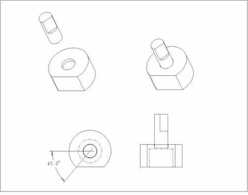
The assembly shown in Figure 12-3 is created in this exercise. The potentiometer should be assembled in such a way that the shaft can rotate by simply modifying a dimension.
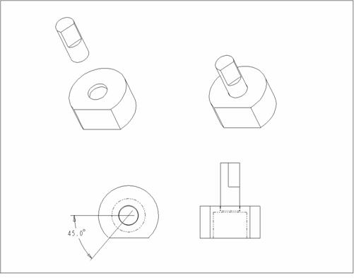
Figure 12-
Create a new assembly.
Create a new assembly called pmeter.
Create default datum planes.
Assemble the part, pot.prt, to the default datum planes.
Create an angled datum plane assembly feature.
Create an angled datum plane by choosing Feature, Create, Datum, Plane. Create the datum plane Through the axis of the pot and at an Angle to another datum plane. Enter an angular value to complete the placement of the datum plane. The potshaft part is assembled to this angled datum. The datum angle can then be modified to simulate rotation of the potshaft.
Assemble the next part.
Assemble potshaft.prt.
Mate the bottom of the shaft to the bottom of the smaller hole on top of the potshaft.
Insert the cylindrical surface of the shaft into the cylindrical surface of the hole. (Alternatively, Align both axes. Either method works.)
Although the component can be placed now, Orient the cut surface of the shaft with the angled datum plane to get the desired rotation.
When the assembly is complete, Modify the angled datum plane to verify shaft rotation.
Delete the angled assembly datum plane (and the shaft child).
Assemble the shaft again using the Make Datum option.
When defining the Orient constraint choose Make Datum and create an angled datum plane. Read the Message Window and choose the Main Window in which to create the datum plane on the fly.
Modify the angled datum plane to verify shaft rotation.
Save the assembly and Close the window.
Exercise 12b Board Subassembly |
The assembly shown in Figure 12-4 is created in this exercise.

Figure 12-
Create a new assembly.
Create a new assembly called board.
Create default datum planes.
Assemble the part, pcb.prt, to the default datum planes.
Assemble a subassembly.
Assemble one pmeter onto the pattern leader of the posts of the pcb part.
Pattern the pmeter by choosing Component, Pattern. Select the pmeter subassembly.
|
As in Part Mode, to delete a pattern choose Del Pattern. Simply choosing Delete, deletes the original component as well as the pattern. |
Because the posts where the pmeter is assembled were patterned, a menu appears with an option to create a Reference Pattern. Choose Ref Pattern, and the components automatically reference the existing pattern used for the posts.
Assemble the next part.
Assemble one button using the dimensions shown in Figure 12-4.
To pattern choose Component, Pattern. Notice that the Ref Pattern does not come up when there is no pattern to reference. Complete the pattern as learned earlier in the course.
Assemble the next part.
Assemble lcdpanel using the dimensions shown in Figure 12-4.
Save the assembly and Close the window.
Exercise 12c Exploded Assembly View |
An exploded view of the board assembly is created in this exercise.
Open the assembly called board.asm.
Open board.asm
Create a default exploded view of the Board assembly.
Choose View, Explode from the menu bar. Each component is given a default explode position relative to the references used when assembled.
Spin the model to verify that the components have exploded.

Figure 12-
Offset one of the buttons.
Choose Modify, Mod Expld, Position.
Choose Entity/Edge, Translate.
Read the Message Window and select a reference that defines the desired direction. Be aware that this causes a relationship between the button and the referenced entity. It is best to select a reference on the same component if possible.
Read the Message Window, select any button, and drag the mouse to move it. Click the left mouse button to stop the movement (or the middle mouse button to abort).

Figure 12-
|
The Explode Status can be set for components within a subassembly. Expand the model tree and individually select the components. |
Prevent the lcdpanel from exploding.
Choose Done to return to the MOD EXPLODE menu.
Choose Explode Status. Notice that the Model Tree updates with the explode status of each component/assembly.
The default options allow you to select components; this toggles their explode status. Select the lcdpanel in the assembly or in the Model Tree.
Choose Done to close the menus and update the view.
Name the modified exploded view.
Choose View, Saved Views from the menu bar. Enter a name for the view in the Saved Views dialog box.
Select the
![]() button to save the view.
button to save the view.
Select the
![]() button to close the Saved Views dialog box.
button to close the Saved Views dialog box.
Unexplode the assembly.
Choose View, Unexplode.
Retrieve the saved exploded view.
Choose View, Saved Views.
Select the name of the view you just created.
Select the
![]() button.
button.
Unexplode the assembly.
Save the assembly and Close the window.
This page intentionally left blank.
Exercise 12d CD Subassembly |
In this exercise, the CD subassembly is to be created.
Create a new assembly.
Create a new assembly called cd.
Create default datum planes.
Assemble the cd_housing to the default datum planes.
Assemble the cd_drawer part to the housing. Use an offset constraint so the drawer can be opened and closed by modifying the offset value.
After the assembly is complete, modify the offset to verify drawer movement.

Figure 12-
Save the assembly and Close the window.
This page intentionally left blank.
Exercise 12e Stereo Assembly |
In this exercise, the speaker and midsection subassemblies are to be created and are to be assembled to the top-level assembly. The final assembly is as shown in the exploded view of Figure 12-8.

Figure 12-
Create a new assembly.
Create a new assembly called lsection.
Create default datum planes.
Assemble the lcube component to the default datum planes so that it is oriented as shown in Figure 12-9.
Figure 12-
Assemble the next component.
Assemble speaker_woofer.prt so that the woofer and the lcube are flush with one another as shown in Figure 12-10. Use Mate, Orient, and Insert as necessary.
Assemble the next component.
Assemble speaker_tweeter.prt so that the tweeter and the lcube are flush with one another as shown in Figure 12-10. Use Mate, Orient, and Insert as necessary.
Save the assembly and Close the window.
Figure 12-
Create a new assembly,
Create a new assembly called rsection.
Create default datum planes.
Assemble the rcube, speaker_woofer and speaker_tweater as shown in Figure 12-11.
Save the assembly and Close the window.
Figure 12-
Create a new assembly.
Create a new assembly called midsection.
Create default datum planes.
Assemble the midcube to the default datum planes so that it is oriented as shown in Figure 12-12.
Figure 12-
Assemble the cd and board subassemblies.
Assemble the cd and board subassemblies so that the components are flush with the front face of the midcube as shown in Figure 12-13.
Save the assembly and Close the window.
Figure 12-
Create the top level assembly.
Create a new assembly called stereo.
Create default datum planes.
Assemble the midsection, lsection and rsection.
Explode the assembly.

Figure 12-
Create a bill of materials.
Create a bill of materials for the entire assembly.
Save the assembly and Erase it from memory.
This page intentionally left blank.
|
