Objective |
This chapter introduces:
Assembling with Datum Planes
Modifying in Assembly Mode
Exploded Views
Interference Checks
Bill of Materials
Just as new parts should start with default datum planes, new assemblies should too. The use of default datum planes makes the assembly more robust. They make operations such as patterning the first component and reordering subsequent components befo 11511t193l re the first, possible.
Choose Feature, Create, Datum, Plane, Default from the ASSEMBLY menu to create assembly default datum planes. They are created as three orthogonal planes named ADTM1, ADTM2, and ADTM3, as shown in Figure 6-1. The default datum planes are assembly features, not components.
Figure 6-
Datum
planes can be used as constraint references when defining component
placements. When a datum plane is
selected as a reference, the Datum Orient dialog box (as shown in Figure 6-2) appears prompting for the choice of the yellow or
red side to apply the constraint to. You
must select the red ![]() or yellow
or yellow ![]() side of the datum plane by selecting
the appropriate button. For example,
selecting the yellow side of a datum plane to be aligned with a surface forces
the yellow side to face the same direction and be coplanar to the selected
surface. Likewise, selecting the red
side of the datum plane would force the red side to face the same direction and
be coplanar to the selected surface.
side of the datum plane by selecting
the appropriate button. For example,
selecting the yellow side of a datum plane to be aligned with a surface forces
the yellow side to face the same direction and be coplanar to the selected
surface. Likewise, selecting the red
side of the datum plane would force the red side to face the same direction and
be coplanar to the selected surface.
Figure 6-
In the example in Figure 6-3, the part on the left is assembled to the assembly default datum planes shown on the right using the constraints indicated.
Figure 6-
To create this assembly, the yellow side of DTM1 of the part is aligned to the yellow side of ADTM1 of the assembly. This forces DTM1 and ADTM1 to be coplanar and face the same direction. Likewise, DTM2, yellow side, is aligned to ADTM2, yellow side, and DTM3, yellow side, is aligned to ADTM3, yellow side. These three constraints are sufficient to fully constrain the part on the assembly default datum planes as shown in Figure 6-4.
Figure 6-
Next, the pin is assembled as shown in Figure 6-5. The following three constraints are used:
Align axis A_1 of the pin to axis A_1 of the base component.
Align DTM3, yellow side, of the pin to ADTM3, yellow side.
Orient DTM2, yellow side, of the pin with ADTM2, yellow side.
Figure 6-
The pin can then be placed as shown in Figure 6-6.
Figure 6-
Finally, the u-hook is assembled as shown in Figure 6-7. The following three constraints are used:
Align DTM1, yellow side, to ADTM3, yellow side.
Mate DTM2, yellow side, to ADTM1, yellow side.
Align axis A_2 of the u-hook to axis A_1 of the bracket.
|
Aligning the yellow side of a datum plane is equivalent to mating the red side. |
Figure 6-
The pin can then be placed as shown in Figure 6-8.
Figure 6-
Could axis A_2 of the u-hook part have been aligned to axis A_1 of the pin part instead of axis A_1 of the bracket part? The answer, of course, is yes. The decision of which axis would depend on the design intent. Remember that assembly constraints result in parent-child relationships. Consider the following scenarios:
Case 1
A variety of different pin parts could be used with this assembly. In each case, the u-hook and bracket components would remain the same. If the axis of the u-hook were aligned to the axis of the pin, it would be necessary to use Redefine or Reroute when the pin component is deleted. This is because the u-hook would be a child of the pin. In this situation, it would be better to align the axis of the u-hook to the axis of the bracket.
Case 2
Again, a variety of different pin parts could be used with this assembly; however, this time, for each pin there is a corresponding u-hook. When the pin is deleted, it is necessary for the u-hook to also be deleted. It would make sense in this situation to have the u-hook as a child of the pin so that they can be easily deleted together.
There are several options for making changes to an assembly and to the components of the assembly. Choosing Modify from the ASSEMBLY menu brings up the ASSEM MOD menu, as shown in Figure 6-9. Table 6-1 shows the options from this menu.
Figure 6-
Table 6-
|
Option |
Description |
|
Mod Part |
This option is used to make changes to a selected part. It brings up the MODIFY PART menu as shown in Figure 6-9. |
|
Mod Subasm |
This option is used to make changes to a selected subassembly. It brings up the SUBMODEL menu as shown in Figure 6-9. |
|
Mod Assem |
This option is used to make changes specific to the assembly. It brings up the MODIFY ASSY menu as shown in Figure 6-9. |
|
Mod Dim |
This option is used to make changes to any dimension. It brings up the MODIFY menu as shown in Figure 6-9. |
Pro/ENGINEER allows you to create exploded views of assemblies. A default exploded view is generated based upon the placement constraints of each component. The position of components in these views can be modified by dynamically dragging components to the desired position in the view. When modifying the position of components a motion reference is selected. For example, a planar surface can be selected as the motion reference when repositioning a component in an exploded assembly view. The component is then restricted to move in a direction that is perpendicular to the planar motion reference.
The assembly in Table 6-2 is shown in a normal view, the default exploded view, and a modified exploded view.
Table 6-
|
Normal View |
Default Exploded View |
Modified Exploded View |
|
|
|
|
To create an exploded assembly view select View, Explode from the menu bar. Choose View, Unexplode to return to the normal view.
Pro/ENGINEER can check for interference between components. It reports the parts involved and the volume of interference.
To
do an interference check, select Info,
Modal Analysis from the menu bar. This brings up the Model Analysis dialog box. Select Global
Interference from the Type pull-down menu and select the ![]() button. This performs a global interference check between parts. Interfering parts are identified in the
Results section of the dialog box.
button. This performs a global interference check between parts. Interfering parts are identified in the
Results section of the dialog box.
Figure 6-
A bill of materials can be quickly generated to give a complete list of all parts in the assembly. This is done by selecting Info, BOM from the menu bar. This brings up the BOM dialog box shown in Figure 6-11.
Figure 6-
Selecting
the ![]() button displays the default bill of materials
in an Information Window for the top-level assembly. The bill of materials for the valve assembly
in Figure
6-12 is shown in Figure
6-13.
button displays the default bill of materials
in an Information Window for the top-level assembly. The bill of materials for the valve assembly
in Figure
6-12 is shown in Figure
6-13.
Figure 6-
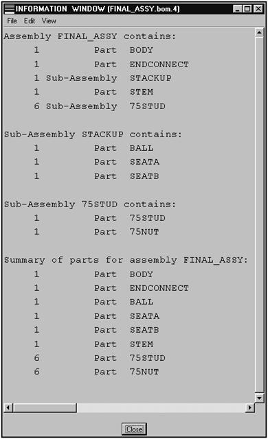
Figure 6-
This page intentionally left blank.
Exercise 6a Datum Plane Assembly |
Objective |
After you complete this exercise, you will be able to:
Assemble with Datum Planes
|
For an additional exercise on the topics covered in Chapter 6, see Appendix B, Exercise B8. |
The assembly shown in Figure 6-14 is created in this exercise. For clarity, the component datum planes are not shown.
Figure 6-
Create a new assembly.
Create a new assembly called slider.
Create assembly default datum planes.
Choose Feature, Create, Datum, Plane, Default from the ASSEMBLY menu.
Assemble the part called guide.prt.
Assemble guide.prt as shown in Figure 6-15.
Figure 6-
Choose Component, Assemble and select guide.prt.
|
Use the |
Align DTM1, Yellow side, of the component to ADTM1, Yellow side, of the assembly.
Align DTM2, Yellow side, of the component to ADTM2, Yellow side, of the assembly.
Align DTM3, Yellow side, of the component to ADTM3, Yellow side, of the assembly.
Assemble the part called shaft.prt.
Assemble shaft.prt as shown in Figure 6-16.
Figure 6-
Choose Component, Assemble and select shaft.prt.
Align Offset DTM1, Yellow side, of the component with ADTM1, Yellow side, of the assembly. Enter an offset value of [-5].
Align DTM2, Yellow side, of the component to ADTM2, Yellow side, of the assembly.
Align DTM3, Yellow side, of the component to ADTM3, Yellow side, on the assembly.
Assemble the part called handle.prt.
Assemble handle.prt as shown in Figure 6-17.
Figure 6-
Align axis A_1 of the handle with axis A_4 of the shaft.
Mate Offset DTM2, Yellow side, of the component with ADTM2, Yellow side, of the assembly. Enter an offset value of [3].
Orient the planar surface on the handle with ADTM3, Yellow side on the assembly.
Perform an interference check on the assembly.
Choose Info, Model Analysis from the menu bar.
Select Global Interference from the TYPE pull-down menu.
Accept all
the other default selections and select the ![]() button. The Results section of the dialog box should indicate an interference
between the shaft and the handle.
button. The Results section of the dialog box should indicate an interference
between the shaft and the handle.
Select the
![]() button. The information Window again identifies the interfering parts and the
volume of interference.
button. The information Window again identifies the interfering parts and the
volume of interference.
Select the
![]() buttons on the Information Window and the
Model Analysis dialog box.
buttons on the Information Window and the
Model Analysis dialog box.
Modify the diameter of the handle.
Choose Modify, Mod Part and select the handle component.
Choose Modify Dim and select the handle to display its dimensions.
Select the 1.55 diameter dimension and change it to [1.49].
Choose Regenerate from the MODIFY PART menu. Do another interference check. Is there any other interference?
Create a round on the handle without leaving Assembly Mode.
Choose Modify, Mod Part and select the handle component.
Choose Feature from the MODIFY PART menu. The PART FEAT menu that appears is the same as the FEATURE menu used in Part Mode.
Choose Create, Round, Simple, Done, Constant, Edge Chain Done.
Select the edge shown in Figure 6-18 and choose Done Sel, Done.
Figure 6-
Enter a
value of [.5] for the radius of the round. Complete the feature by selecting the ![]() button in the dialog box.
button in the dialog box.
Choose Done/Return from the PART FEAT menu and Done from the MODIFY PART menu.
Open the handle part in Part Mode. Although the feature was created while in Assembly Mode, the round is a feature of this part because the Mod Part option was used.
Figure 6-
Close this window and Activate the window containing the assembly.
Create a bill of materials.
Choose Info, BOM.
Select Top Level and the ![]() button in the BOM dialog box. The bill of materials appears in the
Information Window.
button in the BOM dialog box. The bill of materials appears in the
Information Window.
Simulate motion in the assembly.
An assembly dimension was created when the Align Offset constraint was used. Modify this dimension to simulate motion in the assembly.
Choose Modify, Mod Assem, Modify Dim and select the shaft component. Select the offset dimension that appears and change it to [0].
Choose Done from the MODIFY ASSY menu and Done/Return from the ASSEM MOD menu. Choose Regenerate, Automatic from the ASSEMBLY menu. The assembly should appear as shown in Figure 6-20.
Figure 6-
Explode the assembly.
Choose View, Explode. The default exploded view may appear as shown in Figure 6-21.
Figure 6-
Modify the position of the components in the exploded view.
Choose Modify, Mod Expld, Position.
Experiment with the options to obtain an exploded view as shown in Figure 6-22
Figure 6-
Save the assembly and Erase it from memory.
This page intentionally left blank.
|