BASIC for PIC microcontrollers Author: Nebojsa Matic
|
In this book you can find: |
|
Practical connection samples for: |
|
Temperature sensors, AD and DA converters LCD and LED displays, relays. Every example is commented in details with detailed connection scheme |
|
Program writing |
|
Learn how to write your own program, correct mistakes and use it to start a microcontroller. |
|
Instruction Set |
|
Every instruction is explained in detail with the example how to use it. |
|
MicroCode studio |
|
How to install it, how to use it |
|
MPLAB program package |
|
How to install it, how to start the first program, how to connect BASIC and MPLAB etc. |
Chapter 1
THE FUNDAMENTS OF PIC BASIC
Introduction
1.1 BASIC for PIC microcontrollers 1.2 PIC microcontrollers 1.3 First program written in PIC
BASIC 1.4 Writing and compilation of a
BASIC program
1.5 Loading a program into the
microcontroller memory
1.6 Running your program
1.7 Problem with starting your
program (what if it doesn't work)
Introduction
Simplicity and ease, which the higher programming languages bring for program writing as well as broader application of the microcontrollers, was enough to incite some companies as Microengeneering to embark on the development of BASIC programming language. What did we thereby get? Before all, the time of writing was shortened by employment of prepared functions that BASIC brings in (whose programming in assembler would have taken the biggest portion of time). In this way, the programmer can concentrate on solving the essential task without losing his time on writing the code for LCD display. To avoid any confusion in the further text, it is necessary to clarify three terms one encounters very often.
Programming language is understood as a set of commands and rules according to which we write the program and therefore we distinguish various programming languages such as BASIC, C, PASCAL etc. On the BASIC programming language the existing literature is pretty extensive so that most of the attention in this book will be dedicated to the part concretely dealing with the programming of microcontrollers.
Program consists of sequence of commands of language that our microcontroller executes one after another. The structure of BASIC program is explained with more detailed in the second chapter.
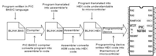
BASIC compiler is the program run on PC and it's task is to translate the original BASIC code into the language of 0 and 1 understandable to the microcontroller. The process of translation of a BASIC program into an executive HEX code is shown on the image below. The program written in PIC BASIC and registered as a file Program.bas is converted into an assembler code (Program.asm). So obtained assembler code is further translated into executive HEX code which is written to the microcontroller memory by a programmer. (programmer is a device used for transferring HEX files from PC to the microcontroller memory)
1.1 BASIC for PIC microcontrollers
As a programming language, BASIC is since long time ago known to the PC users to be the easiest and the most widespread one. Nowadays this reputation is more and more being transferred onto the world of microcontrollers. PIC BASIC enables quicker and relatively easier program writing for PIC microcontrollers in comparison with the Microchip's assembling language MPASM. During the program writing, the programmer encounters always the same problems such as serial way of sending messages, writing of a variable on LCD display, generating of PWM signals etc. All for the purpose of facilitating programming, PIC BASIC contains its built-in commands intended for solving of the problems often encountered in praxis. As far as the speed of execution and the size of the program are concern, MPASM is in small advantage in respect with PIC BASIC (therefore exists the possibility of combining PIC BASIC and assembler). Usually, the part of the program in which the same commands are executed many times or time of the execution critical, are written in assembler. Modern microcontrollers such as PIC execute the instructions in a single cycle lasting for 4 tact of the oscillator. If the oscillator of the microcontroller is 4MHz, (one single tact lasts 250nS), then one assembler instruction requires 250nS x 4 = 1uS for the execution. Each BASIC command is in effect the sequence of the assembler instructions and the exact time necessary for its execution may be obtained by simply summing up the times necessary for the execution of assembler instructions within one single BASIC command.
1.2 PIC microcontrollers
The creation of PIC BASIC followed the great success of Basic stamp (small plate with PIC16F84 and serial eeprom that compose the whole microcontroller system) as its modification. PIC BASIC enables the programs written for the original Basic stamp to be translated for the direct execution on the PIC16xxx, PIC17Cxxx and PIC18Cxxx members of the microcontrollers family. By means of PIC BASIC it is possible to write programs for the PIC microcontrollers of the following families PIC12C67x, PIC14C000, PIC16C55x, PIC16C6x, PIC16C7x, PIC16x84, PIC16C9xx, PIC16F62x, PIC16C87x, PIC17Cxxx and PIC 18Cxxx. On the contrary, the programs written in PIC BASIC language cannot be run on the microcontrollers possessing the hardware stack in two levels as is for example the case of PIC16C5x family (that implies that by using the CALL command any subroutine can be called not more than two times in a row).
For the controllers that are not able to work with PIC BASIC there is an adequate substitution. For example, instead of PIC16C54 or 58, we can use pin compatible chips PIC16C554, 558, 620 and 622 also operating with PIC BASIC without any difference in price.
Currently, the best choice for application development, using PIC BASIC are microcontrollers from the family : PIC16F87x, PIC16F62X and of course the famous PIC16F84. With this family of PIC microcontrollers, program memory is created using FLASH technology which provides fast erasing and reprogramming, thus allowing faster debugging. By a single mouse click in the programming software, microcontroller program can be instantly erased and then reloaded without removing chip from device. Also, program loaded in FLASH memory can be stored after power supply has been turned off. The older PIC microcontroller series (12C67x, 14C000, 16C55x, 16C6xx, 16C7xx and 16C92x) have program memory created using EPROM/ROM technology, so they can either be programmed only once (OTP version with ROM memory) or have glass window (JW version with EPROM memory), which allows erasing by few minutes exposure to UV light. OTP versions are usually cheaper and are used for manufacturing large series of products. Besides FLASH memory, microcontrollers of PIC16F87x and PIC16F84 series also contain 64-256 bytes of internal EEPROM memory, which can be used for storing program data and other parameters when power is off. PIC BASIC has built-in READ and WRITE instructions that can be used for loading and saving data to EEPROM. In order to have complete information about specific microcontroller in the application, you should get the appropriate Data Sheet or Microchip CD-ROM.
 The program examples worked
out throughout this book are mostly to be run on the microcontrollers PIC16F84
or PIC6F877, but could be, with small or almost no corrections, run on any
other PIC microcontroller.
The program examples worked
out throughout this book are mostly to be run on the microcontrollers PIC16F84
or PIC6F877, but could be, with small or almost no corrections, run on any
other PIC microcontroller.
1.3 First program written in PIC BASIC
In order to start program writing and application development in BASIC programming language, it is necessary to have at least one text editor, PIC BASIC compiler and according to someone's wish - a system in development on which the program is supposed to be checked. For writing BASIC program code, any text editor that can save the program file as pure ASCII text (without special symbols for formatting) can be used. For this purpose editors like Notepad or WordPad are also good. Even better solution than the use of any classical text editor is the use of some of the editors specially devised for program code writing such as Microchip's MPLAB or Mecanique's Micro CODE STUDIO.
The advantage of these program packages is that they take care of the code syntax, free memory and provide more comfortable environment when writing a program (appendices A and B describe MPLAB and MicroCODE STUDIO editors).
1.4 Writing and compilation of a BASIC program
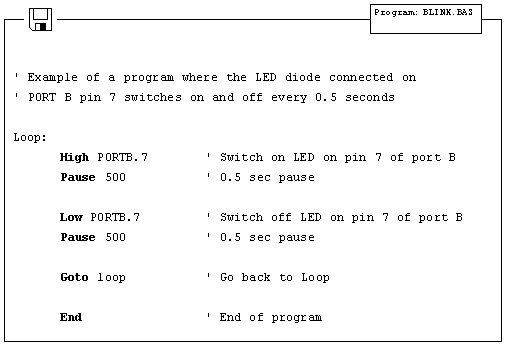
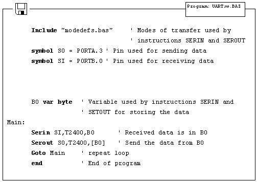
The first step is the writing of a program code in some of enumerated text editors. Every written code must be saved on a single file with the ending .BAS exclusively as ASCII text. An example of one simple BASIC program - BLINK.BAS is given.
When the original BASIC program is finished and saved as a single file with .BAS ending it is necessary to start PIC BASIC compiler. The compiling procedure takes place in two consecutive steps.
Step 1. In the first step compiler
will convert BAS file in assembler s code and save it as BLINK.ASM file.
Step 2. In the second step compiler automatically calls assembler, which
converts ASM - type file into an executable HEX code ready for reading into the
programming memory of a microcontroller.
The transition between first and second step is for a user - programmer an invisible one, as everything happens completely automatically and is thereby wrapped up as an indivisible process. In case of a syntax error of a program code, the compilation will not be successful and HEX file will not be created at all. Errors must be then corrected in original BAS file and repeat the whole compilation process. The best tactics is to write and test small parts of the program, than write one gigantic of 1000 lines or more and only then embark on error finding.
1.5 Loading a program into the microcontroller memory
As a result of a successful compilation of a PIC BASIC program the following files will be created.
- BLINK.ASM -
assembler file
- BLINK.LST - program listing
- BLINK.MAC - file with macros
- BLINK.HEX - executable file which is written into the programming memory
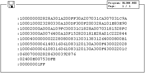
File with the HEX ending is in effect the program that is written into the programming memory of a microcontroller. The programming device with accessory software installed on the PC is used for this operation. Programming device is a contrivance in charge of writing physical contents of a HEX file into the internal memory of a microcontroller. The PC software reads HEX file and sends to the programming device the information about an exact location onto which a certain value is to be inscribed in the programming memory. PIC BASIC creates HEX file in a standard 8-bit Merged Intel HEX format accepted by the vast majority of the programming software. In the text bellow the contents of a file BLINK.HEX is given.
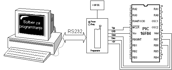
Besides reading of a program code into the programming memory, the programming device serves to set the configuration of a microcontroller. Here belongs the type of the oscillator, protection of the memory against reading, switching on of a watchdog timer etc. The connection between PC, programming device and the microcontroller is shown.
The programming software is used exclusively for the communication with the programming device and is not suitable for any code writing. The one comprising text editor, software for programming microcontroller and possibly the simulator as an entity bears the name IDE i.e. Integrated Development Environment. One such environment is a Microchip's software package MPLAB.
1.6 Running your program
For correct operating of a microcontroller, i.e. correct running of a program it is necessary to assure the supply of the microcontroller, oscillator and the reset circuit. The supply of the microcontroller can be organized with the simple rectifier with Gretz junction and LM7805 circuit as shown in the picture below.
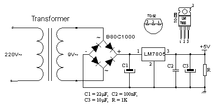
The oscillator of the microcontroller can be a 4MHz crystal and either two 22pF capacitors or the ceramic resonator of the same frequency (ceramic resonator already contains the mentioned capacitors, but contrary to the oscillator has three termination instead of only two). The speed at which the microcontroller operates i.e. the speed at which the program runs depends heavily on this frequency of an oscillator. In the course of an application development the easiest to do is to use the internal reset circuit in a manner that MCLR pin is connected to +5V through a 10K resistor. In the sequence of text the scheme of a rectifier with circuit of LM7805 which gives the output of stable +5V, as well as the minimal configuration relevant for the operation of a PIC microcontroller.
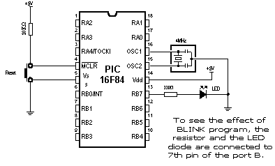
Minimal hardware configuration necessary for the operation of PIC microcontroller
After the supply is brought to the circuit structured according to the previous pictures, PIC microcontroller should look animated, and its LED diode should be twinkling once each second. If the signal is completely missing (LED diode doesn't twinkle), the check is to be done to ascertain if the +5V is present at all the corresponding tentacles on PIC microcontroller.
1.7 Problem with starting your program (what if it doesn't work)
The usual problems of bringing the PIC microcontroller into the working conditions comprise the check of few external components and inquiry into the fact whether their values correspond to the wanted ones or whether all the connections with the microcontroller have been done properly. There are some suggestions that may be useful in order to help bringing to
Step 1. Check whether the MCLR
pin is connected to 5V or over a certain reset circuit or simply with 10K
resistor. If the pin remains disconnected, it's level will be
"floating" and it may work sometimes, but usually it won't. Chip has
power-on-reset circuit, so that appropriate external "pull-up"
resistor on MCLR pin should be sufficient.
Step 2. Check whether the connection with the resonator is stable. For
most PIC microcontrollers to begin with 4MHz resonator is well enough.
Step 3. Check the supply. PIC microcontroller spends very little energy
but the supply must be pretty well filtrated. At the rectifier exit, the
current is direct but pulsing and as such is by no means suitable for the
supply of microcontroller. To avoid this pulsing, the electrolytic capacitor of
high order of capacitance (say 470 mF) is placed at the exit of a rectifier.
If PIC microcontroller supervises the devices that pull lot of energy from the energy source they can in their own rights provoke enough malfunctioning on the supply lines so that the microcontroller can stop working normally and start revealing somewhat strange behavior. Even seven-segmented LED display may well induce tension drops (the worst scenario is when all the digits are 8, for then LED display needs most power), if the source itself is not capable to procure enough current (for the case of 9V battery just for an example).
Some PIC microcontrollers have multi-functional entrance\exit pins, as it is the case with PIC16C62x family (PIC16C620, 621 and 622). The microcontrollers belonging to this family are provided with analogue comparators at port A. After putting those chips to work, port A is set onto an analogue mode, which brings about the unexpected behavior of the pin functions on this port. Any PIC microcontroller with analogue entrances will after reset show itself in an analogue mode (if the same pins are used as digital lines they must then be set into a digital mode).
One of the possible sources of troubles is that the fourth pin of the port A shows singular behavior when it is used as exit (because this pin has open collectors exit instead of usual bipolar state). That implies that the inscription of the logical zero on this pin will nevertheless set it on the low level, but the inscription of logical unit will let it float somewhere in between instead of setting it at high level. To coerce this pin react in a proper way the pull-up resistor is placed between RA4 and 5V. The magnitude of this resistor may be between 4.7K and 10K, depending on the intensity of the current necessary for the convected entrance. This pin functions as any other pin used as an entrance (all the pins are after reset procedure set as exits).
During the work with PIC microcontrollers more problems are to be expected. Sometimes what is being tried seems like going to work, but it doesn't happen to be the case regardless of how hard had we put an effort. Normally there is more than one way to solve something. A different angle approach may bring a solution with the same effort.
Chapter 2
BASIC ELEMENTS OF PIC BASIC LANGUAGE
Introduction
2.1 Identifiers 2.2 Labels 2.3 Constants 2.4 Variables 2.5 Sequences 2.6 Modifiers 2.7 Symbols 2.8 Direction INCLUDE 2.9 Comments 2.10 Programming line with more instructions 2.11 Transfer of a instruction into another line 2.12 Define 2.13 DISABLE 2.14 ENABLE 2.15 ON INTERRUPT 2.16 RESUME
Introduction
Next chapter describes the basic elements of a PIC BASIC language and the mode to use them in the efficient program writing. It is somewhat of an artistry to write a code that is both readable and easy to handle. Program is supposed to be understandable, before all, to the programmer himself and then later to his colleagues in charge of doing some corrections and adding as well. In the further text is given one example of the program written in a clear and manifest way.
Donja slika nema prevod
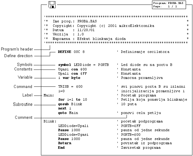
Extensive use of comments, symbols, labels and other elements supported by PIC BASIC, program can be rendered considerably clearer and more understandable what is in later corrections and enlargement of the program offering programmer a great deal of help.
In order to make it even more understandable it is advisable to separate the program into logical entities as those parts to which a jump with the goto instruction can be performed or subprograms to be called with the gosub instruction.
Labels indicating the beginning of the segments of programs should have meaning making some obvious sense. If it, say, exists such segment of a program that switches on and off LED diodes on some of the ports, the label indicating the beginning of that part of the program could well be for example "Blink" (LED diodes shine or go dark - therefore they blink) or the like.
Elements determining one BASIC program are the following:
- Identifiers
- Labels
- Constants
- Variables
- Sequences
- Modifiers
- Symbols
- Comments
- Include
- DEFINE
- _ (continuation of a instruction transferred into another line)
- On interrupt
- Disable
- Enable
- Resume
Although they are many at first glance only but a few of them is fair enough for writing approximately 90% of all programs. Nevertheless for the sake of completeness on all the elements will be treated on the following pages.
2.1 Identifiers
Identifier represents the name of some PIC BASIC element. Identifiers are used in PIC BASIC in order to sign program lines and the names of various symbols. Identifier itself could be any string of letters, numbers or even dashes with the limit that it is not allowed to begin with a number. Identifiers don't distinguish small and capital letters, so that the strings TASTER and Taster are trea 323b117d ted the same way. The maximum length for such strings is 32 characters.
![]()
2.2 Labels
Label represents textual sign for some programming line or respectively some of its fragments on which the program can jump through some of the instructions used to change the program flow. It is obligatory to end the label with. Contrary to many old BASIC versions, PIC BASIC doesn't allow numerical values as labels.
2.3 Constants
Name_constants con value_constants
With this declaration is to some chosen name assigned the value that is constant. For example the constant minute has the value of 60 seconds, bearing the recollection to the number of seconds in a minute. Written at whatever program position, minute will be interpreted by complier as if it had been written 60. There are two very important reasons for such habit in program writing. The first one is the programmers wish to be more manifest. Good visibility is achieved by giving to the variables and constants those names that could be associated with the very function they assume within the program. On the other hand, the bigger flexibility of the program is obtained as well. It is for an example so that if it becomes necessary in some future work to use the same code but with a change value of the constant, it is enough make a change in the part for declaration instead performing search and replace throughout the program.

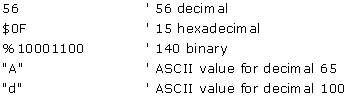
Constants can be equally written in decimal, hexadecimal and binary form. Decimal constants are written without any prefix. Hexadecimal constants start all with a sign $ and binary with %. To make the programming easier, single letters are converted into their ASCII counterparts. The sign constants must be placed into the inverted comas and they contain only one letter as a rule (in adverse case they are string constants).
2.4 Variables
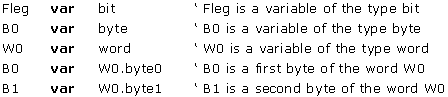
Name_variable var Type_variable
Variables serve for temporary storing of data and results of various arithmetic and logical operations. Variables are stored on the microcontrollers RAM locations, which means that the total number of the variables that can be used depend on the size of RAM.
Accordingly for the 36-byte microcontroller, 22 bytes are reserved for variables.
Variable defining is achieved with the formal word var at the beginning of the program. PIC BASIC supports variables like bit, byte and word. Variable type is selected with reference to the expected value that this same variable can assume in the course of the program run. Therefore the variable of the bit type can take value of 0 or 1, the variable of the byte values from 0 to 256 and finally, word from 0 to 65535.
2.5 Sequences
Name_sequence var type_element [number of the elements]
Sequences of the variables are defined in a similar way as we have done with the variables. "Type_element" represents the value of every element of the sequence, and can be bit, byte or word.
The number of the elements of the sequence is given through value between "[]".Each element of the sequence is accessible by an index. Index starts with zero. When we come to define the number of the elements of the sequence one must always have in mind that the number of locations in RAM memory on which we intend to store variables finite. The next table shows the maximal number of the elements of various types.
|
The size of the sequence |
|
|
Element of the sequence |
Maximal number of elements |
|
BIT | |
|
BYTE | |
|
WORD | |
* Depends on microcontroller
Sequence1 var byte[10] ' the sequence of 10 elements of the type byte
Sequence1 [0] represents the first element of the sequence and sequence1 [9] the last element of the sequence "sequence1".
Sequence2 var byte[8] ' the sequence of 8 elements of the type byte
Sequence2 [0] represents the first element of the sequence and sequence2 [7] the last element of the sequence "sequence2".
2.6 Modifiers
new_name var old_name
By means of modifier it is possible to introduce a new name for the variable already defined. This direction is used relatively rarely but it ought to be mentioned for the sake of completeness. It is used in an identical way as a direction for the definition of the variables. Introduction of a new name is effectuated through the official word var.
![]()
2.7 Symbols
symbol old_name = new_name
Symbols are granted the function exactly the same as direction for modifying variables, i.e. they serve for assigning the new names to the variables and constants. Symbols are introduced for the compatibility of the programs written for Basic Stamp and cannot be used for introducing variables.
![]()
2.8 Direction INCLUDE
INCLUDE "the name of the file"
Direction INCLUDE serves for inserting of a segment of a BASIC file. In this manner is rendered possible to store some general definitions of variables or subroutines that are being executed as parts of several different programs. The effect achieved is the same as if at the location on which is placed the direction INCLUDE simultaneously copied the contents of whole file.
2.9 Comments
' .... Comment.... '
In the course of program writing there's a space for lot of comments even if it may be self-evident what is the main purpose of the program. Although it may well seem as a shear waste of time, it may play later a crucial role (comments don't occupy an additional memory space in the memory of a microcontroller). Comments should give useful instructions about all that the program is doing. Comment as Set Pin0 to 1 simply explains the syntax of the language but fails to pinpoint the purpose of the act. Something of a sort Turn the Relay on may prove itself to be much more useful.
At the beginning of the program it should be described what is the program used for, who were the authors and when was it written. Stipulating the information concerning revision and the exact date may be useful too. Even every concrete statement about connection to each pin can be crucial in an effort to memorize the very hardware for which this program was designed to operate.
2.10 Programming line with more instructions
Compactness and better visuality of a program can be achieved by logically grouping instructions by using ":". In that way the block of instructions can be placed all in a single line, while instruction remain mutually separated with ":".
B2 = B0
B0 = B1
B1 = B2
The three upper instructions can be written in a single row as:
B2 = B0 : B0 = B1 : B1 = B2
2.11 Transfer of a instruction into another line
In case that instruction has big number of parameters so that they cannot stay all into another programming line, there is a possibility that the intake of parameters continue in the next row what is done by means of "_" at the end of line. The typical examples are the instructions lookup, branch and sound.
lookup KeyPress,["1","4","7","*","2","5","8","0","3","6","9","#","N"]
2.12 Define
DEFINE the value parameter
Instructions of the PIC BASIC language can have some parameters from which depends the exact way the instructions are executed. Those parameters assume some predefined values that appear in the most of the cases. A frequency of an oscillator is a good example for that. If not otherwise stated the tact of the oscillator is taken by default as 4MHz. In case that the used oscillator is of a different frequency from 4MHz it is necessary using the DEFINE direction to specify that frequency and communicate it to all the programs that contain within instructions depending on the tact of the microcontroller. One such instruction is for the serial transfer. In case that the instruction DEFINE is omitted and in gear is 8Mhz instead of 4Mhz oscillator, all the instructions that depend on the tact of microcontroller will be executed 2 times quicker. For instance, if the parameter of the speed of transfer amounts to 9600 bauds by using SERIN instruction, the data transfer would be effectuated at the speed 19200. In the same way the instruction pause 1000 the delay realized would be 0.5s instead 1.0s. It is also possible similarly to upgrade the resolution of the instructions. What is next is the review of the usage for DEFINE direction in case of adjusting of parameters explained within each particular instruction.
|
The use of a direction DEFINE |
||
|
parameter |
description |
instruction on which it acts |
|
I2C_HOLD 1 |
pause 12C transfer while the tact is on a low level |
I2COUT, I2COUT |
|
I2C_INTERNAL 1 |
internal EEPROM in series 16Cexxx and 12Cxxx of the PIC microcontroller |
I2COUT, I2COUT |
|
I2C_SCLOUT 1 |
serial tact is a bipolar at the place of an open collector |
I2CWRITE, I2CREAD |
|
I2C_SLOW 1 |
for the tact > BMHz OSC with the devices of a standard velocity |
I2CWRITE, I2CREAD |
|
LCD_DREG PORTD |
LCD data port |
LCDOUT, LCDIN |
|
LCD_DBIT 0 |
Initial bit of a data 0 or 4 |
LCDOUT, LCDIN |
|
LCD_RSREG PORTD |
RS (Register select) port |
LCDOUT, LCDIN |
|
LCD_RSBIT 4 |
RS (Register select) pin |
LCDOUT, LCDIN |
|
LCD_EREG PORTD |
enable port |
LCDOUT, LCDIN |
|
LCD_EBIT 3 |
enable bit |
LCDOUT, LCDIN |
|
LCD_RWREG PORTD |
read/write port |
LCDOUT, LCDIN |
|
LCD_RWBIT 2 |
read/write bit |
LCDOUT, LCDIN |
|
LCD_LINES 2 |
No of LCD lines |
LCDOUT, LCDIN |
|
LCD_INSTRUCTIONUS 2000 |
the time of delay of instruction in microseconds (us) |
LCDOUT, LCDIN |
|
LCD_DATAUS 50 |
the time of delay of data in microseconds |
LCDOUT, LCDIN |
|
OSC 4 |
tact of the oscillator in MHz: 3(3.58) 4 8 10 12 16 20 25 32 33 40 |
all instructions of the serial transfer and next pause |
|
OSCCAL_1K 1 |
setting of OSCCAL for PIC12C671/CE673 microcontrollers | |
|
OSCCAL_2K 1 |
the number of data bits | |
|
SER2_BITS 8 |
the slowing of the tact of transfer |
SHIFTOUT, SHIFTIN |
|
SHIFT_PAUSEUS 50 |
instruction LFSR in 18Cxxx microcontrollers |
LFSR |
|
BUTTON_PAUSE 10 |
BUTTON |
|
|
CHAR_PACING 1000 |
SEROUT, SERIN |
|
|
HSER_BAUD 2400 |
HSEROUT, HSERIN |
|
|
HSER_SPBRG 25 |
HSEROUT, HSERIN |
|
|
HSER_RCSTA 90h |
HSEROUT, HSERIN |
|
|
HSRE_TXSTA 20h |
HSEROUT, HSERIN |
|
|
HSER_EVEN 1 |
HSEROUT, HSERIN |
|
|
HSER_ODD 1 |
HSEROUT, HSERIN |
|
Example:
Slike i primeri
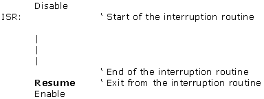
2.13 DISABLE
DISABLE
Before entering the interrupt routine, it is necessary to switch off the interrupts in order to avoid any new interruption in the course of data processing. The interruptions are forbidden in a manner that the instruction "DISABLE" reset the bit GIE in the register INTCON.
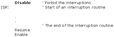
2.14 ENABLE
ENABLE
In the course of execution of the interruption routine, the interrupts must be forbidden by resetting the bit GIE in the INTCON register. When the interruption processing is finished, the interruptions must be allowed once again with the instruction "ENABLE".
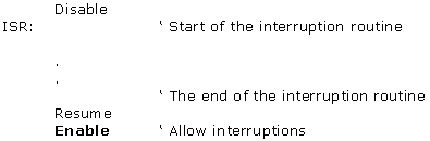
2.15 ON INTERRUPT
On interrupt LABEL
With instruction "On interrupt" is indicated the label on which the program will "jump" when the interruption happened, i.e. from which label the interruption routine starts.
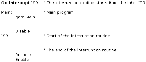
2.16 RESUME
RESUME
Return from the interruption routine to the main program.
Chapter 3
OPERATORS
Introduction
3.1 Expressions 3.2 Instructions 3.3 Arithmetical operators
3.3.1 Multiplication 3.3.2 Division 3.3.3 Shift 3.3.4 ABS 3.3.5 COS 3.3.7 DIG 3.3.8 MAX and MIN 3.3.9 NCD 3.3.10 REV 3.3.11 SIN 3.3.12 SQR
3.4 Bit operators 3.5 The operators of comparison 3.6 Logical operators
Introduction
The PIC BASIC language possesses the operator set used to assign the values, compare objects and perform multitude of other operations. The objects manipulated for that purposes are called operands (which themselves can be variables or constants). The operators of PIC BASIC language must have at least two operands. They serve to create instructions and expressions that together with variables, constants and comments in effect compose the program.
3.1 Expressions
Combinations of operators and operands are called expressions. The expression does the computation and furnishes the result or starts some other activity.
|
' The expression that sums up the values of the
variables B and C and |
In application of any expression the attention must be paid that the result of the computation must be within the range of variable A in order to avoid the overflow and therefore the evident computational error. If the result of expression amounts to 428, and the variable A is of BYTE type having range between 0 and 255, the result accordingly obtained will be 172 - obviously the wrong one.
3.2 Instructions
Each instruction determines an action to be performed. As a rule, the instructions are being executed in an exact order in which they are written in the program. However, the order of their execution can be changed as well employing the instructions for the change of the flow of a program to another segment of the program such as the instructions of the ramification, jump or interrupt.
|
' if A = 23 jump to label Minute |
Instruction IF...THEN contains the conducting expression Time=60 composed in its own rights of two operands, the variable Time, constant 60 and the operator of comparison (=). The instructions of PIC BASIC language can be distinguished as the instructions of choice (decision making) repeating (loops), jump and specific instruction for an access to the peripheries of the microcontrollers. Each of these instructions is explained in detail in Chapter 4.
Operators are numerous, but
for almost 90% of all the programs it is necessary to know only few of them. It
suffices to look how many operators are used in the examples in Chapter 5, 6
and 7.
After the activities they perform, the operators can be classified into the following categories:
- Arithmetic
operators
- Bit operators?
- The operators of comparison
- Logical operators
3.3 Arithmetic operators
All arithmetic operators work in 16-bit precision with the unsigned values what means that the range of the operand is from 0 to 65535. In order to group operations, one may use brackets.
A = (B + C) * (D - E)
In the following table all the supported arithmetic operators are listed.
|
Operator Description |
|||
|
Operator |
Description |
Operator |
Description |
|
summation |
ABS |
absolute value of a number |
|
|
subtraction |
COS |
cosine of an angle |
|
|
multiplication |
DCD |
bit decoding |
|
|
the result is in higher 16 bits |
DIG |
value of the digit for a decimal number |
|
|
the result is in middle 16 bits |
MAX |
maximum of a number |
|
|
division |
MIN |
minimum of a number |
|
|
remainder |
NCD |
priority coding |
|
|
<< |
left shift |
REV |
bit reversing |
|
>> |
right shift |
SIN |
sine of an angle |
|
assignment of value |
SQR |
square root of a number |
|
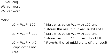
3.3.1 Multiplication
|
Syntax: |
L0
= W1 * 100 |
|
Description: |
PIC BASIC pro does not support directly the work with the 32-bit numbers. It is usual to present a 32-bit variable as a two 16-bit variables. Operator '*' reverts lower 16 bits of a 32-bit result. Operator '**' reverts higher 16 bits of a 32-bit result. These two operators can be used in a combined way for computing 16x16 multiplications in order to produce 32-bit results. |
|
Example: |
|
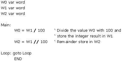
3.3.2 Division
|
Syntax: |
W0
= W1 / 100 |
|
Description: |
As it is the case with multiplication, the operation of division is done over the 16 bit operands. Operator '/' reverts 16-bit integer result while the operator '//' reverts the remainder. |
|
Example: |
|
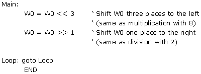
3.3.3 Shift
|
Syntax: |
W0
= W0 << 3 |
|
Description: |
Operators of the shift perform the shift towards left or right from 0 to 15 times. All the new bits that enter from the side have value 0. These two operators belong to the operators over the bits. |
|
Example: |
|
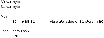
3.3.4 Absolute value of a number
|
Syntax: |
B0 = ABS B1 |
|
Description: |
ABS gives the absolute value of a number. If ABS gets applied to the variable of the BYTE type greater then 127 (set MSB) the result is 256. If the ABS gets applied to the variable of WORD type greater then 32767 (the bit set is of the biggest weight - MSB) result is 65536. |
|
Example: |
|
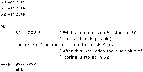
3.3.5 Cosine of an angle
|
Syntax: |
B0 = COS B1 |
|
Description: |
COS reverts the 8-bit value of the cosine. The result is in the second complement (i.e. within the range -127 to 127). For that reason it is necessary to use the lookup table in order to determine the result (cosine of an angle goes in the binary range between 0 and 255 in contrast with usual 0 to 359 degrees). |
|
Example: |
|
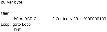
3.3.6 The decoded bit value
|
Syntax: |
B0 = DCD N |
|
Description: |
DCD gives the decoded bit value of the operand whose value is in the range within 0-15. If the operand is 0 then the zeroth bit of the result 1, and if the operand reads as 7, the seventh bit of the result is 1. |
|
Example: |
|
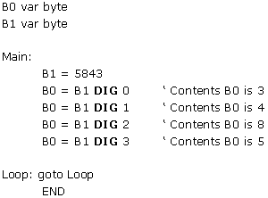
3.3.7 DIG The value of the digit for a decimal number
|
Syntax: |
W = W1 DIG N |
|
Description: |
DIG furnishes the value of the digit of a decimal number. The number whose digits are looked for is 0-3 where 0 is a last right digit i.e. digit of the smallest weight (it is most often used for the work with seven-segment digits for extraction of the digits to be displayed). |
|
Example: |
|
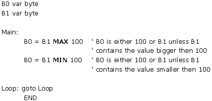
3.3.8 MAX and MIN Maximum and Minimum of a number
|
Syntax: |
B0 = B1 MAX 100 |
|
Description: |
The operator's maximum and minimum are used whenever it is necessary to revert one out of two values that are being compared. If those numbers are for example 100 and 200 operator Max will revert the value 200 and operator Min, value 100. To the difference from the operators "bigger then" and "less then" they revert the entire value and not only the quantification whether some value is smaller or bigger then the other. |
|
Example: |
|
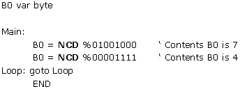
3.3.9 NCD Priority coding
|
Syntax: |
B0
= NCD %01001000 |
|
Description: |
NCD furnishes the value that is coded with the priority code. That gives the position of the first unit, which it encounters from the left side. If the operand is 0 the result is 0 as well. |
|
Example: |
|
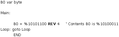
3.3.10 REV Reverting of the lowest bits of the operand
|
Syntax: |
B0 = %10101100 REV 4 |
|
Description: |
REV reverts the order of the lowest bits of the operand. The number of the bits that can be reverted goes from 1 to 16. |
|
Example: |
|
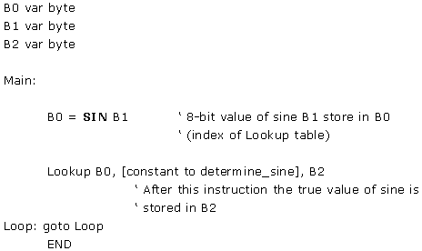
3.3.11 SIN Sine of an angle
|
Syntax: |
B0 = SIN B1 |
|
Description: |
SIN reverts the 8-bit value of the sine. The result is in the second Complement (i.e. within the range -127 to 127). For that reason it is necessary to use the lookup table in order to determine the result (sine of an angle goes in the binary range between 0 and 255 in contrast with usual 0 to 359 degrees). |
|
Example: |
|
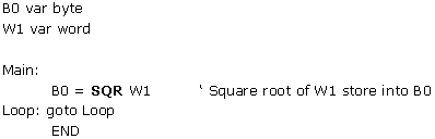
3.3.12 SQR Square root
|
Syntax: |
B0 = SQR W1 |
|
Description: |
SQR reverts a value of a square root. Result is stored into the variable of BYTE type. |
|
Example: |
|
3.4 Bit operators
One of the more important properties of higher programming languages is their capacity to go down to the lower level i.e. the level of the assembler. Bit operators furnish the access to the registers and memory of a microcontrollers at the level of a single bit. Operators supported by the language PIC BASIC are given in the table below:
|
Bit operators |
|
|
Operator |
Description |
|
& |
Logical AND over the bits |
|
Logical OR over the bits |
|
|
Logical XOR over the bits |
|
|
Logical NOT over the bits |
|
|
&/ |
Logical NAND over the bits |
|
Logical NOR over the bits |
|
|
Logical NXOR over the bits |
|
The value result of the expression depends on the fact which of the listed logical operations is executed over the bits of the operand. In that way, it is possible to extract, delete, set or invert the certain bit of the operand.
Example1:
B0 = B0 & %00000001
The upper instruction extracts the value of the lowest bit of the variable B0. When the logical "AND" is performed with the zero, there will be 0 at the position of a corresponding bit (so that all the bits 1-7 will be zeroes). The value will depend on bit 0 in the variable B0 and if it is "0", the value of variable B0 will be "0" and if it is "1" the value of B0 will accordingly be "1".
Example2:
B0 = B0 & %00000100
The upper instruction sets bit2 in the variable B0. When the logical "or" is performed with the unity the result is always equal to "1" regardless of the state of the corresponding bit from B0.
Example 3:
B0 = B0 & %00000010
The upper instruction inverts the bit 1 in variable B0. If the bit was "1" then it turns into "0" and vice versa. The other logical operators are used only rarely so there's no need for their detailed explanation.
3.5 The operators of comparison
The expressions that contain the operators of comparison give after having compared the two operands the result true or false. If the expression of comparison is true then the instruction to be executed is the one on the left side, otherwise the execution of the program continues with the next instruction. The operators of comparison are shown in the table below:
|
Operators of comparison |
|
|
Operator |
Description |
|
= or == |
equal |
|
<> or !=| |
not equal |
|
< |
less then |
|
> |
bigger then |
|
<= |
less then or equal |
|
>= |
bigger then or equal |
These operators are most often used in examination of the conditions by the instructions such as IF...THEN.
Example:
If Seconds = 60 then
minutes = minutes + 1
Seconds = Seconds + 1
If the variable " Seconds" equals 60 the condition of the comparison is true and the instruction "Minutes=Minutes+1" will be executed then. Unless the expression is not true the instruction "Seconds=Seconds+1" will be executed instead.
3.6 Logical operators
Logical operators serve for the operations over the variables, which take two possible values 0 or 1. These values may well be interpreted as "condition is fulfilled" what corresponds to state "1" and "condition is not fulfilled" which corresponds to the state "0". They are used in the very same way as the operators of comparison within the frame of the instruction IF...THEN. The list of the logical operators is shown in the table below.
|
Logical operators |
|
|
Operator |
Description |
|
AND or && |
Logical AND |
|
OR or || |
Logical OR |
|
XOR or ^^ |
Logical XOR |
|
NOT |
Logical NOT |
|
NOT AND |
Logical NAND |
|
NOT OR |
Logical NOR |
|
NOT XOR |
Logical NXOR |
Example1:
If A Or B THEN GOTO Lab
If the condition is fulfilled, i.e. if at least one of the operands A or B equal to one, then the program jumps to the label Lab.
Example2:
IF (Seconds>59) And (Minutes>59) THEN Hours=Hours+1
The conditions may be complex as well. Separating into the brackets is obligatory otherwise the result can be very unpredictable.
Chapter 5
SAMPLE PROGRAMS FOR SUBSYSTEMS WITHIN THE MICROCONTROLLER
Introduction
5.1 Using the interrupt mechanism 5.2 Using the internal AD converter 5.3 Using the TMR0 timer 5.4 Using the TMR1 timer 5.5 Using the PWM subsystem 5.6 Using the hardware UART subsystem (RS-232 communication)
Introduction
Every microcontroller is supplied with at least a few integrated subsystems - commonly, these include timers, interrupt mechanisms and AD converters. More powerful microcontrollers can command greater number of built-in subsystems. Some of frequently encountered systems are detailed in this chapter.
5.1 Using the interrupt mechanism
Interrupts are mechanisms which enable instant microcontroller response to events such as : TMR0 counter overflow, state changes on RB0/INT pin, data is received over serial communication, etc. With bigger microcontrollers, number of interrupt sources is even greater. In normal mode, microcontroller executes the main program as long as there are no occurrences that would cause interrupt. When interrupt does take place microcontroller stops the execution of the main program and starts executing part of the program (interrupt routine) that will analyze and handle the interrupt. Analysis in necessary because PIC microcontrollers call the same interrupt routine in response to any of the mentioned events. Therefore, the first task is to determine which event caused the interrupt. After the analysis comes the interrupt handling, which is executing the appropriate part of program code tied to a certain event.
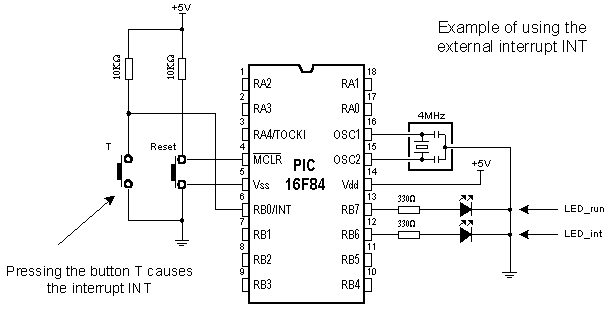
Button T is connected to the external interrupt input INT (pin RB0/INT) so that pressing the button is considered an interrupt occurrence. In order to see the change caused by interrupt LED diodes are connected to the pins RB6 and RB7. LED_run diode signalizes that the main program is being executed, while LED_ini diode signalizes the interrupt caused by pressing the button T. Following instructions are used in PIC BASIC programs which contain interrupt routine :
On Interrupt goto Address Defines the interrupt vector (address of interrupt routine)
Disable Disables the interrupts
Enable Enables the interrupts
Resume Return to the main program after handling the event
Following example demonstrates usage of external interrupt INT located on pin RB0. At the same time, program gives an example how to handle multiple interrupt sources.
Program which handles interrupt must have the main loop (program) and an interrupt routine. Program in the main loop keeps LED_run diode on and LED_int diode off. Pressing the button T causes the interrupt and the microcontroller will stop executing the main program and start executing the interrupt routine ISR marked by On interrupt instruction.
At the beginning of the interrupt routine there is instruction Disable. This instruction disables all interrupts until handling the current interrupt is over. ISR routine then analyses the interrupt by checking bits (flags) set on "1" with couple of if...then instructions, because there are several possible interrupt causes. In our case, an external interrupt took place (pin RB0/INT state changes) and therefore bit INTF in INTCON register is set and the microcontroller continues program execution from the label INTF. Part of the program code following the label INTF handles the interrupt and resets INTF bit in order to enable interrupts again. In this case, handling the external INT interrupt changes state of diodes LED_int and LED_run : it turns off LED_run and turns on LED_int for half second period. After INTF is being reset, microcontroller continues executing the program from Exit_ISR label where interrupts are enabled (instruction Enable) and microcontroller returns to executing the main program (instruction Resume).
Why use interrupts at all ? In situations where the microcontroller must respond to events unrelated to the main program it is very useful to have an interrupt. Perhaps, one of the best examples is multiplexing the seven-segment display. If multiplexing code is part of the interrupt routine tied to timer interrupt the main program will be much less burdened because display refreshing will work in the background of the main program.

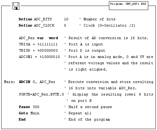
5.2 Using the internal AD converter
Certain microcontrollers have built in analog-digital converter (abbrev. ADC). Usually, these AD converters do not exceed 8 to 10 bits resolution allowing them voltage sensitivity of 19.5mV with 8-bit resolution and 4.8mV with 10-bit resolution (assuming that default 5V voltage is used).
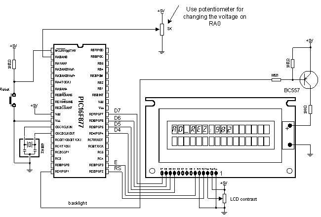
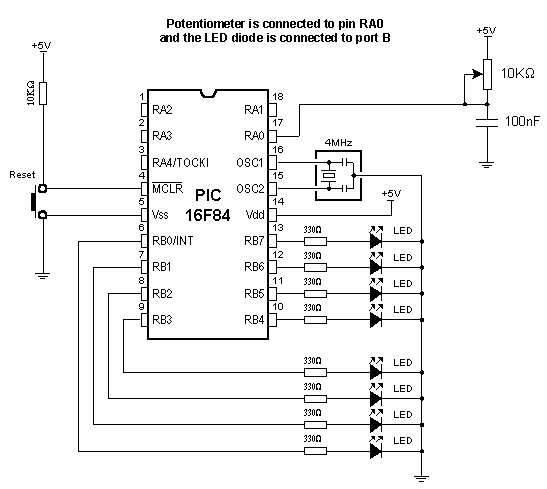
The simplest AD conversion program would use 8-bit resolution and 5V of microcontroller power as referent voltage (value which the value "read" from the microcontroller pin is compared to). In the following example we measure voltage on RA0 pin which is connected to the potentiometer (picture below).
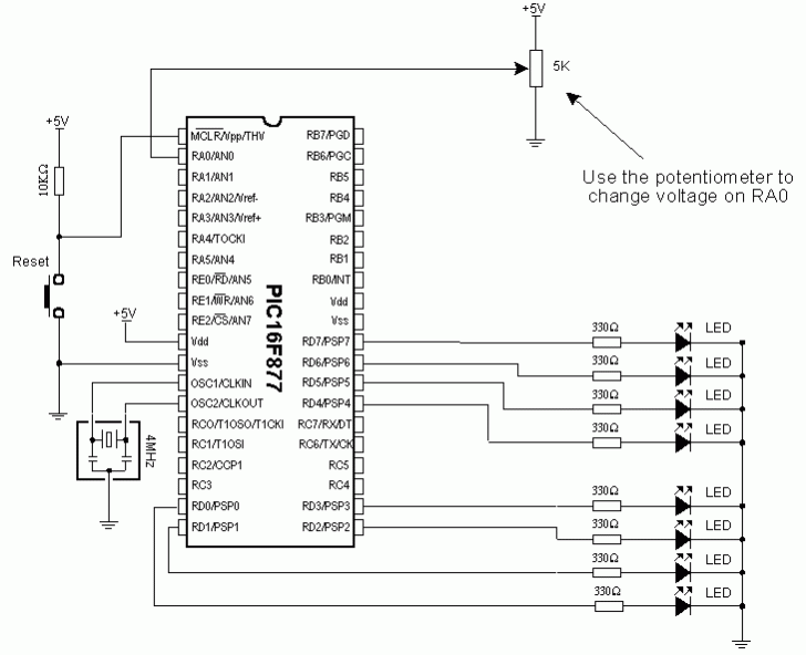
Potentiometer gives 0V in one terminal position and 5V in the other, so that digitalized voltage can take values ranging from 0 to 256 due to the fact that 8-bit conversion is used. The following program reads voltage on RA0 pin and displays it on port B diodes. If not one diode is on, result is zero and if all of diodes are on, result is 255.
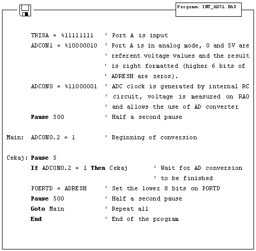
At the very beginning, it is necessary to properly initialize 2 bit registers ADCON1 and ADCON0. Afterwards, only thing required is to set ADCON0.2 bit which initializes the conversion and checks ADCON0.2 to determine if conversion is over. After the conversion is over, result is stored into ADRESH and ADRESL where from it can be copied. Former example can also be carried out via ADCIN instruction. Following example uses 10-bit resolution and ADCIN instruction.
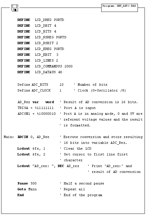
As one port is insufficient, LCD can be used for displaying all of the 10 bits of result. Connection scheme is on the picture below and appropriate program follows.
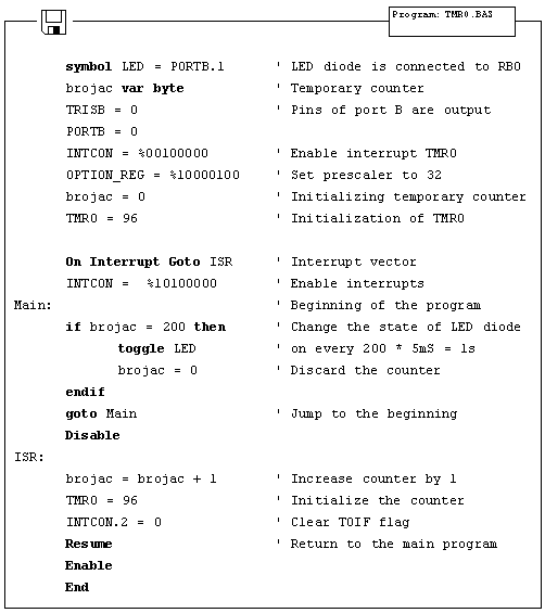
5.3 Using the TMR0 timer
TMR0 timer is 8-bit and has working range of 255. Assuming that 4MHz oscillator is used, time period TMR0 can measure falls into 0-256 microseconds range (with 4MHz frequency TMR0 increments by one microsecond). If prescaler is used that period can be prolonged, because prescaler divides the clock in a certain ratio (prescaler settings are made in OPTION_REG register).
Following program illustrates use of TMR0 timer for generating 1 second time period. Prescaler is set to 32, so that internal clock is divided by 32 and TMR0 increments every 31 microseconds. If TMR0 is initialized on 96, overflow occurs in (256-96)*31 us = 5 ms. If variable "Brojac" is increased every time interrupt takes place, we can measure time according to the value of variable "Brojac". If "Brojac" is set to 200, time will total 200*5 ms = 1 second.
Before the main program, TMR0 should have interrupt enabled (bit 2) and GIE bit (bit 7) in INTCON register should be set.
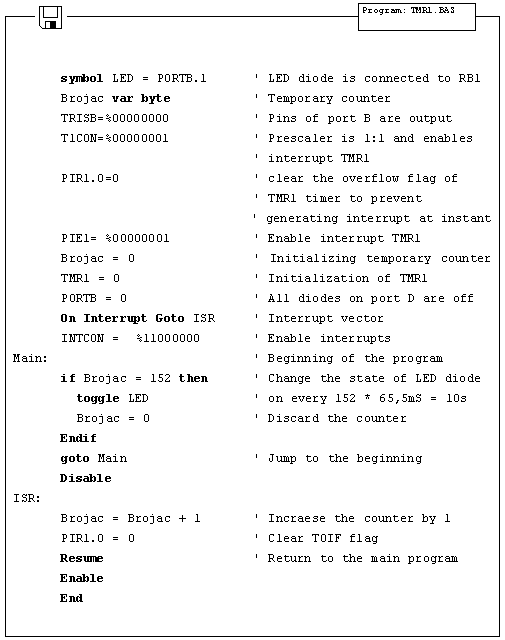
5.4 Using the TMR1 timer
Unlike TMR0, TMR1 is 16-bit and has working range of 65536. Assuming that 4MHz oscillator is used, time period TMR1 can measure falls into 0-65536 microseconds range (with 4MHz frequency TMR01 increments by one microsecond). If prescaler is used that period can be prolonged, because prescaler divides the clock in a certain ratio (prescaler settings are made in T1CON register).
Before the main program, TMR1 should be enabled by setting the zero bit in T1CON register. Besides that, first bit of the register should be set to zero, thus defining the internal clock for TMR1.
Besides T1CON, other important registers for working with TMR1 include PIR1 and PIE1. The first contains overflow flag (zero bit) and the other is used to enable TMR1 interrupt (zero bit).
When TMR1 interrupt is enabled and its flag reset only thing left to do is to enable global interrupts (bit 7) and peripheral interrupts (bit 6) in the INTCON register.
The following program illustrates use of TMR1 register for generating 10 seconds time period. Prescaler is set to 00 so there is no dividing the internal clock and overflow occurs every 65.536 ms. If variable "Brojac" is increased every time interrupt takes place, we can measure one minute period according to the variable "Brojac". If "Brojac" is set to 152, time will total 152*65.536 ms = 9.960 second.
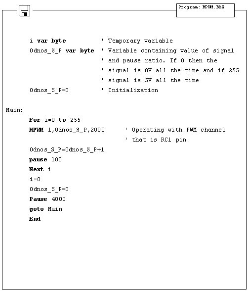
5.5 Using the PWM subsystem
Microcontrollers of PIC16F87X series have one or two PWM outputs built-in (those in 40-pin casing have 2, while those in 28-pin casing have 1). PWM outputs are located on RC1 and RC2 pins in case of 40-pin microcontrollers and on RC2 pin in case of 28-pin microcontrollers. HPWM instruction greatly simplifies using the PWM. There are only 3 parameters to be set :
PWM Channel : defines which PWM channel is used; "1" defines channel on RC1 pin, while "2"
defines channel on RC2 pin.
Ratio_S_P : defines the ratio of on and off signals on pin. "0" defines continual
off state, whereas "255" defines continual on state. All values within these
limits define appropriate ratio of on and off signals on pin. (i.e. "127" gives
50% of 0V on output and 50% of 5V on output).
Frequency : defines PWM signal frequency. Top frequency for any oscillator is 32767Hz.
The following example demonstrates use of PWM for getting various light intensities on LED diode connected to RC1 pin (PWM channel 0). Parameter defining ratio of on and off signals is continually increased in the for-next loop and takes value from 0 to 255, resulting in continual intensifying of light on LED diode. After value of 255 has been reached, process begins anew.
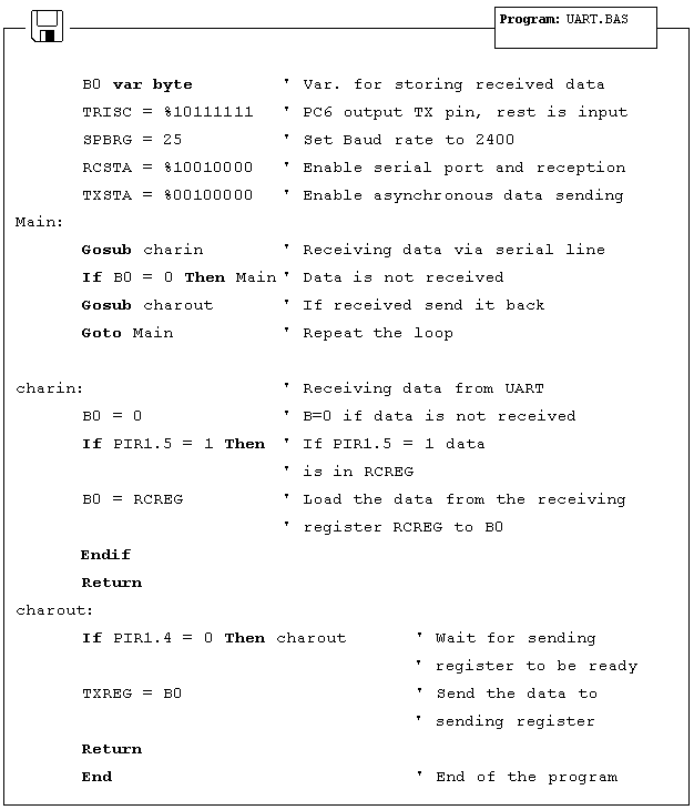
5.6 Using the hardware UART subsystem (RS-232 communication)
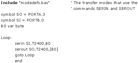
Easiest way to transfer data between microcontroller and some other device (i.e. PC or other microcontroller) is the RS-232 communication. It is serial asynchronous 2-line (Tx for transmitting and Rx for receiving) data transfer for within 10m range.
This example shows data transfer between the microcontroller and PC connected by RS-232 line interface (MAX232) which has role of adjusting signal levels on the microcontroller side (it converts RS-232 voltage levels +/- 10V to TTL levels 0-5V and vice versa). Microcontroller can achieve communication with serial RS-232 line via hardware UART (Universal Asynchronous Receiver Transmitter) which is the integral part of PIC16F87X microcontrollers.
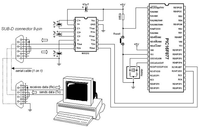
UART contains special registers for receiving and transmitting data as well as BAUD RATE generator for determining data transfer rate.
The program below illustrates use of hardware serial communication subsystem (serial communication can also be software based on any of 2 microcontroller pins). Data received from PC is stored into variable B0 and sent back to PC as confirmation of successful transfer. Thus, it is easy to check if communications works properly. Transfer format is 8N1 and transfer rate is 2400 baud.
In order to achieve communication, PC must have the communication software. One such program is part of the MicroCode studio. It can be accessed by clicking View and then Serial Communication Window. New window will appear on screen and can be used for adjusting transfer settings. First it is necessary to set transfer rate by clicking Baudrate on the left of the window (set it to 2400, because microcontroller is set to that rate). Communication port is selected by clicking one of the 4 available depending on port connected to a serial cable.
After making adjustments, clicking Connect starts the communication. Type your message and click Send Message - message is sent to the microcontroller and back, where it is displayed on the screen.
Chapter 6
SAMPLES WITH PIC16F84 MICROCONTROLLER
Introduction
6.1 LED diode 6.2 Button 6.3 Generating sound 6.4 Potentiometer 6.5 Seven-segment displays 6.6 Step motor 6.7 Input shift register 6.8 Output shift register 6.9 Software serial communication 6.10 Building light control
Introduction
This chapter gives detailed examples of connecting PIC16F84 microcontroller to peripheral components and appropriate programs written in BASIC. All of the examples contain electrical connection scheme and program with comments and clarifications. You have the permission to directly copy these examples from the book or download them from the web site www.mikroelektronika.co.yu
6.1 LED diode
One of the most frequently used components in electronics is surely the LED diode (LED stands for Light Emitting Diode). Some of common LED diode features include : size, shape, color, working voltage (Diode voltage) Ud and electric current Id LED diode can have round, rectangular or triangular shape, although manufacturers of these components can produce any needed shape by order. Size i.e. diameter of round LED diodes ranges from 3 to 12 mm, with 3 or 5 mm sizes most commonly used. Color of emitting light can be red, yellow, green, orange, blue, etc. Working voltage i.e. necessary for LED diode to emit light is 1.7V for red, 2.1V for green and 2.3 for orange color. This voltage can be higher depending on the manufacturer. Normal current Id through diode is 10 mA, while maximal current reaches 25 mA. High current consumption can present problem to devices with battery power supply, so in that case low current LED diode (Id ~ 1-2 mA) should be used. For LED diode to emit light with maximum capacity, it is necessary to connect it properly or it might get damaged.
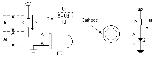
The positive pole is
connected to anode, while ground is connected to cathode. For matter of
differentiating the two, cathode is marked by mark on casing and shorter pin.
Diode will emit light only if current flows from anode to cathode; in the other
case there will be no current. Resistor is added serial to LED diode, limiting the maximal current
through diode and protecting it from damage. Resistor value can be calculated
from the equation on the picture above, where
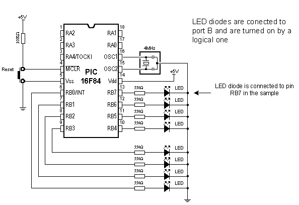
LED diode can be connected to microcontroller in two ways. One way is to have microcontroller "turning on" LED diode with logical one and the other way is with logical zero. The first way is not so frequent (which doesn't mean it doesn't have applications) because it requires the microcontroller to be diode current source. The second way works with higher current LED diodes.
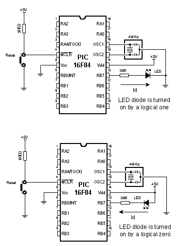
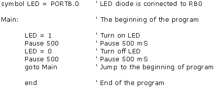
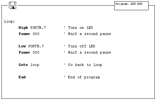
The following example uses instructions High, Low and Pause to turn on and off LED diode connected to seventh bit of port B every half second.
6.2 Button
Button is a mechanical component which connects or disconnects two points A and B over its contacts. By function, button contacts can be normally open or normally closed.
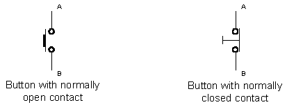
Pressing the button with normally open contact connects the points A and B, while pressing the button with normally closed contact disconnects A and B.
Buttons can be connected to the microcontroller in one of two ways:
In the first case, button is connected in a way that logical one (+5V) remains on microcontroller input pin while button is not pressed. Resistor between a button and power voltage has role of holding the input pin in defined state when the button is not pressed (in this case a logical one). This is necessary as a protection from glitch on input pin that might cause misinterpretation of program, i.e. as if button is pressed when it is not.
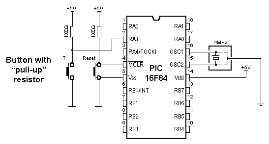
When the button is pressed, input pin is short circuited to the ground (0V) which indicates change on input pin. Voltage has dropped from 5V to 0V. This change is interpreted by program as if button was pressed and part of program code tied to a button (for example turn on LED diode) is then executed. This way of defining pin states is called defining with "pull-up" resistors, associating that the line is held up on the logical one level.
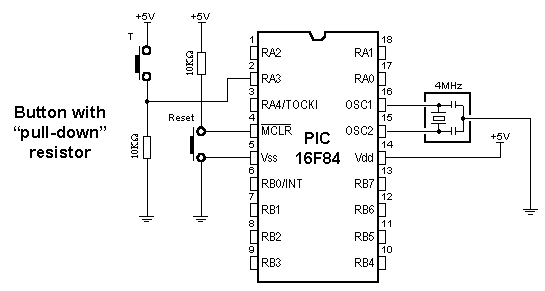
In the other case, button is connected in a way that logical zero remains on input pin. Now, resistor is between input pin and a logical zero, meaning that pressing the button brings logical one to input pin. Voltage goes up from 0V to +5V. Microcontroller program should recognize change on input pin and execute the specific part of program code. This way of defining pin states is called defining with "pull-down" resistors, associating that the line is held down on the logical zero level.
Common way to connect the button is with pull-up resistors, meaning that pressing the button changes pin state from logical one to logical zero. Following picture displays four button connected to the microcontroller using the pull-up resistors.
Problem that occurs when working with buttons is contact debounce in the moment when button is pressed. Debounce is consequence of the contact and heavily depends on the very button.
One of the ways to solve the contact debounce problem is given in the following part of program code :
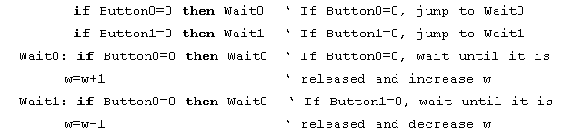
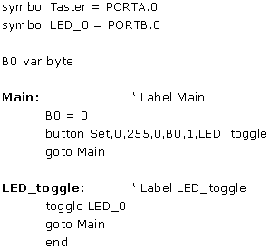
Pressing the Button0 causes the program to jump to address Wait0 where it remains in the loop until the button is released (this achieves that single button push is just once handled in program). When Button0 is released program continues executing instructions (in this case variable W is increased by one). Pressing Button1 causes the same effect, except that variable W is decreased by one.
Problem might arise if an interrupt or some other source slows down the program execution, so that program finds itself on Wait0 or Wait1 lines after the button is released. This might cause program blocking until button is pressed again.
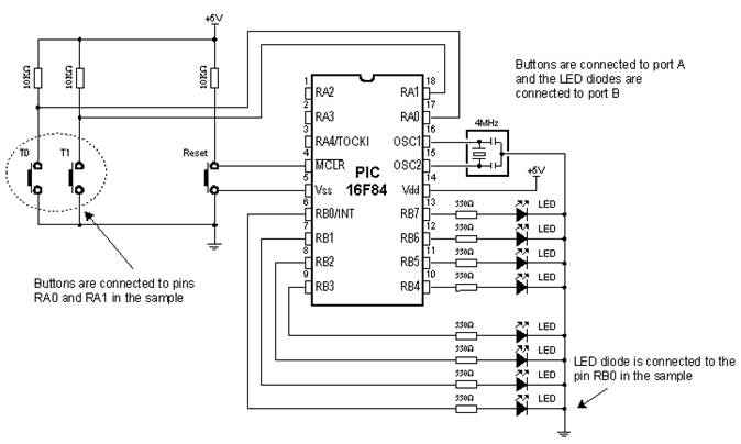
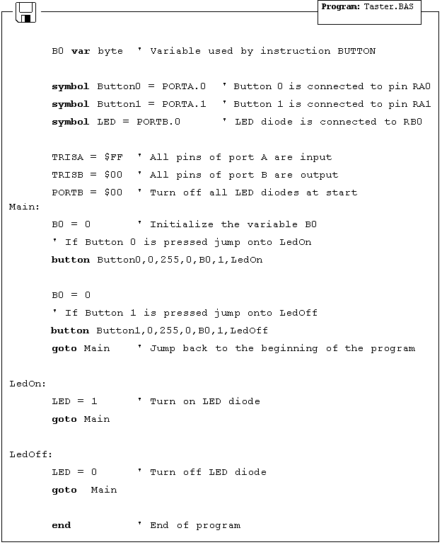
In the following program for reading the button states, BASIC instruction Button is used which eliminates the contact debounce.
The program reads buttons T0 and T1 which are connected to the pins RA0 and RA1, respectively. Pressing the button 0 executes part of program code which turns on LED diode on pin RB0. Pressing the button 1 executes part of program code which turns off LED diode on the same pin. The mentioned instruction is among the most complex instructions of BASIC program language. Besides few arguments that should be defined, instruction has an argument for setting the delay time between recognition of two different button pressures (the third argument). Its setting depends on the purpose of the button as well as mechanical properties of the button. Still, it came clear over time that maximal value of last argument represents the best solution for most applications, because of great disproportion in human reaction and microcontroller speed.
6.3 Generating sound
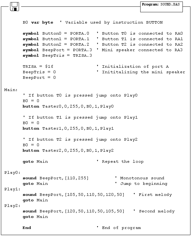
Sometimes it is necessary to provide sound signalization on device, besides the visual one (LED diodes). The following example shows one way to generate sound signal using the mini speaker and BASIC instruction Sound.
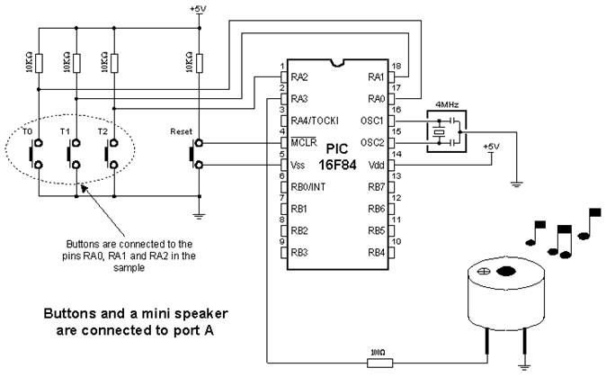
Buttons are connected to pins RA0, RA1 and RA2. Pressing any of these executes part of the code for generating impulse sequence on RA3 pin, which can be heard as one monotonous sound or a melody on mini speaker. Consecutive execution of instruction Sound with different parameters allows composing various melodies.
In the following program, pressing the button T0 generates one monotonous sound on a mini speaker, while pressing the buttons T1 and T2 executes sequences of Sound instructions which can be heard as two different melodies on a mini speaker.
6.4 Potentiometer
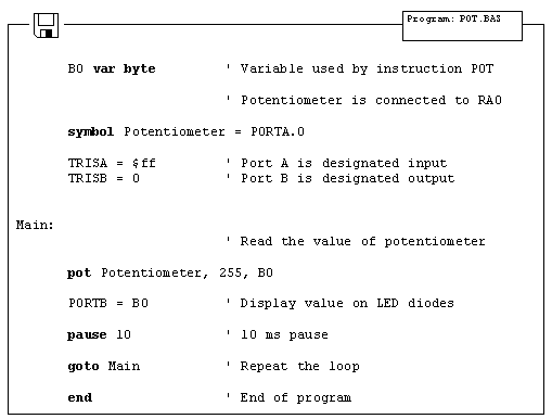
In order to measure and display analog values, besides the microcontroller, it is necessary to have an AD converter. This can be an expensive solution if some less precise measuring is required, for example potentiometer voltage. For this reason PIC BASIC features the POT instruction for using the microcontroller without AD converter.
RC pair which consists of potentiometer (typical resistance in 5-50k range) and a 100nF capacitor is connected to RA0 pin. Reading the potentiometer is based upon measuring the time period between capacitor discharging and charging. Measuring scale ranges from 0 to 255 as if 8-bit AD converter was used.
The following program reads potentiometer value in 0-255 range and displays it on LED diodes connected to the port B.
6.5 Seven-segment displays
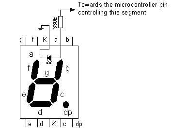
Most common form of communication between the microcontroller system and a man is, of course, the visual communication. The simplest form is the LED diode, while seven-segment digits represent more advanced form of visual communication. The name comes from the seven diodes (there is an eighth diode for a dot) arranged to form decimal digits from 0 to 9. Appearance of a seven-segment digit is given on a picture below.
As seven-segment digits have better temperature features as well as visibility than LCD displays, they are very common in industrial applications. Their use satisfies all criteria including the financial one. Simple application would be displaying value read from a certain sensor.

One of the ways to connect seven-segment display to the microcontroller is given on a picture above. System is connected to use seven-segment digits with common cathode. This means that segments emit light when logical one is brought to them, and that output of all segments must be a transistor connected to common cathode, as shown on the picture. If transistor is in conducting mode any segment with logical one will emit light, and if not no segment will emit light, regardless of its pin state.
If we use the scheme from the picture above, one of the ways to realize the display in BASIC could be the following program code :

Variables LEDDisp1
and LEDDisp2 are actually pins 1 and 0 of port A, which bases of transistors T1
and T2 are connected to. Setting logical one on those pins turns on the
transistor, allowing every segment from "a" to "h", with
logical one on it, to emit light. If there is logical zero on transistor base,
none of the segments will emit light, regardless of the pin state. Tens digit
is disabled at the very beginning of program, ahead of label
Purpose of the program is to display figures from 0 to 9 on the ones digit, with 0.5 seconds pause in between. In order to display any number, it's mask must be sent to port B. For example, if we need to display "1", segments "b" and "c" must be set to 1 and the rest must be zero. If (according to the scheme above) segments b and c are connected to the first and the second pin of port B, values 0000 and 0110 should be set to port B. These values which are set to port are commonly called "masks". Mask for number "1" is value 0000 0110 or $06 (hexadecimal). The following table contains corresponding mask values for numbers 0-9 :
|
Digit |
Seg. h |
Seg. g |
Seg. f |
Seg. e |
Seg. d |
Seg. c |
Seg. b |
Seg. a |
HEX |
|
$3F |
|||||||||
|
$5B |
|||||||||
|
$4F |
|||||||||
|
$6D |
|||||||||
|
$7D |
|||||||||
|
$7F |
|||||||||
|
$6F |
Program uses the instruction Lookup to apply an appropriate mask to numerical value. Instruction Lookup works very simply - it puts a character from a sequence, its position defined by numerical value Digit, to variable Mask. For example, Mask will take value $5B if Digit has value 2. In that manner, we can easily get mask for any decimal digit.
Continual display of Mask (PORTB=Mask) for appropriate value of variable Digit, with 0.5sec pause, will produce an effect of digits rotating from 0 to 9.
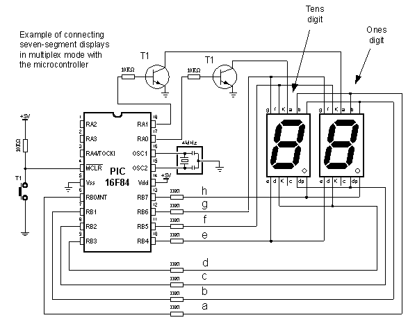
Problem with multiplexing occurs when displaying more than one digit is needed on two or more displays. It is necessary to put one mask on one digit quickly enough and activate it's transistor, then put the second mask and activate the second transistor (of course, if one of the transistors is in conducting mode, the other should not work because both digits will display the same value).
New program differs from the one above in converting 2-digits value to 2 masks, which are displayed in a way that human eye gets impression of simultaneous existence of both figures (this is the reason for calling it "multiplexing" - only one display actually emits in any given moment).
Let's say we need to display number 35. First, the number should be separated into tens and ones (in this case, digits 3 and 5) and their masks sent to port B. This separation can be done with instruction Dig. For example, Digit1= W dig 0 will extract ones digit from variable W and store it into variable Digit1. If 0 is substituted with 1, tens digit will be extracted. Following the same logic, 2 extracts number of hundreds, 3 number of thousands, etc.
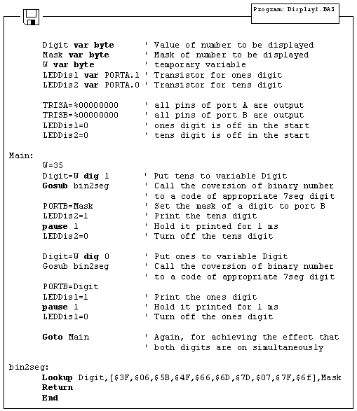
This part of program code prints value 35 on two seven-segment displays. The rest of the program is very similar to the last example, except for having one transition caused by displaying one digit after another. This transition can be spotted when LEDDisp1 is being turned off and LEDDisp2 turned on with a new mask. Lookup table is still the same and may be called as a subroutine when needed.
The multiplexing problem is solved for now, but the program doesn't have a sole purpose to print values on displays. It is commonly just a subroutine for displaying certain information. However, this kind of solution for printing data on display will make essence of the program much more complicated. This newly encountered problem may be solved by moving part of the program for refreshing the digits (part of the program code for handling the masks and controlling the transistors) to interrupt routine. The following program shows how to use interrupt for refreshing the display. Main program increases the value of variable W from 0 to 99 and that value is printed on displays. After reaching the value of 99, counter begins anew.
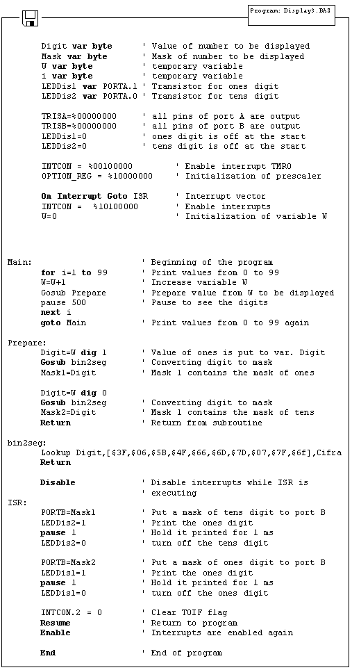
Interrupt initialized in this way will generate interrupt every time TMR0 timer changes state from 255 to 0. Every time interrupt takes place, interrupt routine will be executed so that human eye gets impression that both displays print values simultaneously. As can be seen from the program code, everything tied to displaying digits is moved to interrupt routine. However, part of the code for forming the masks to be displayed is in the special subroutine (Gosub Prepare) in order to make interrupt routine code as short as possible. Another reason for this kind of organization is also the need to create masks only when variable W is changed and not every time interrupt takes place.
In the course of main program, programmer doesn't have to take care of refreshing the display nor anything about displays whatsoever. It is only necessary to call subroutine "Preparation" every time value that will be displayed changes.
As 2-digit values don't satisfy most needs, the following step is adding two additional digits. Program for realization of 4 seven-segment displays is just an expansion of the program above. The main difference is in the part for separating values to ones, tens, hundreds and thousands.
6.6 Step motor
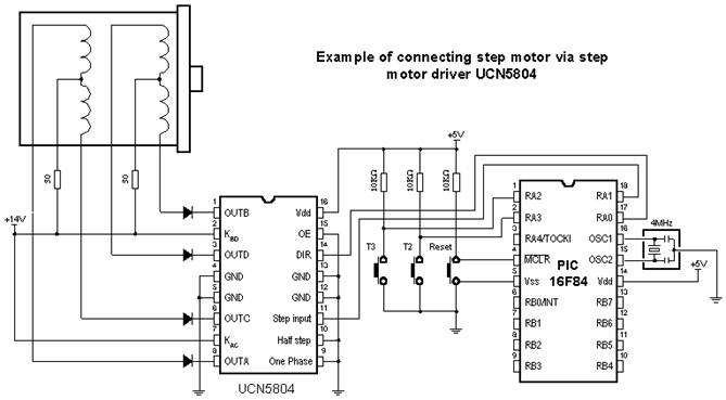
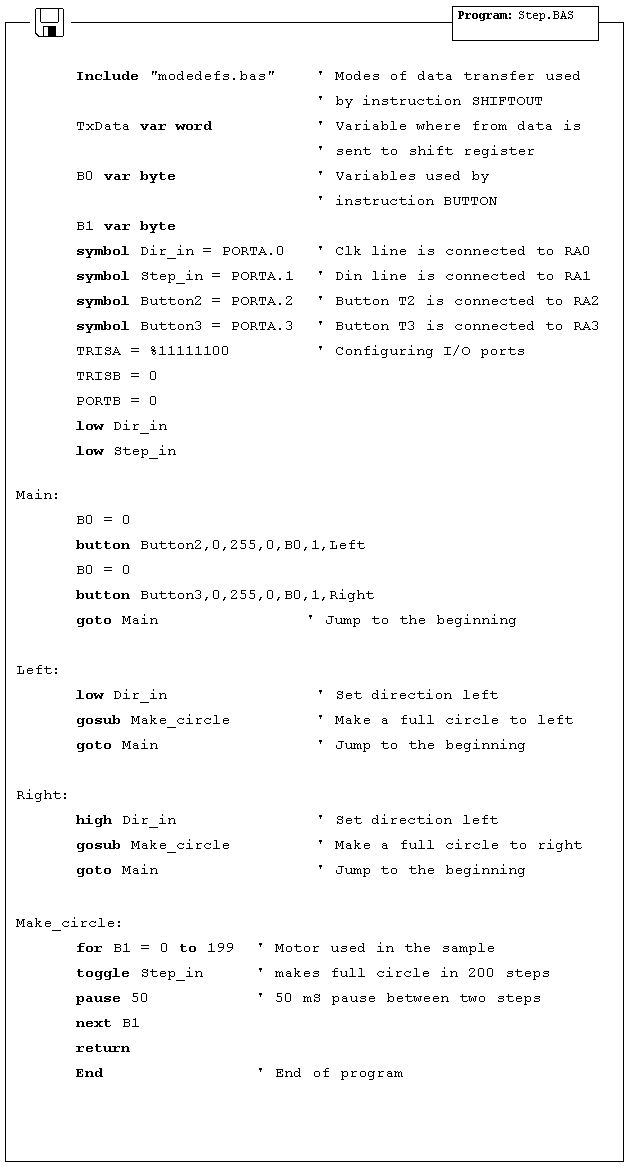
Of all motors, step motor is the easiest to control. It's handling simplicity is really hard to deny - all there is to do is to bring the sequence of rectangle impulses to one input of step controller and direction information to another input. Direction information is very simple and comes down to "left" for logical one on that pin and "right" for logical zero. Motor control is also very simple - every impulse makes the motor operating for one step and if there is no impulse the motor won't start. Pause between impulses can be shorter or longer and it defines revolution rate. This rate cannot be infinite because the motor won't be able to "catch up" with all the impulses (documentation on specific motor should contain such information). The picture below represents the scheme for connecting the step motor to microcontroller and appropriate program code follows.
6.7 Input shift register
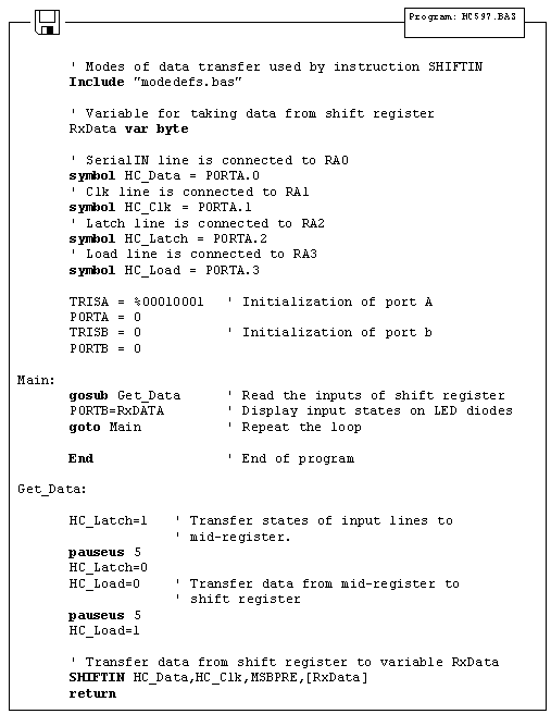
Insufficient number of microcontroller input lines might represent a problem. Instead of switching to another, more expensive microcontroller model, input shift register 74HC597 could be an answer. For connecting input shift register it is necessary to take 4 of microcontroller I/O lines and one Latch line for every next register. This provides you 8 input lines per shift register. Input shift register transfers states of input pins to one mid-register using the Latch signal. After that, Load signal transfers data from mid register to shift register, where from it is sent to the microcontroller via SerialOut and Clk lines.
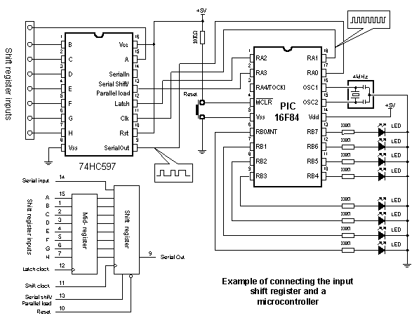
Data transfer between shift registers and a microcontroller is serial. The following program reads states of input shift registers, transfers them to variable RxData and then displays the contents of RxData on diodes connected to port B. For data transfer between shift register and a microcontroller, BASIC instruction SHIFTIN is used.
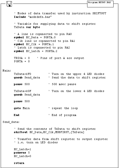
6.8 Output shift register
Insufficient number of output lines might represent a problem with microcontrollers commanding small number of I/O lines, such as PIC16F84. If this is the case, output shift register 74HC595 could be used as an expansion. For connecting it, it is necessary to take 3 of microcontroller I/O lines, thus getting 8 additional output lines. Data transfer between shift register and a microcontroller is serial and commences via the Clk and A lines.
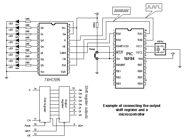
When data is transferred to shift register, Latch signal sends it to output pins. The following program alternately turns on upper and lower LED diodes. For data transfer between shift register and a microcontroller, BASIC instruction SHIFTOUT is used.
6.9 Software serial communication
The easiest way to transfer data between the microcontroller and some other device (for example, PC or another microcontroller) is via RS-232 communication port. This type of communication provides serial asynchronous data transfer over 2 lines (Tx for transmitting and Rx for receiving) within 10m range. In this sample, instructions Serin and Serout are used for creating the software serial communication. Besides voltage level of the signal (RS-232 line interface MAX232 has a role to adjust signal levels on the microcontroller side, i.e. to convert RS-232 voltage levels +/- 10V to TTL levels 0-5V and vice versa) RS-232 features format and transfer rate. Transfer format is 8 data bits, no parity bit and one stop bit, while transfer rate is 2400 bauds.

The program above uses Serin and Serout instructions for sending and receiving data. Data received via Serin instruction is stored into variable B0 and sent back to PC via Serout as a confirmation of successful transfer. Any microcontroller I/O pin can be used for described data transfer.
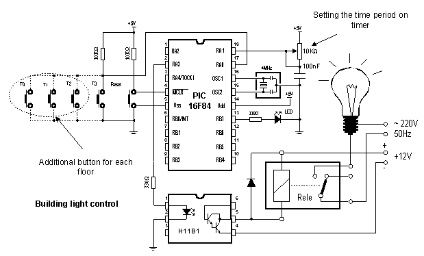
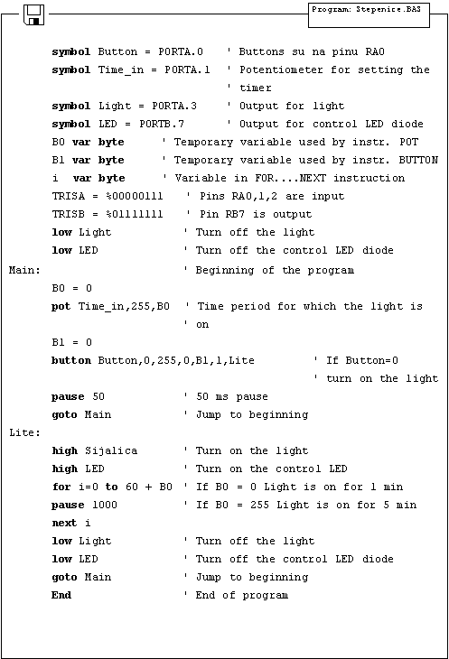
6.10 Building light control
Building light control is a very simple device that is realized using the microcontroller technology lately. The principle is simple - pressing the button turns on the light in the building for a time period T. Upon that time, all lights turn off. Variable T is defined with potentiometer. It is possible to determine for how long will the light be on by reading the potentiometer.

Chapter 7
SAMPLES WITH PIC16F877 MICROCONTROLLER
Introduction
7.1 Keyboard 7.2 Driver for seven-segment displays - MAX7912 7.3 LCD display 7.4 Serial EEPROM 7.5 RS-485 7.6 12-bit A/D converter LTC1290 7.7 12-bit D/A converter LTC1257 7.8 16-bit electrical current D/A converter AD421 7.9 Real time clock PCF8583 7.10 Digital thermometer DS1820
Introduction
This chapter gives detailed examples of connecting PIC16F877 microcontroller to peripheral components and appropriate programs written in BASIC. All of the examples contain electrical connection scheme and program with comments and clarifications. You have the permission to directly copy these examples from the book or download them from the web site www.mikroelektronika.co.yu
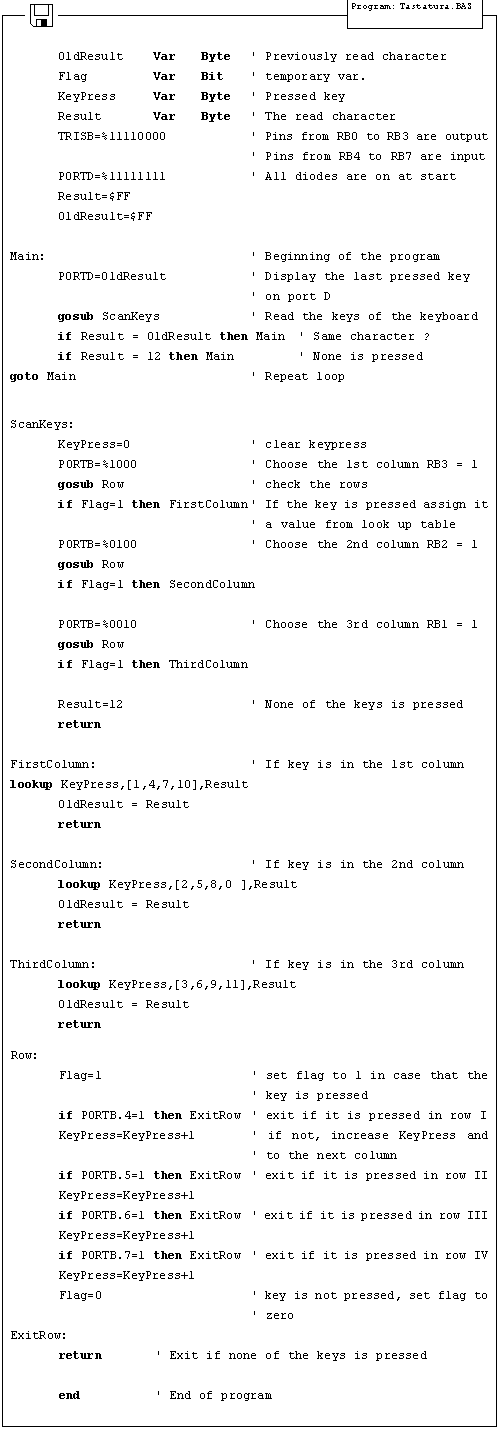
7.1 Keyboard
In more demanding applications that require greater number of buttons, it is possible to use buttons connected in matrix to keep microcontroller I/O lines free. The following sample includes scheme of connecting the keyboard and accompanying program which reads keyboard keys and prints the read value on LED diodes of port D.
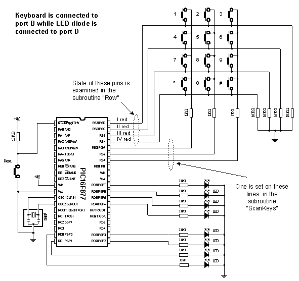
The keys are connected into shared rows and columns. 10K resistors between input pins and the ground determine the state of input pins when the key is not pressed. It means that the logical zero is on input pins when the keys are not pressed. In order to avoid short-circuits between two pressed keys, 1K resistor is added to each row.
Reading the keyboard is done by subroutine "ScanKeys". The keyboard is connected to port B, it's pins being designated as input for rows (RB7, RB6, RB5 and RB4) and output for columns (RB3, RB2 and RB1).
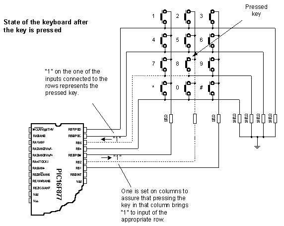
The program sets value of the last read key on port D. If none of the keys is pressed all diodes of port D are on. "*" and "#" are represented with values 10 and 11.
The greatest task is on the subroutine ScanKey. It sets logical one on keyboard columns and then calls the subroutine Row which checks if any of the 4 keys in that columns is pressed (which is signalized by variable Flag).
In case that one of the keys from the column is pressed, variable KeyPress takes value from 0 to 3 (zero for the first row of that column, one for the second row of that column, etc. ). By calling the appropriate Lookup table, real value of the key is stored into variable Result and then to variable OldResult where from it is displayed on port D. In case that no key is pressed value of variable is 12.
7.2 Driver for seven-segment displays - MAX7912
If a PIC16F84 or some similar microcontroller is programmed only to work with seven-segment displays (in multiplex mode) then it could be called "driver". If we supply it with option to communicate, we have a complete driver. If all that is realized directly in silicon while creating the "driver", we get full-fledge drivers that can be sold as independent electronic components.
Question "why use drivers and not multiplexing the digits" is easy to answer with another question "what in case that we need 6 groups of 4 digits display ?". It would require programmer to take care of multiplexing 4x6=24 digits. If the program in question is complicated, time necessary to write and adjust such a program might be more expensive solution than buying a separate driver.
There is a great variety of drivers and we will use MAX7912 in this sample. It can refresh 8 displays with option of configuring light intensity, while data transfer is serial, requiring small number of microcontroller pins. Anyhow, using the driver minimizes the work with seven-segment displays.
Working with driver is simple. There are certain registers which get necessary values via SPI communication. Address value is stored into variable TxAddr and data is stored into TxData. Subroutine Send_Data transfers address and data to driver. Before the first transfer, driver should be initialized by subroutine Init_MAX which is called only at the beginning of the program. The picture below shows the connection scheme and the sample program for printing the numbers 12345678 on displays follows.
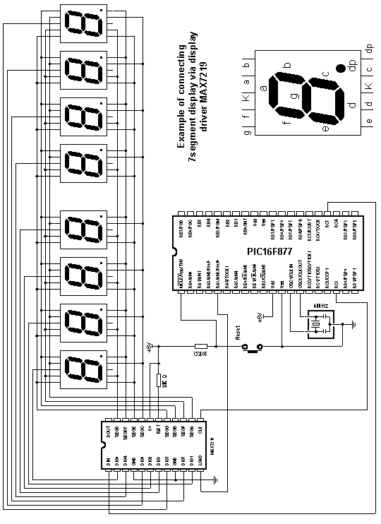
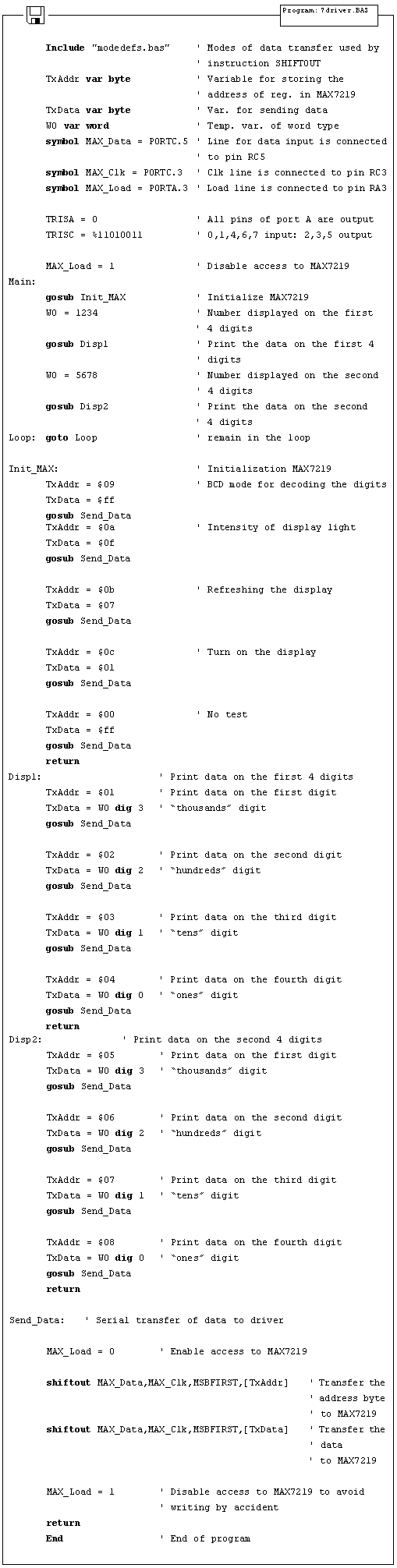
7.3 LCD display
One of the best solutions for devices that require visualizing the data is the "smart" LCD display. Printing the data on this type of display is performed on the dot segments arranged to form a row. Segment dimensions are 7x5 dots and one row can consist of 8, 16, 20 or 40 segments. LCD display can have 1, 2 or 4 rows. LCD can be connected to a microcontroller via 8-bit or 4-bit bus (4 or 8 lines).
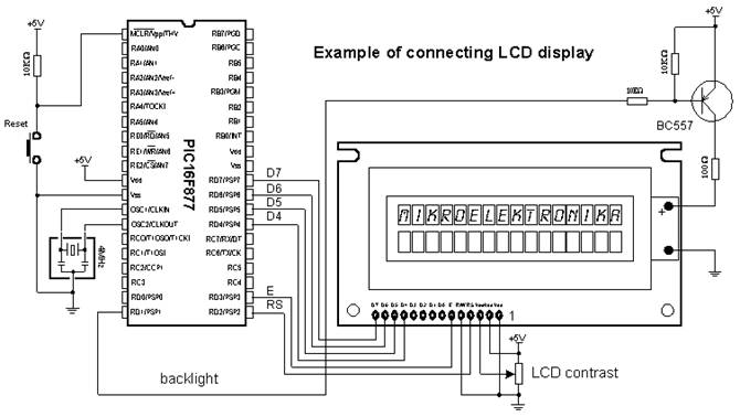
Besides these, there are control lines E (enable), R/W (read/write) and RS (register select) for a total of 7 lines. R/W signal is on the ground, because there is one-way communication toward the LCD display. Some displays feature built-in back-light that can be turned on with RD1 pin via PNP transistor BC557.
The following program uses the BASIC instruction Lcdout for printing the data on LCD display. At the beginning of the program DEFINE directives are used to configure the LCD display.
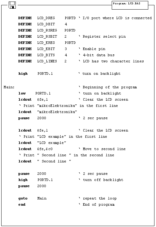
7.4 Serial EEPROM
Data (variables) used by microcontroller are stored in the RAM memory as long as there is microcontroller power supply. When the power is off, contents of RAM memory is gone. If it is necessary to keep the data for later use, it must be stored in permanent memory. One of the memories that can be used for this purpose is serial EEPROM. EEPROM stands for Electrically Erasable and Programmable Read Only Memory. Serial means that EEPROM uses one of the serial protocols (I2C, SPI, microwire) for communication with a microcontroller. This sample will deal with EEPROM from 24Cxx family which uses two lines and I2C protocol for communication with a microcontroller.
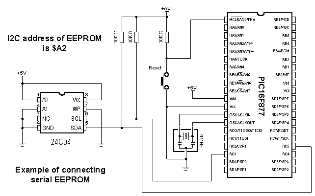
EEPROM is connected to microcontroller via SCL and SDA lines. SCL line is clock for synchronizing the data sent via SDA line. Frequency for transferring the data via SCL and SDA lines goes up to 1MHz.
BASIC instructions I2CWRITE and I2CREAD make reading and writing data to EEPROM pretty simple. To write or read data from EEPROM it is required to write an address of EEPROM (in this case $A2) and address of data in memory as parameters of instruction. EEPROM address is formed in the following way :
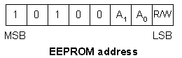
I2C communication allows connecting multiple devices on one line. Therefore, bits A1 and A0 have an option of assigning addresses to certain I2C devices by connecting the pins A1 and A0 to the ground and +5V (one I2C line could be EEPROM on address $A2 and, say, real time clock PCF8583 on address $A0). R/W bit of address byte selects the operation of reading or writing data to memory. More detailed data on I2C communication can be found in the technical documentation of any I2C device.
The following program uses the instruction I2CWRITE to write data from variable EE_byteOut to EEPROM, and then uses the instruction I2CREAD to transfer the same data from EEPROM to variable EE_byteIn and display it on port D diodes.
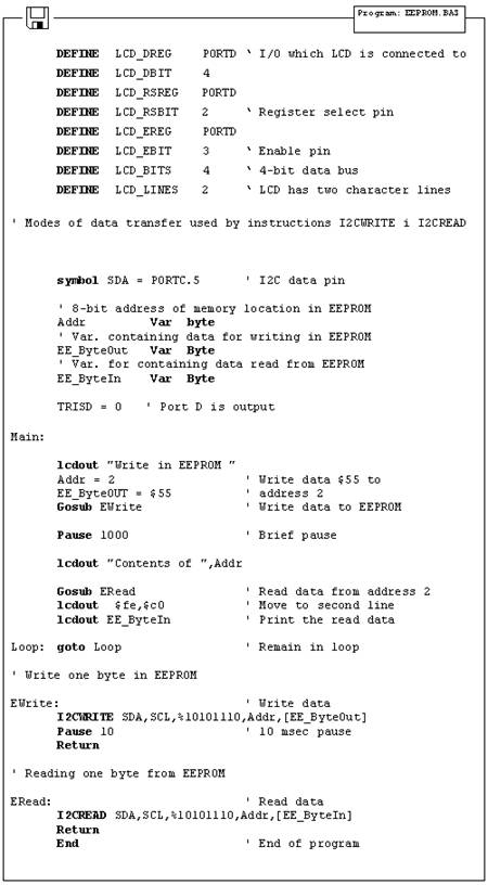
7.5 RS-485
Communication between
two devices is easiest to achieve via serial RS232 communication. However,
there are certain limitations of this type of communication. First of all, it
is meant for local devices in 10-15m radius. The second drawback is that it can
be used with only one device (for example, only one mouse can be connected to
one COM
RS-485 communication goes past these shortcomings, supporting up to 32 devices (even 128) with maximal network length of up to 1500m. The example of connecting 485 interface is shown on the picture below.
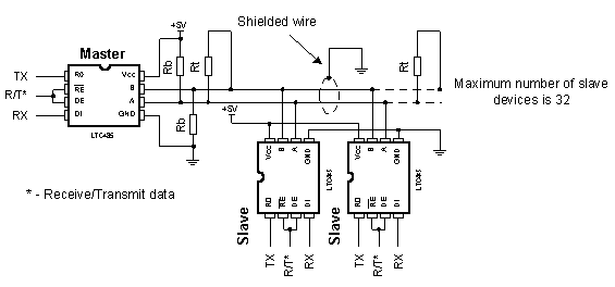
The role of the line interface LTC485 is similar to MAX232 interface with serial communication (adjusting the level). Using the shielded wire is not necessary, but is recommended for reducing the glitch.
Ending resistor Rt should set the specific impendence on the line and usually has value about 100-200 ohms. With lines shorter than 300m, there is no need for ending resistor. Resistors Rb are placed in order to avoid incorrect reading when all the drivers are in receiving mode. Value of these resistors should be 680 ohms if they are placed on single device or 4K7 if they are placed on more than 8 devices in the network. RS485 is a half-duplex communication which uses 2 lines (marked as A and B) for data transfer. The information if data on the receiver side equals binary one or not can be read from the voltage difference of lines A and B. If voltage difference between lines A and B exceeds 200mV data is binary one and if it is lower than -200mV data is binary zero. This method proved very efficient for eliminating great deal of glitch which can occur on the line. As data transfer commences via two lines, organization of sending and receiving the data must be regulated to avoid interference of data on the line. Direction of data (sending or receiving) is determined by state of input pins RE and DE of line interface RS485. When states of pins are RE=0 and DE=1, line interface is set to the receiving mode. When states change to RE=1 and DE=0 line interface changes to the sending mode.
One of the typical solutions for RS485 communication is master/slave communication, where one master device takes over the control while other slave devices get the address which upon they can be called. Communication is initiated by master device sending the same N byte message to all slave devices and going to receiving mode. This N bye sequence contains the address of the specific slave device that is to receive data. Address is commonly located at the beginning of the sequence and consists of one byte (8 bits). When all of the slave devices receive the sequence, they extract the address from it and compare it to their own identification address. Slave device with matching address sends its address to the master device as a confirmation of successful transfer and receives data, while other slave devices return to the receiving mode. Master device receives the address of the mentioned slaved device and that ends the transfer between master and slave devices. In case that slave device does not send its address in some specified (Time out) period of time, master will declare that slave device inactive. This time out period ranges from 10ms to 100ms. The following picture shows format of the sequence that master sends to slave devices.
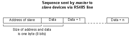
Newer systems consist of PC as master and multiple microcontroller slave devices. One such network is shown on the picture below.
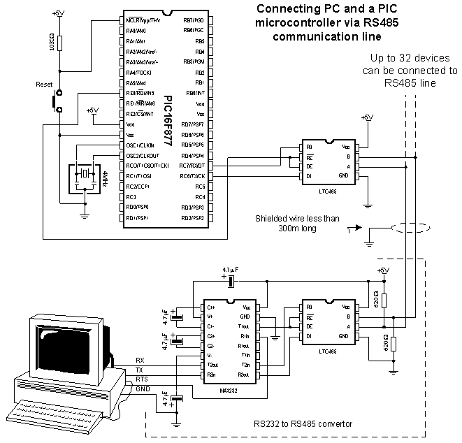
As there is no output for RS485 on PC it is necessary to create RS232 to RS485 converter, while the microcontroller can be directly connected to LTC485 line interface. For physical connection of master and slave devices in RS485 network, RS485 interfaces other than LTC485 may be used - for example, SN75176 manufactured by Texas Instruments.
The following program is an example of connecting one master and up to 8 slave devices. Role of the master is given to the PC which is connected to the network via RS232/RS485 converter. Slave devices are PIC16F877 microcontrollers which are connected to the network via line RS485 interface LTC485 and each one of them owns unique address given as number in 0-7 range. In order to make data received from the master "visible", diodes are connected to port B of every PIC. In the sample, master changes the states of LED diodes on the slaves devices. The following picture represents a window of PC software for communication with PICs via RS485 line.
s
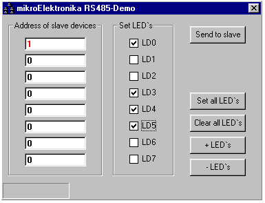
When the button "Send to slave" is clicked, PC sends the address of slave device from the field "Address of slave device" to the RS485 network and it also sends the states of LED diodes as they are set in the group "Set LED's" (total of 2 bytes). All of the PICs receive the address and LED states, but only one of them actually changes LED diode state. That PIC answers by sending its address to PC in 50ms as confirmation of successful receipt and marks the end of the transfer between PC (master device) and PICs (slave devices). In case that PIC does not answer in the expected 50ms, PC will interpret it as if PIC with specified address is not present in the network and will report an error (data transfer is serial, asynchronous at 9600 bauds). Communication with PICs is software based via instructions SERIN2 and SEROUT. The instruction SERIN2 expects a data that matches the address of slave device (in this case, "1" ASCII). Upon receiving the address, next received data is stored into variable B0, it's contents being displayed on port B LED diodes.
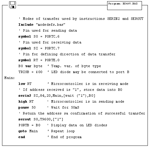
7.6 12-bit A/D converter LTC1290
LTC1290 is a 12-bit AD converter with serial access. It has 8 inputs and thus can measure up to 8 different signals and send them to microcontroller via SPI communication. SPI is abbreviation for Serial Peripheral Device and it is form of master-slave communication.
Microcontroller and AD converter are connected over 4 lines: MOSI, MISO, SS and SCK. The first line is named Master Out Slave In and it is used for instructions that master sends to slaves. The second line is reverse - Master In Slave Out for data master receives from slaves. Line SS (Select Slave) is used for defining which slave will master address, because there can be several slave devices connected to the same communication lines, but with different SS lines. The last line is named Clock indicating that it brings clock to communication between master and selected slave.
Data is sent in form of binary sequence via MISO or MOSI lines and master or slave reads it in the middle of CLK impulse creating synchrony between sent and received message. Although it might sound complicated, it is a pretty simple form of communication for creating software.
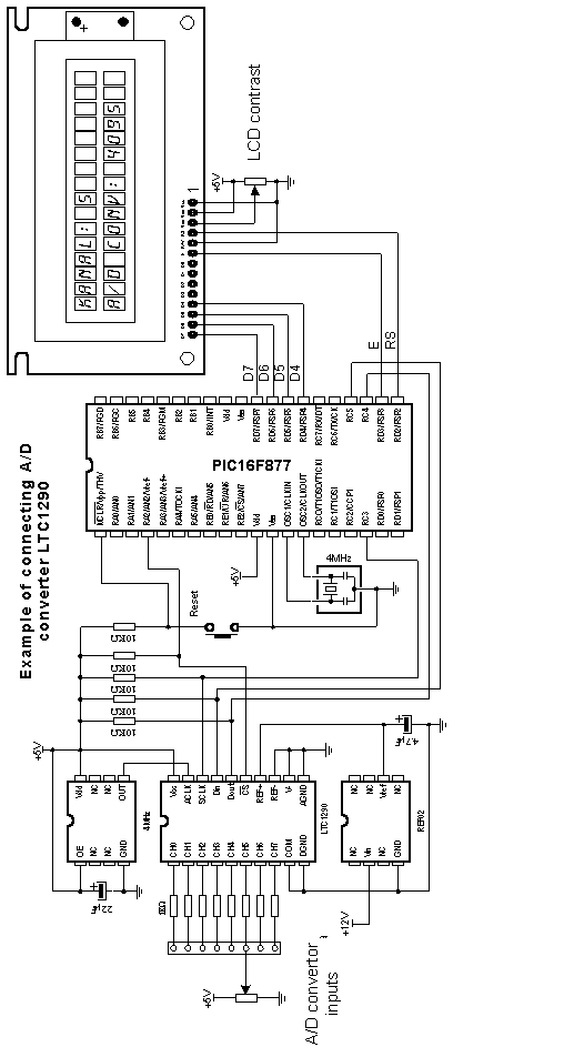
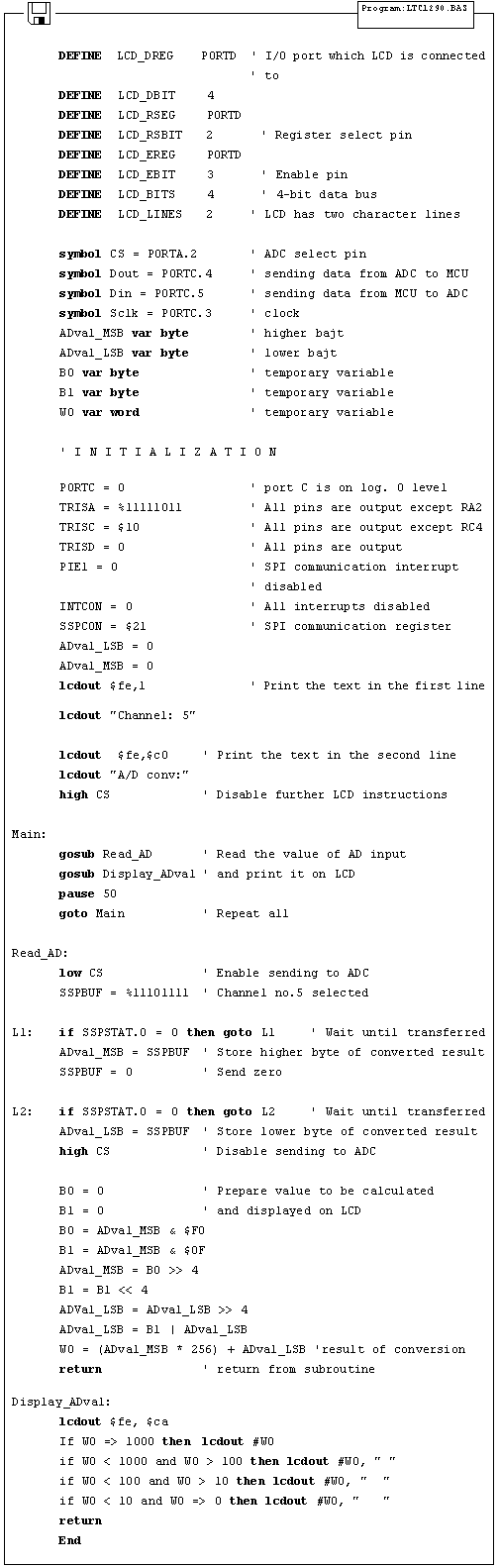
7.7 12-bit D/A converter LTC1257
DA converters convert digital information into voltage (they have much more restricted application than AD converters). In this sample we use LTC1257, 12-bit DA converter with serial access, manufactured by Linear Technology. Type of communication with DA converter is SPI, which is explained in the previous sample. The program sends data containing the desired voltage to the AD converter which translates that data into voltage. We can check the program by measuring voltage on converter's output.
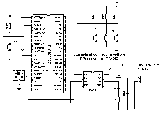
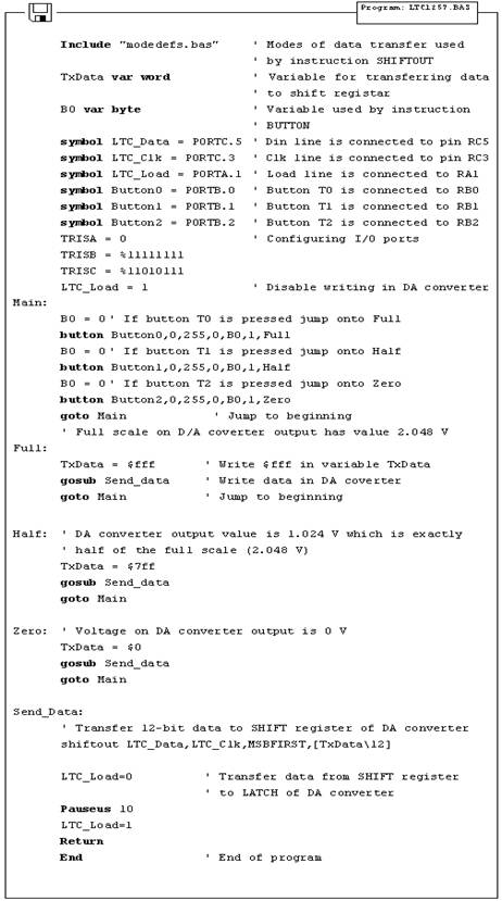
7.8 16-bit electrical current
D/A converter AD421
When talking about DA converters we usually refer to voltage converters. However, there are electric current converters - they simply change the current at output instead of voltage. Current signals are very frequent in industrial applications due to their reliability in information transfer. Common range for electrical current signal in the industrial applications is 4-20mA. Lower limit value (4mA) allows line break or similar malfunctions to be noticed instantly and thus increases safety of signal transfer (when the line breaks or electronics fails, signal drops to 0 mA signalizing the supervising system that the malfunction has occurred). In this sample we used 16-bit DA converter AD421 manufactured by Analog Devices. The program itself is quite simple and it's purpose is to set the lowest, medium and the highest value on the output of DA converter via 3 buttons.
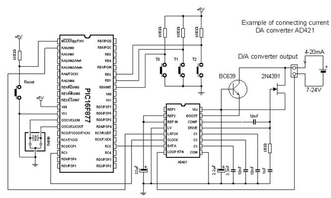
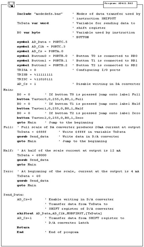
7.9 Real time clock PCF8583
Knowing the real time is of outmost importance in some projects. Let's take for example meteorological observations where we measure temperature, humidity and atmospheric pressure twice a day - these information, without the date and precise time when the measuring took place, would be incomplete. Unless we used real time clock, we would have to utilize microcontroller internal timers to create a second, minute, day, month and a year. Another drawback is the significant cumulative delay that will certainly amount until the end of the year. Even chips intended for special purpose (like the one used in the sample) exhibit significant delays.
For such purpose it is much more efficient to use special chip with it's own power supply, so that time always equals the real time. Accuracy of PCF8583 is about 1 second daily, so that maximal yearly deviation does not exceed 6 minutes (most applications do not require higher accuracy than this).
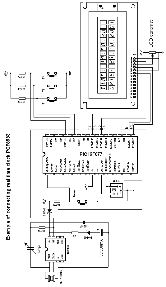
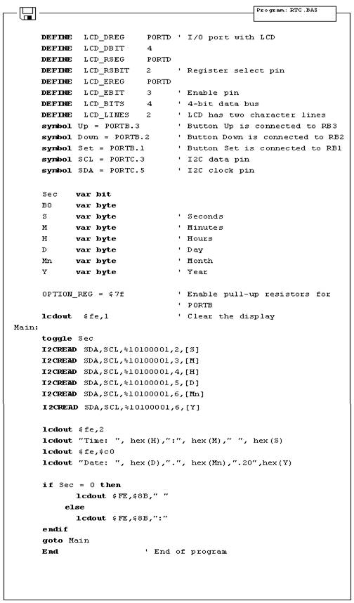
7.10 Digital thermometer DS1820
Temperature measuring is still one of the most common observations. Despite various means of measuring temperature (starting from temperature couples like PT100 all the way to NTC and PTC resistors) new, easier ways are being discovered. One of these new ways was presented by company Dalas with their new chip DS1820. It is a digital temperature sensor with only three pins. The advantage over the mentioned PT100 and NTC sensors which have output in milivolts or ohms (both signals must be converted into digital values in order be handled and displayed) is that DS1820 has digital information in degrees of Celsius, practically solving the problem of analog electronics. It's only limitation is the temperature range, in this case -55 C ~ +125 C. Precision is 0.5 C and the measuring takes 200ms which is more than sufficient, considered the fact that the temperature change is a slow process.
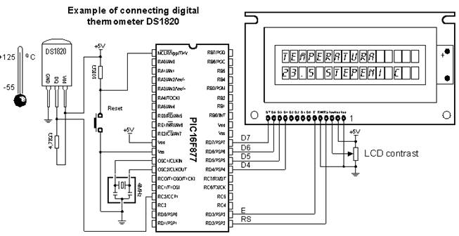
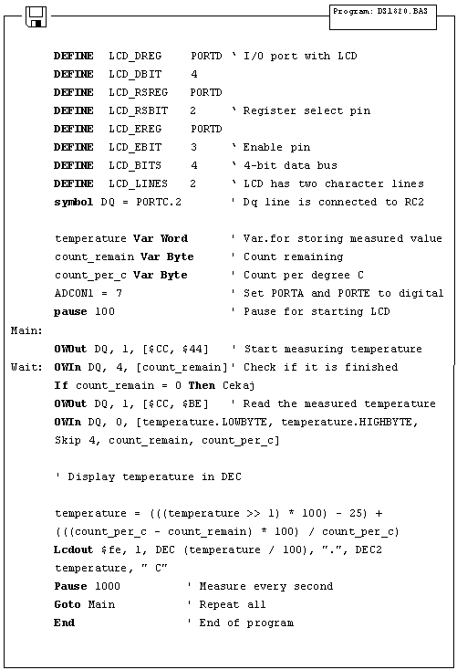
Appendix A
PIC BASIC AND MPLAB
Introduction
A.1 Installation of the program / MPLAB A.2 Connection of PIC BASIC and MPLAB A.3 Toolbar
Introduction
MPLAB is a Windows programming package that facilitates writing and the development of the program. The easiest way to describe it would be to characterize it as a development environment for some standard programming language intended for PC programming. Using MPLAB technically facilitates some of the operations which all the way up to the appearance of the IDE environment, were operating out of the command line with very big number of parameters. Nevertheless, out of different tastes, some programmers even today prefer standard editors and compilers operating out of the command line. In any case the written code is very manifest and provided with a relatively well-provided HELP menu (the abbreviation IDE was born out of the initials Integrated Development Environment).
A.1 Installation of the program / MPLAB

MPLAB is composed out of several different entities
The grouping of the files belonging to the same project (Project Manager)
The creation of the program and its elaboration (Text Editor)
Simulator of the code whereby its work on the microcontroller is simulated.
Besides there exist support for Microchips products such as PICStart Plus i ICD (In Circuit Debugger). As this book doesn't rely upon them, they'll be mentioned as options only.
The minimal requirements in order to start up MPLAB on your computer are:
Compatible PC of 486 class or higher
Microsoft Windows 3.1x or Windows 95 and more recent Windows OS versions
VGA graphic card
8MB of memory space (32 MB recommended)
20MB space on hard disk
The mouse
To start MPLAB it is necessary to install it first, which is understood as a process of copying of MPLAB files from CD onto the hard disk of the PC. On each newly opened window there is button for going back to the previous window so mistakes should not represent any problem. The installation itself flows similarly as those of almost all Windows programs. The welcome screen pops up first and then you have the option choice and the installation menu in order to finally get the message that your installed program is ready to be started.
Steps in the installation:
The starting of the Microsoft Windows
Put the Microchip CD disk into the CD ROM
Click onto the START in the lower left corner of the screen and choose the RUN option
Click onto the BROWSE and select CD ROM drive for your PC
On the CD ROM find the directory under the name of MPLAB
Click onto the SETUP.EXE and then on the OK button
Click once again on OK button in the RUN window
After these seven consecutive steps the installation will start. The following pictures explain the meaning of single steps in the installation process.
The WELCOME screen at the beginning of the installation
At the very beginning it is necessary to choose those components of MPLAB with which we are going to work. As it is supposed that there are no original Microchip's hardware additions such as programming devices or emulators, only the MPLAB environment, Assembler, Simulator and the instructions for use will be installed.
Selection of the components of the MPLAB development environment
The second supposition is that the OS will be Windows 95 (or some more recent version), so that in the selection of the assembler language is taken out everything that is connected to DOS operating system. However if you nevertheless wish to work in DOS, it is necessary to perform the deselecting of all the options connected with Windows, and choose the corresponding DOS components.
Selection of the assembler and OS
As it is normal for any program, MPLAB should be installed into a defined directory. This option can be changed into any directory on any hard disk of your PC. Unless you have some specific reason, it should be left on the selected location.
Selection of the directory for the MPLAB installation
The next option is necessary for the users who already had some previous MPLAB version (different from one that is being installed). It's purpose is to save all the file copies that are subject to change upon the transition to an updated version. In our case the selection of NO assumes that the installation in course is the first one.
The option necessary to the users who install the new version of MPLAB over some already existing installation
The start menu is the set of the pointers onto the programs opened by the click onto the START button in the lower left corner of the screen. It is necessary to leave this option exactly as it is offered, since MPLAB is going to be started from here.
Adding MPLAB into the START menu
Location mentioned next is related to the part of MPLAB which will not be explained here as it is insignificant for users. By selecting an apposite directory, MPLAB will keep all the files in connection with the linker in that directory.
Selection of the directory for the linker files
Every Windows program has the system files, usually stored in the same directory as the Windows itself. After numerous installations, the Windows directory has a tendency of becoming too big and encumbered. Therefore, some of the programs permit their system files to be kept in the same directory as the program itself. MPLAB is one such program so that the option below should be selected.
Selection of the system files directory
Following all steps up to now after pressing the button 'Next' the installation is under way

The screen exactly before the installation
The installation itself is brief and the course of the copying can be monitored on the small screen in the right corner.
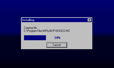
The installation in course
When the installation is terminated, two dialog boxes are present on the screen - one for the last information concerning corrections and the version of the program, the other greeting one. If the text files (Readme.txt) are opened they should be closed.
The last information concerning version and the corrections on the program
By clicking on the Finish button the installation of the program is thereby terminated.
A.2 Connection of PIC BASIC and MPLAB
To make work as easy as possible to those who already got used to the assembler's compiler and MPLAB, Microchip has left the option of using, besides its proper, the compilers of the other manufacturers in its MPLAB development tool. Before starting to write a program, it is necessary to undertake some adjustments. Let's assume that, for example MPLAB is installed in directory: C:\ Program Files \ MPLAB and PIC BASIC Pro compiler in C:\ PBP.
You just start the MPLAB and choose Install Language Tool from the Project menu. The dialog box where the corresponding options is to be set, the manufacturer first, (whereby directly in the next option comes the list of compilers by the same manufacturer) and accordingly the compiler itself - in our case Pic Basic Pro Compiler- and exactly as the one on the picture bellow will appear then. At the end on should click at the option "browse" and find PBP.EXE file on the disk (in this case C: PBP\). By clicking on OK the basic settings are completed.
Start MPLAB and choose the Install Language Tool from the Project menu.
Next step is the creation of the project that is done in a standard way by selecting New Project from the Project menu and by assigning the project name e.g. "probe.pjt". A special care is to be given to the project storage location. The new project and all its components must be located in the same directory as PicBasic Pro! For this case, the project must be stored in C:/PBP.
Creating project by selecting New Project from Project menu and assigning the project name as, e.g. "probe.pjt".
By clicking OK the new window Edit Project appears. In Language Tool "microEngeneering Labs" is to be selected (answer the incoming question with OK). It is, hence, necessary to click on 'probe [.hex]' in the lower part of the window whereby the option Node Properties is activated.
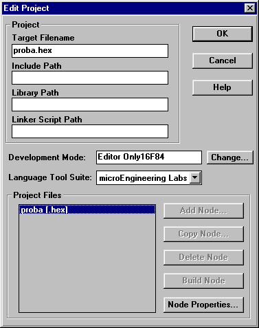
The New window Edit Project for the definition of the manufacturer. Choose "microEngeneering Labs"
The purpose oh this window is to set the microcontroller for which the program is written.
By clicking Change button, the new window for choosing the available microcontrollers appears. As an option, Editor only is to be left in the absence of any available Microchip's tools (this option states the use of MPLAB as a shell for PIC Basic compiler).
Bu clicking Node Properties the window shown on the picture below appears. Choose "PM" version in the assembler selection. Clicking the OK returns us to the previous window.
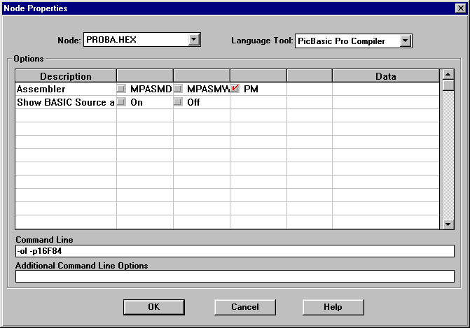
The Add Node button is active now, and through it the name to the file with basic program is assigned. It is in our case, 'probe.bas'. it is to take notice that the present action is only assigning name of the file into the project. Its actual creation is done in next step.
Window for naming the program in writing. Opening of the file is done in next step.
So far we defined microcontroller and the programming language. It still remains to open the file, write the code and register it under the name given in previous step. (proba.bas).
By clicking File-> New the window in which the basic program will be written appears.
Before we start the program writing, file must be registered with the command File-> Save as, file name being obviously "proba.bas". The code writing can start now. The program here serving as an example is a very simple one and its only function is to make the diode on a port B twinkle.
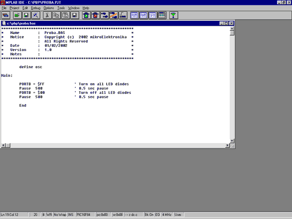
The window for writing Basic program
Upon finishing the code writing, the click on PROJECT-> Build All is performing the compilation of the program. Unless there have been some errors, the obtained file is C:/PBP/probe.hex readable into the microcontroller.
A.3 Toolbar
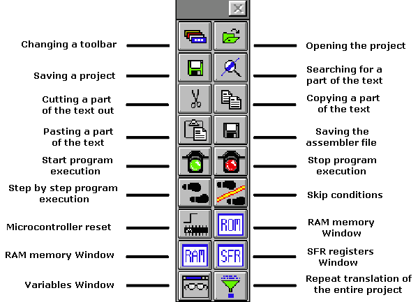
Since MPLAB is composed of several separate parts, each of them possesses its own toolbar. However, there exists a toolbar being a sort of a combination of all the others, which may be considered as a common one. This toolbar is sufficient for our needs so it will be the explained in details. On the picture bellow this toolbar is given with the brief explanations of the icons. Out of the limited format of this book, the basic toolbar is displayed as the free one and in a standard position is always bellow the menu, displaced horizontally along the entire screen.
If, for whatever reason, currently used toolbar does not respond, upon clicking this icon the next toolbar becomes available. The change goes into circle so that upon the 4th click, the same toolbar is obtained again.
|
Appendix B
MicroCODE STUDIO
Introduction
B.1 Installation of the PIC Basic Pro compiler B.2 Installation of a MicroCODE studio B.3 Connecting MicroCODE Studio and PBP compiler B.4 Connecting MicroCODE Studio and the programmer B.5 Code writing and compilation in MicroCODE studio
Introduction
Although the code writing can be done with the simplest editor and compiled in command line (those who had programmed in DOS probably remember well those acrobatics) using special "editors" appropriate for programming language is far better.
Such specialized editors are called "Integrated Development Environments" - IDE. Using them makes code writing easier as the programmer is able to supervise which variables, labels or similar program elements have already been used. At the same time, they make command words bold and even write them in another color rendering thereby program more intelligible. The option for automatic call up of the programmer is also available together with many other facilities. Simply put, having those facilities without using them is like climbing on foot to the 13th floor of a building with elevator.
B.1 Installation of the PIC Basic Pro compiler
The first thing to be done is to create a new directory into which the compiler will stored. Let it be the directory C:/PBP. Then follows the copying of data file PBP240.EXE into that directory and its unpacking (compiler enters in the form of unpacking archive)? by double-clicking it. Unless the compiler is unpacked it is enough to copy it into the desired directory.
B.2 Installation of a MicroCODE studio
Installation of the editor starts by double-clicking on MCSTUDIO. Afterwards, the standard setup process is started where the computer location for the editor's installation can be chosen. The setup process starts with the usual warning to close all other active windows. By clicking on button Next, the setup continues.
The first window after the installation starts. It is necessary to click on button Next
Next question is whether you accept the license and copyright rules or not. By accepting these rules by clicking on the Yes button, the installation goes forward. The next image corresponds to that phase of the installation.
The directory for editor location is the next question. In case of failed statement of the directory, the installation is to be effectuated in C:\ProgramFiles\Mecaniqe.
The choice of an installation directory. The best choice is to leave the option by default. It is necessary to click on OK button in order to proceed
The name and address of directory is without any special meaning for further programming. The real issue is the available memory space on the hard disk or on the need for keeping all items associated with a single program in the same directory.
The next question refers to the name of programming group. The name already offered corresponds to the program name so it should be left as such.
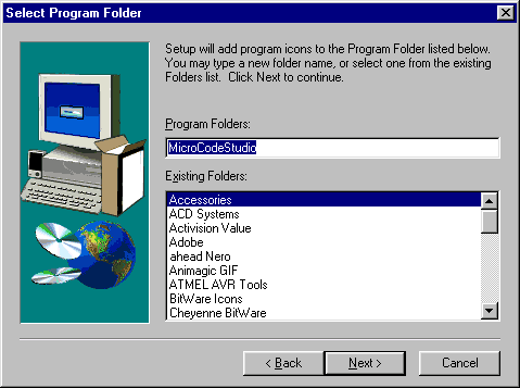
The program group is to be named MicroCodeStudio. Clicking on Next, the installation goes on
Finally, the window appears confirming the successfully performed installation.
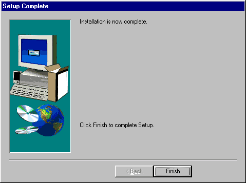
B.3 Connecting MicroCODE Studio and PBP compiler
Clicking on Start-Programs-MicroCode Studio starts up the just installed MicroCode Studio and the window from the picture bellow will appear.
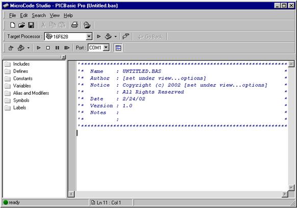
To connect MicroCode Studio and PBP compiler a new window is to be opened. It's done by clicking on the Options from the View menu. If the compiler is already copied into a hard disk directory clicking on the Find Automatically button whereupon will the program itself search for the directory with compiler through the hard disk. When the program finds the compiler, above the button the path "C:\PBP" will appear above the button Find Automatically.
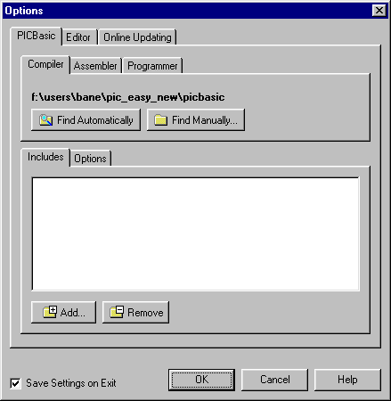
Connecting MicroCode studio and PBP compiler. If the PBP compiler is already copied into a directory on a hard disk, it is enough to click on the Find Automatically button and the program will find it on its own
Beside the path to the compiler, it is still necessary to define the path to the include data file. By clicking on Add the paths C:/PBP and C:/PBP/inc are added within Includes.
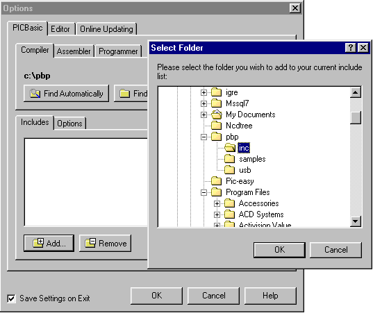
Include data files are necessary for successful compilation of the program. Clicking the Add, the new window appears with the inc directory into which the PBP compiler is copied
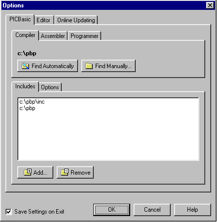
Options window after setting the path to the compiler and include data files. Notice that there are include data files in the very C:\PBP directory so that their path should be specified as well
This step finishes the setting part referring to the compiler. MicroCode studio is now ready for program reading and compiling.
B.4 Connecting MicroCODE Studio and the programmer
The installation of the programmer that MicroCode will call upon successfully accomplished program compilation is to be undertaken only if the user possesses some development environment or some of the programmers that will read in the compiled program into the microcontroller. In lack of any of these tools this part of MicroCode studio setting is to be omitted.
The setting of the programmer starts by clicking on Programmers whereupon two distinct options appear, one for adding of programmer into the list and another for their removal. The programmer that is to be used here ranks as the simplest economic programmers of PIC microcontrollers that are available at the moment. The name of this programmer is ICprog and it uses the serial pin of the computers port in order to communicate with the microcontroller (more details can be found in the special appendix contained in this book).
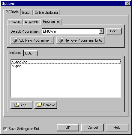
By clicking Programmers the part for setting the programmer appears
Before installing the programmer, it has to be copied in a directory on the hard disc, e.g. "C:\Programmer". Clicking the "Add new Programmer.", the brief procedure of selecting the path to programmer begins.
The first step is writing the name of the programmer or any abbreviation that could bear resemblance to it. As Icprog programmer is used it is logical to name it "ICprog".
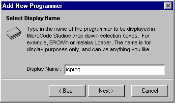
In this option the name of the programmer is to be written. It can well be any of the names bearing resemblance to the programmer we wish to install
The next step is the writing of the exact name of the programmer. It is very important not to make any mistake; otherwise the program will not be able to locate it on a hard disk.
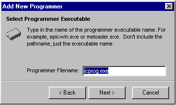
In this option, the exact name of the executive data file of the programmer is to be indicated. In this case it's icprog.exe
Finally, by clicking on Find Automatically, the program then finds on its own the path towards the programmer.
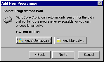
By clicking on Find Automatically the program finds the path to the programmer on its own
Option to define additional parameters is next. Nevertheless, it is to be omitted due to the fact that it will be used in a later phase of the operation when the longer programs are written and the program name is not changed very often. Clicking on Finished overrides this option.
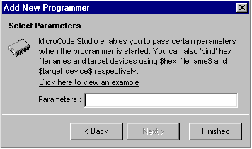
The option to define the additional parameters of the programmer is not to be used here; therefore it is to be omitted by clicking on Finished
The window Option out of the View menu with the set parameters for the compiler and the programmer now looks like exactly as on the image bellow. Thereby all relevant settings of the MicroCode Studio are finished.
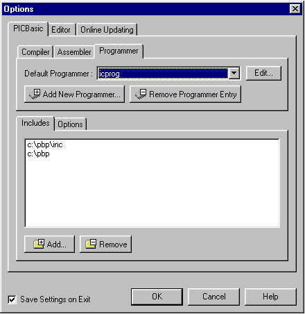
Window Option with all the parameters for the compiler and the programmer set
Besides the setting of the compiler and the programmer, there are somewhat less important settings as that of an editor. Since those parameters are already well set we will not take them into consideration now.
B.5 Code writing and compilation in MicroCODE studio
The MicroCode studio looks like most of the Windows programs. Above the working area there are menu lines, toolbars and the line connected to the compilation and reading of a program into the microcontroller.
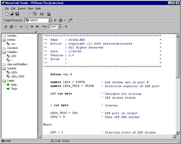
The menu line contains all standard submenus as File, Edit, Search, View and Help.
The toolbar contains but a few basic icons and their purpose we will not explain in details.
What separates the MicroCode studio from the other development environments is its simplicity and legibility. Its most important part is located in the left part by the name Code Explorer. When necessary, that part of the window can be shut down by clicking on View - Code Explorer. although it is recommended to leave it as it is for it contributes to the better legibility and organization of the program. The code writing is done in the right part of the window. The process of code writing itself is largely facilitated by thickening of the commands, and by the excellent solution for the complicated commands with the greater number of parameters as "button" command is. Namely, after writing of this command and the first empty (blank) character, the yellow frame with all parameters of the respective command appear.
Upon having written the code, by clicking on icon Compile Only (in triangular shape on the right side) the compilation of program starts. If an error occurs, it's reported in a special part at the bottom of the window. By clocking on Error, the cursor is positioned exactly at the row in which the error occurred. After correction, the program is compiled as long as the compilation process becomes successful.
If the programmer is already configured, then the icon right next to the Compile Only can be used instead, which will, upon a successfully accomplished compilation, call the programmer.
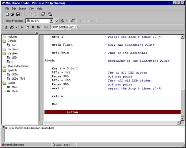
Clicking on the icon in the port form, the special window for examining the serial connection with the microcontroller opens. The Serial communication window serves for the serial communication between PC and the microcontroller. An additional option exists which enables the change of all the transfer parameters such as the port on which the microcontroller is attached, the transfer rate or the transfer format.
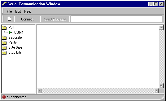
Option for examining the serial connection with the microcontroller
|