![]() Contact breaker
ignition system
Contact breaker
ignition system
Contents
5B.1
Condenser - testing, removal and refitting . . . . . . . . . . . . . . . . . . . . . .5
Contact breaker points - gap and dwell angle adjustment . . . . . . . . .3
Contact breaker points - removal and refitting . . . . . . . . . . . . . . . . . . .4
Distributor - overhaul . . . . . . . . . . . . . . . . . . . . . . . . . . . . . . . . . . . . . .7
Distributor - removal and refitting . . . . . . . . . . . . . . . . . . . . . . . . . . . . .6
Degrees of difficulty
General information . . . . . . . . . . . . . . . . . . . . . . . . . . . . . . . . . . . . . . .1
Ignition HT coil - removal, testing and refitting . . . . . . . . . . . . . . . . . . .9
Ignition system - testing . . . . . . . . . . . . . . . . . . . . . . . . . . . . . . . . . . . .2
Ignition system check . . . . . . . . . . . . . . . . . . . . . . . . . . .See Chapter 1
Ignition timing - adjustment . . . . . . . . . . . . . . . . . . . . . . . . . . . . . . . . .8
Easy suitable for novice with little experience
Fairly easy suitable for beginner with some experience

![]()
![]()
![]()
![]()
![]()
![]()
![]()
![]()
![]()
![]()
![]()
![]()
![]()
![]()
![]()
![]()
![]()
![]()
![]()
![]()
![]()
![]()
![]()
![]()
![]()
![]()
![]()
![]()
![]()
![]()
![]()
![]()
![]()
![]()
![]()
![]()
![]()
![]()
![]()
![]()
![]()
![]()
![]()
![]()
![]()
![]()
![]()
![]()
![]()
![]()
![]()
![]()
![]()
![]()
![]()
![]()
![]()
![]()
![]()
![]()
![]()
![]()
![]()
![]()
![]()
![]()
![]()
![]()
![]()
![]()
![]()
![]()
![]()
![]()
![]()
![]()
![]()
![]()
![]()
![]()
![]()
![]()
![]()
![]()
![]()
![]()
![]()
![]()
![]()
![]()
![]()
![]()
![]()
![]()
![]()
![]()
![]()
![]()
![]()
![]()
![]()
![]()
![]()
![]()
![]()
![]()
![]()
![]()
![]()
![]()
![]()
![]()
![]()
![]()
![]()
![]()
![]()
![]()
![]()
![]()
![]()
![]()
![]()
![]()
![]()
![]()
![]()
![]()
![]()
![]()
![]()
![]()
![]()
![]()
![]()
![]()
![]()
![]() Fairly difficult, suitable for competent DIY mechanic
Fairly difficult, suitable for competent DIY mechanic
Difficult suitable for experienced DIY mechanic
Very difficult, suitable for expert DIY or professional
Specifications
General
Type . . . . . . . . . . . . . . . . . . . . . . . . . . . . . . . . . . . . . . . . . . . . . . . . . . . . Distributor with mechanical contact breaker points Firing order . . . . . . . . . . . . . . . . . . . . . . . . . . . . . . . . . . . . . . . . . . . . . . . 1-3-4-2 (No 1 at crankshaft pulley end of engine) Distributor
Rotational direction of rotor . . . . . . . . . . . . . . . . . . . . . . . . . . . . . . . . . . Anti-clockwise (viewed from cap) Contact breaker points gap . . . . . . . . . . . . . . . . . . . . . . . . . . . . . . . . . . 0.4 mm
Dwell angle . . . . . . . . . . . . . . . . . . . . . . . . . . . . . . . . . . . . . . . . . . . . . . . 47 to 53º
Timing* . . . . . . . . . . . . . . . . . . . . . . . . . . . . . . . . . . . . . . . . . . . . . . . . . . 10º BTDC (crankshaft pulley notch and timing cover rib in alignment)
*Refer to text for information on usage of unleaded petrol
Ignition coil
Primary winding resistance (approximate) . . . . . . . . . . . . . . . . . . . . . . . 1.2 to 1.6 ohm
Secondary winding resistance (approximate) . . . . . . . . . . . . . . . . . . . . . 7k ohms
Torque wrench settings Nm lbf ft
![]() Spark plugs . . . . . . . . . . . . . . . . . . . . . . . . . . .
. . . . . . . . . . . . . . . . . . . . 0 0
Spark plugs . . . . . . . . . . . . . . . . . . . . . . . . . . .
. . . . . . . . . . . . . . . . . . . . 0 0
![]() General
information
General
information
1 In order that the engine can run correctly it is necessary for an electrical spark to ignite the fuel/air mixture in the combustion chamber at exactly the right moment in relation to engine speed and load. The ignition system is based on feeding low tension voltage from the battery to the coil where it is converted to high tension voltage. The high tension voltage is powerful enough to jump the spark plug gap in the cylinders many times a second under high compression, providing that the system is in good condition and that all adjustments are correct.
2 The ignition system is divided into two circuits, low tension and high tension.
3 The low tension circuit (sometimes known as the primary) consists of the battery, lead to the ignition switch, lead from the ignition switch to the low tension or primary coil windings, and the lead from the low tension coil windings to the contact breaker points and condenser in the distributor.
4 The high tension circuit consists of the high tension or secondary coil winding, the heavy ignition lead from the centre of the coil to the centre of the distributor cap, the rotor arm, and the spark plug leads and spark plugs.
5 The system functions in the following manner. Low tension voltage is changed in the coil into high tension voltage by the opening and closing of the contact breaker points in the low tension circuit. High tension voltage is then fed via the carbon brush in the centre of the distributor cap to the rotor arm of the distributor cap, and each time it comes in line with one of the four metal segments in the cap, which are connected to the spark plug leads, the opening and closing of the contact breaker points causes the high tension voltage to build up, jump the gap from the rotor arm to the appropriate metal segment and so via the spark plug lead to the spark plug, where it finally jumps the spark plug gap before going to earth.
6 The ignition is advanced and retarded automatically, to ensure that the spark occurs at just the right instant for the particular load at the prevailing engine speed.
![]() 7 The ignition advance is controlled both 5B
7 The ignition advance is controlled both 5B
mechanically and by a vacuum-operated system. The mechanical governor comprises two weights, which move out from the distributor shaft as the engine speed rises due to centrifugal force. As they move outwards they rotate the cam relative to the distributor shaft, and so advance the spark. The weights are held in position by two light springs and it is the tension of the springs which is largely responsible for correct spark advancement.
8 The vacuum control consists of a diaphragm, one side of which is connected via a small bore tube to the carburettor, and the other side to the contact breaker plate. Depression in the inlet manifold and carburettor, which varies with engine speed and throttle opening, causes the diaphragm to move, so moving the contact breaker plate, and advancing or retarding the spark.
9 A resistance wire in the low tension feed to the coil keeps the coil voltage down to V during normal running. This wire is bypassed when the starter motor is operating, to compensate for reduced battery voltage.
5B.2 Contact breaker ignition system
![]()
![]()
![]()
![]()
![]()
![]()
![]()
![]()
![]()
![]()
![]()
![]()
![]()
![]()
![]()
![]()
![]()
![]()
![]()
![]()
![]()
![]()
![]()
![]()
![]()
![]()
![]()
![]()
![]()
![]()
![]()
![]()
![]()
![]()
![]()
![]()
![]()
![]()
![]()
![]()
![]()
![]() 2 Ignition
system - testing
2 Ignition
system - testing
1 By far the majority of breakdown and running troubles are caused by faults in the ignition system either in the low tension or high tension circuits.
2 There are two main symptoms indicating faults. Either the engine will not start or fire, or the engine is difficult to start and misfires. If it is a regular misfire, (ie the engine is running on only two or three cylinders), the fault is almost sure to be in the secondary or high tension circuit. If the misfiring is intermittent the fault could be in either the high or low tension circuits. If the car stops suddenly, or will not start at all, it is likely that the fault is in the low tension circuit. Loss of power and overheating, apart from faulty carburation settings, are normally due to faults in the distributor or to incorrect ignition timing. Engine fails to start
3 If the engine fails to start and the car was running normally when it was last used, first check that there is fuel in the petrol tank. If the engine turns over normally on the starter motor and the battery is evidently well charged, then the fault may be in either the high or low tension circuits. First check the HT circuit.
4 One of the commonest reasons for bad starting is wet or damp spark plug leads and distributor. Remove the distributor cap. If condensation is visible internally dry the cap with a rag and also wipe over the leads. Refit the cap. If the engine fails to start due to either damp HT leads or distributor cap, a moisture dispersant can be very effective. To prevent the problem recurring, a proprietry damp start product can be used to provide a sealing coat, so excluding any further moisture from the ignition system. In extreme difficulty, a proprietry cold start product will help to start a car when only a very poor spark occurs.
5 If the engine still fails to start, check that voltage is reaching the plugs by disconnecting each plug lead in turn at the spark plug end, and holding the end of the cable with rubber or an insulated tool about mm away from the cylinder block. Spin the engine on the starter motor. Note Do not operate the starter system with the plug leads disconnected in any other way to that described, or damage to system components may result.
6 Sparking between the end of the cable and the block should be fairly strong with a regular blue spark. If voltage is reaching the plugs, then remove them and clean and regap them. The engine should now start.
7 If there is no spark at the plug leads, take off the HT lead from the centre of the distributor cap and hold it to the block as before. Spin the engine on the starter once more. A rapid succession of blue sparks between the end of the lead and the block indicates that the coil is in order and that the
distributor cap is cracked, the rotor arm is faulty or the carbon brush in the top of the distributor cap is not making good contact with the spring on the rotor arm.
8 If there are no sparks from the end of the lead from the coil, check the connections at the coil end of the lead. If it is in order start checking the low tension circuit. Possibly, the points are in bad condition. Clean and reset them as described in this Chapter, Section 3.
9 Use a 12V voltmeter or a 12V bulb and two lengths of wire. With the ignition switched on and the points open, test between the low tension wire to the coil and earth. No reading indicates a break in the supply from the ignition switch. Check the connections at the switch to see if any are loose. Refit them and the engine should run. A reading shows a faulty coil or condenser, or broken lead between the coil and the distributor.
0 Take the condenser wire off the points assembly and with the points open test between the moving point and earth. If there is now a reading then the fault is in the condenser. Fit a new one and the fault is cleared.
1 With no reading from the moving point to earth, take a reading between earth and the distributor terminal of the coil A reading here shows a broken wire which will need to be replaced between the coil and the distributor. No reading confirms that the coil has failed and must be renewed, after which the engine will run once more. Remember to refit the condenser wire to the points assembly. For these tests it is sufficient to separate the points with a piece of dry paper while testing with the points open.
Engine misfires
2 If the engine misfires regularly, run it at a fast idling speed. Pull off each of the plug caps in turn and listen to the note of the engine. Hold the plug cap in a dry cloth or with a rubber glove as additional protection against a shock from the HT supply.
3 No difference in engine running will be noticed when the lead from the defective circuit is removed. Removing the lead from one of the good cylinders will accentuate the misfire.
4 Remove the plug lead from the plug which is not firing and hold it about 6 mm away from the block. Restart the engine. If the sparking is fairly strong and regular, the fault must lie in the spark plug.
5 The plug may be loose, the insulation may be cracked, or the points may have burnt away giving too wide a gap for the spark to jump. Worse still, one of the points may have broken off. Either renew the plug, or clean it, reset the gap, and then test it.
6 If there is no spark at the end of the plug lead, or if it is weak and intermittent, check the ignition lead from the distributor to the plug. If the insulation is cracked or perished, renew the lead. Check the connections at the distributor cap.
![]() 7 If there is still no spark, examine the distributor cap carefully for tracking. This can
be recognised by a very thin black line running between two or more electrodes, or between
an electrode
and
some
other
part
of
the
distributor. These lines are paths which now
conduct electricity across the cap thus letting it run to earth. The only answer is a new
distributor cap.
7 If there is still no spark, examine the distributor cap carefully for tracking. This can
be recognised by a very thin black line running between two or more electrodes, or between
an electrode
and
some
other
part
of
the
distributor. These lines are paths which now
conduct electricity across the cap thus letting it run to earth. The only answer is a new
distributor cap.
8 Apart from the ignition timing being incorrect, other causes of misfiring have already been dealt with under the Selection dealing with the failure of the engine to start. To recap, these are that:
a) The coil may be faulty giving an intermittent misfire.
b There may be a damaged wire or loose connection in the low tension circuit.
c) The condenser may be faulty.
d There may be a mechanical fault in the distributor (broken driving spindle or contact breaker spring).
9 If the ignition timing is too far retarded, it should be noted that the engine will tend to overheat, and there will be a quite noticeable drop in power. If the engine is overheating and the power is down, and the ignition timing is correct, then the carburettor should be checked, as it is likely that this is where the fault lies.
![]()
![]()
![]()
![]()
![]()
![]()
![]()
![]()
![]()
![]()
![]()
![]()
![]()
![]()
![]()
![]()
![]()
![]()
![]()
![]()
![]()
![]()
![]()
![]()
![]()
![]()
![]()
![]()
![]()
![]()
![]()
![]()
![]()
![]()
![]()
![]()
![]()
![]()
![]()
![]()
![]() 3 Contact
breaker points - gap and dwell angle adjustment
3 Contact
breaker points - gap and dwell angle adjustment
1 To adjust the contact breaker points so that the correct gap is obtained, first undo the two distributor cap retaining screws, lift off the cap and withdraw the rotor arm from the distributor shaft. At this stage it is a good idea to clean the inside and outside of the cap and inspect its condition. It is unlikely that the four segments inside the cap will be badly burned or corroded, but if they are the cap must be renewed. If only a small deposit is on the segments, it may be scraped away using a small screwdriver.
2 Push in the carbon brush located in the centre of the cap several times to ensure that it moves freely. The brush should protrude by at least 6 mm.
3 Gently prise the contact breaker points open to examine the condition of their faces. If they are rough, pitted or dirty it will be necessary to remove them to enable new points to be fitted.
4 Assuming that the points are in a satisfactory condition, or that they have been renewed, the gap between the two faces should be measured using feeler blades as follows.
5 Pull off the plug leads, after marking them to ensure correct refitment, and then remove the spark plugs.
6 With the transmission in gear and the handbrake released, slowly pull the car forward, while at the same time watching the distributor, until the heel of the contact
![]() Contact breaker
ignition system 5B.3
Contact breaker
ignition system 5B.3
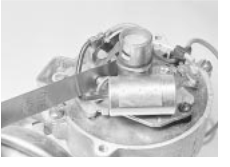
 Checking the contact breaker points gap using a feeler blade
breaker arm is on the peak of one of the four cam lobes. A feeler blade equal to the contact breaker points gap, as given in the Specifications, should now just fit between the contact faces (see illustration) Make sure that the feeler blade is clean - if the contact faces are contaminated with oil or grease, the LT current will be greatly reduced and malfunction will result.
7 If the gap varies from this amount, slacken the contact breaker plate retaining screw and move the breaker plate in or out to achieve the desired gap. The plate can be easily moved with a screwdriver inserted between the notch in the breaker plate and the two adjacent pips in the distributor baseplate.
8 When the gap is correct, tighten the retaining screw and then recheck the gap.
9 Refit the rotor arm, distributor cap, spark plugs and leads.
0 If a dwell meter is available, a far more accurate method of setting the contact breaker points gap is by measuring and setting the distributor dwell angle.
1 The dwell angle is the number of degrees of distributor cam rotation during which the contact breaker points are closed, ie the period from when the points close after being opened by one cam lobe until they are opened again by the next cam lobe. The advantages of setting the points by this method are that any wear of the distributor shaft or cam lobes is taken into account, and also the inaccuracies of using a feeler blade are eliminated. In general, a dwell meter should be used in accordance with the manufacturer's instructions. However, the use
of one type of meter is outlined as follows.
2 To set the dwell angle, remove the distributor cap and rotor arm and connect one lead of the dwell meter to the '+' terminal (15) on the coil and the other lead to the '-' terminal (1 ) on the coil.
3 Whilst an assistant turns on the ignition and operates the starter, observe the reading on the dwell meter scale. With the engine turning on the starter the reading should be as stated in the Specifications.
Note: Fluctuation of the dwell meter needle indicates that the engine is not turning over fast enough to give a steady reading. If this is the case, remove the spark plugs and repeat the checks.
4 If the dwell angle is too small, the contact breaker point gap is too wide, and if the dwell angle is excessive the gap is too small.
5 Adjust the contact breaker points gap, using the method described in paragraph , until the correct dwell angle is obtained.
6 When the dwell angle is satisfactory, disconnect the meter and refit the rotor arm, distributor cap and, if removed, the spark plugs and leads.
7 Check the ignition timing, as described in
Section 8.
![]()
![]()
![]()
![]()
![]()
![]()
![]()
![]()
![]()
![]()
![]()
![]()
![]()
![]()
![]()
![]()
![]()
![]()
![]()
![]()
![]()
![]()
![]()
![]()
![]()
![]()
![]()
![]()
![]()
![]() 4 Contact
breaker points - removal and refitting
4 Contact
breaker points - removal and refitting
1 When significant pitting or burning of the contact faces has occurred, the contact set should be renewed. It is not an expensive item and is worth renewing as a preventive measure at alternate service intervals, even if apparently still in good condition.
Removal
2 Undo the two distributor cap retaining screws, lift off the cap and withdraw the rotor arm from the distributor shaft (see illustration .
3 Move the contact breaker arm spring blade away from the plastic insulator and slip the low tension and condenser lead terminals off the insulator (see illustration .
4 Undo the retaining screw securing the contact breaker plate to the distributor baseplate and lift off the contact set (see illustration .
Refitting
5 Locate the new contact set on the baseplate and refit the retaining screw.
6 Move the contact breaker spring blade away from the insulator, fit the low tension and condenser leads and allow the spring blade to slip back into place. Make sure that the leads and the blade locate squarely in the insulator.
7 Check and adjust the contact breaker points gap or dwell angle, as described in Section then refit the rotor arm and distributor cap.
![]()
![]()
![]()
![]()
![]()
![]()
![]()
![]()
![]()
![]()
![]()
![]()
![]()
![]()
![]()
![]()
![]()
![]()
![]()
![]()
![]()
![]()
![]()
![]()
![]()
![]()
![]()
![]()
![]()
![]()
![]()
![]() 5 Condenser - testing, removal and refitting
5 Condenser - testing, removal and refitting
Testing
1 The purpose of the condenser is to prevent excessive arcing of the contact breaker points, and to ensure that a rapid collapse of the magnetic field, created in the coil and necessary if a healthy spark is to be produced at the plugs, is allowed to occur.
2 The condenser is fitted in parallel with the contact breaker points. If it becomes faulty it will cause ignition failure, as the points will be prevented from cleanly interrupting the low tension circuit
3 If the engine becomes very difficult to start, or begins to miss after several miles of running, and the contact breaker points show signs of excessive burning, then the condition of the condenser must be suspect. A further test can be made by separating the points by hand, with the ignition switched on. If this is accomplished by an excessively strong flash, it indicates that the condenser has failed.
![]() 4 Without special test equipment, the only reliable way to diagnose condenser trouble is
to renew the suspect unit and note if there is
any improvement in performance. It is not an
4 Without special test equipment, the only reliable way to diagnose condenser trouble is
to renew the suspect unit and note if there is
any improvement in performance. It is not an
expensive component and it is worth 5B
considering periodic renewal on a preventive basis, to avoid the inconvenience entailed by failure in use.
Removal
5 To remove the condenser from its location in the distributor, undo the distributor cap retaining screws, lift off the cap and withdraw the rotor arm from the distributor shaft.
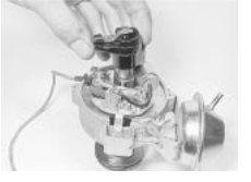
 Removing the rotor arm
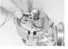
 Slip the low tension and condenser leads out of the insulator
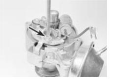
 Undoing the points retaining screw
5B.4 Contact breaker ignition system
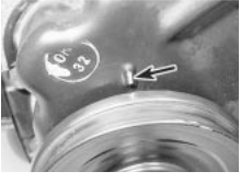
 6.3 Ignition timing marks (arrowed)
in alignment
6 Move the contact breaker arm spring blade away from the plastic insulator and withdraw the condenser lead.
7 Undo the screw securing the condenser to the distributor baseplate and lift the condenser off.
Refitting
8 Refitting is the reverse sequence to removal, but make sure that the condenser and low tension leads are securely located in the insulator behind the contact breaker arm spring blade.
![]()
![]()
![]()
![]()
![]()
![]()
![]()
![]()
![]()
![]()
![]()
![]()
![]()
![]()
![]()
![]()
![]()
![]()
![]()
![]()
![]()
![]()
![]()
![]()
![]()
![]()
![]()
![]()
![]()
![]()
![]()
![]()
![]()
![]()
![]()
![]() 6 Distributor - removal and refitting
6 Distributor - removal and refitting
Removal
1 Pull off the spark plug leads, after marking them to ensure correct refitment, and remove the spark plugs.
2 Undo the distributor cap retaining screws, lift off the cap and place it to one side.
3 With the transmission in gear and the handbrake released, pull the car forward until, with a finger over the plug hole, compression can be felt in No cylinder (the cylinder nearest the crankshaft pulley). Continue moving the car forwards until the notch on the crankshaft pulley is in line with the raised mark on the timing cover (see illustration). The distributor rotor arm should now be pointing to the notch on the rim on the distributor body.
4 Disconnect the distributor low tension lead at the harness connector and detach the vacuum advance pipe from the distributor vacuum unit.
5 Undo the distributor clamp retaining bolt, lift off the clamp plate and withdraw the distributor from its location.
Refitting
6 Before refitting the distributor, check that the engine has not been inadvertently turned whilst the distributor was removed; if it has, return it to the original position, as described in paragraph 3.
7 As the distributor is refitted, the distributor shaft will rotate anti-clockwise slightly due to the meshing action of the skew gears on the distributor shaft and camshaft. To ensure that
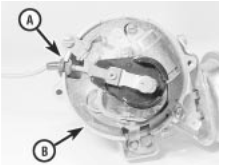
6.7 Distributor rotor position prior to refitting
A LT lead grommet B No1 reference mark
the distributor shaft is in the correct position after fitting, ie with the rotor arm pointing towards the notch in the rim of the distributor body, set the shaft so that the rotor arm is pointing towards the low tension lead grommet in the side of the distributor body
(see illustration , prior to fitting. As the skew gears mesh, the shaft will turn back to the correct position.
8 It is also necessary to position the oil pump driveshaft so that it engages with the slot in the distributor shaft as the distributor is inserted. The shaft should be positioned so that it is at approximately to the crankshaft centreline (see illustration .
9 Make sure that the O-ring seal is in position at the base of the distributor and, with the shafts set as previously described, insert the distributor into its location. It may take two or three attempts to engage the oil pump driveshaft, and finish with the rotor arm pointing to the notch. If necessary move the distributor shaft very slightly one way or the other, until the correct position is achieved.
0 With the distributor in place, turn the distributor body clockwise a few degrees so that the contact breaker points are closed, and then slowly turn it anti-clockwise until they just open with the rotor arm once more pointing towards the notch in the distributor body rim. Hold the distributor in this position and refit the clamp plate and clamp bolt. Tighten the bolt securely.
1 Reconnect the low tension lead and the vacuum advance pipe. Refit the spark plugs, distributor cap and leads.
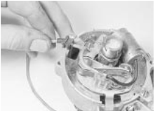
 7.3 Removing the LT lead
![]()
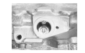

 6.8 Correct position of oil pump
driveshaft prior to fitting distributor
2 Refer to Section 8 and adjust the ignition timing.
![]()
![]()
![]()
![]()
![]()
![]()
![]()
![]()
![]()
![]()
![]()
![]()
![]()
![]()
![]()
![]()
![]()
![]()
![]()
![]()
![]()
![]()
![]()
![]()
![]()
![]()
![]()
![]()
![]()
![]()
![]()
![]()
![]()
![]()
![]()
![]()
![]()
![]() 7 Distributor - overhaul
7 Distributor - overhaul
1 Remove the distributor from the engine, as described in the previous Section, and then prepare a clean uncluttered working area.
2 Remove the rotor arm, ease the contact breaker arm spring blade away from the plastic insulator and slip the low tension and condenser leads off the insulator.
3 Withdraw the low tension lead grommet from the slot in the side of the distributor body
(see illustration) and remove the lead.
4 Undo the retaining screw and lift off the contact set.
5 Undo the retaining screw and lift off the condenser (see illustration .
6 On the side of the distributor body, undo the two vacuum unit securing screws. Withdraw the vacuum unit and at the same time disengage the operating arm from the peg on the side of the baseplate (see illustrations .
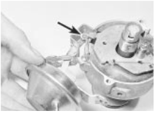
7 Undo the two baseplate securing screws, noting the earth tag under one screw and the spade terminal under the other (see illustration) Withdraw the baseplate assembly from the distributor body.
8 This is the practical limit of dismantling of these distributors, as none of the components below the baseplate are renewable as separate items. If, however, it is necessary to remove the centrifugal advance springs and
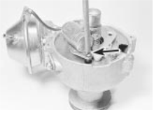
 7.5 Undoing the condenser retaining
screw
![]() Contact breaker
ignition system 5B.5
Contact breaker
ignition system 5B.5
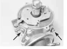
 7.6a Remove the vacuum unit retaining
screws (arrowed) . . .
weights for cleaning or inspection, this can now be done. Mark each spring and its associated locating post with a dab of paint for identification and then carefully hook off the springs. Ensure that the springs and weights are refitted in the same positions otherwise the ignition advance characteristics of the engine will be altered. The weights can be withdrawn after extracting the small retaining clips (see illustration .
9 With the distributor dismantled, clean the mechanical components in paraffin and dry with a lint-free cloth.
0 Check the condition of the contact breaker points, as described in Section . Check the distributor cap for corrosion of the segments and for signs of tracking, indicated by a thin black line between the segments. Make sure that the carbon brush in the centre of the cap moves freely and stands proud by at least 6 mm. Renew the cap if necessary.
1 If the metal portion of the rotor arm is badly burned or loose renew the arm. If slightly burnt, clean the arm with a fine file.
2 Check that the plates of the baseplate assembly move freely, but without excessive slackness. If defective the baseplate assembly must be renewed.
3 Suck on the end of the vacuum unit outlet and check that the operating arm moves in as the suction is applied. Release the suction and check that the arm returns to its original position. If this is not the case, renew the vacuum unit.
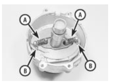
 4 Inspect the distributor body and shaft assembly for excessive side movement of the
shaft in its bushes. With the advance weights
7.8 Centrifugal advance springs (A) and advance weight retaining clips (B)
7.6b . . . and disengage the operating arm
(arrowed) while withdrawing the unit
and springs in position, hold the skew gear at the base of the shaft with one hand, and with the other hand turn the upper shaft clockwise as far as it will go and then release it. Check as this is done, that the advance weights move out and then return under the action of the springs. Finally check the drivegear for wear, chips or pitting of the teeth. It will be necessary to renew the complete distributor if the body, shafts, weights, springs or drivegear are worn or are in any way unsatisfactory.
5 Reassembly of the distributor is a direct reversal of the removal sequence, but apply a few drops of engine oil to the locating pivot posts of the advance weights and to the felt pad at the top of the distributor shaft. After reassembly adjust the contact breaker points, as described in Section and then refit the distributor to the car, as described in Section
![]()
![]()
![]()
![]()
![]()
![]()
![]()
![]()
![]()
![]()
![]()
![]()
![]()
![]()
![]()
![]()
![]()
![]()
![]()
![]()
![]()
![]()
![]()
![]()
![]()
![]()
![]()
![]()
![]()
![]() 8 Ignition
timing - adjustment
8 Ignition
timing - adjustment
Models using leaded (4-star) petrol
1 For prolonged engine life, efficient running performance and economy it is essential for the fuel/air mixture in the combustion chambers to be ignited by the spark plugs at precisely the right moment in relation to engine speed and load. For this to occur the ignition timing must be set accurately and should be checked at the intervals given in Chapter or wherever the position of the distributor has been altered. To make an accurate check of the ignition timing it is necessary to use a stroboscopic timing light, whereby the timing is checked with the engine running at idling speed.
2 If the distributor has been removed, or if for any reason its position on the engine has been altered, obtain an initial setting to enable the engine to be run, as described in Section
Also make sure that the contact breaker points gap or dwell angle is correctly set, as described in Section 3.
3 To check the timing, first highlight the timing marks using white chalk or quick-drying paint. The marks are a notch on the crankshaft pulley and a raised mark on the timing cover (see illustration 6.3 . When they are aligned the engine is at the specified
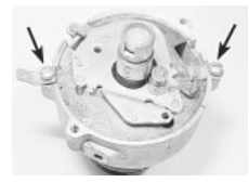

 7.7 Undo the baseplate retaining screws
(arrowed)
number of degrees BTDC when the marks are aligned, not TDC.
4 Run the engine up to its normal operating temperature and then switch off.
5 Connect a timing light to the spark plug lead of No cylinder, following the manufacturer's instructions.
6 With the engine idling, point the timing light at the timing marks. The marks will appear stationary, and if the timing is correct, they will be aligned.
7 If the marks are not aligned, slacken the distributor clamp bolts or retaining nuts and move the distributor body slowly in one direction or the other until the marks line up. Tighten the clamp bolt or retaining nuts and check that the setting has not altered.
![]() 8 Open the throttle slightly and note the movement
of
the
timing
marks.
If
the
centrifugal advance in the distributor is working correctly the marks should appear to
move away from each other as the engine
speed increases. The same should happen if suction is applied to the vacuum advance
pipe after disconnecting it from the carburettor, indicating that the distributor
vacuum unit is satisfactory.
8 Open the throttle slightly and note the movement
of
the
timing
marks.
If
the
centrifugal advance in the distributor is working correctly the marks should appear to
move away from each other as the engine
speed increases. The same should happen if suction is applied to the vacuum advance
pipe after disconnecting it from the carburettor, indicating that the distributor
vacuum unit is satisfactory.
9 After checking the timing, switch off the
engine and disconnect the timing light, if 5B
removed, refit the vacuum pipe to the carburettor.
Models using unleaded petrol
Early (pre February 1985) models
0 On models produced up to February
no adjustment of the ignition timing is necessary if the vehicle is to be run on unleaded fuel (See Chapter 4A for fuel requirement).
Later (February 1985 on) models
1 All models produced after February 1985 are designed to run on unleaded, but the manufacturers state that the ignition should be retarded by 3º, to 7º BTDC.
2 The crankshaft pulley only has one timing mark BTDC), so it will be necessary to make additional marks to accurately retard the ignition.
3 Turn the engine by means of the crankshaft pulley bolt, or by engaging top gear and pulling the car forward, until No 1 piston is at TDC on the firing stroke. This can
5B.6 Contact breaker ignition system
be felt by removing No spark plug and feeling for compression with your fingers as the engine is turned. The precise TDC point will have to be determined using a blunt probe
(such as a knitting needle) inserted through
No 1 spark plug hole.
4 Make a mark on the crankshaft pulley in alignment with the timing mark, or pointer, on the engine.
5 The original pulley mark indicates º BTDC, and the new mark TDC. Using these two markings, measure out a make a third mark on the pulley in the 7ºBTDC position.
6 Using the new timing mark, adjust the ignition timing as described in paragraphs 4 to
7. If detonation occurs, it may be necessary to retard the ignition timing even further; some experimentation may be worthwhile to achieve satisfactory running.
![]()
![]()
![]()
![]()
![]()
![]()
![]()
![]()
![]()
![]()
![]()
![]()
![]()
![]()
![]()
![]()
![]()
![]()
![]()
![]()
![]()
![]()
![]()
![]()
![]()
![]()
![]()
![]()
![]()
![]()
![]()
![]() 9 Ignition HT
coil - removal, testing and refitting
9 Ignition HT
coil - removal, testing and refitting
Removal
1 Disconnect the battery leads.
2 Disconnect the LT wiring connectors from the coil, noting there correct fitted positions.
3 Disconnect the HT lead from the coil.
4 Undo the retaining bolts and remove the coil from the car.
Testing
5 Testing of the coil consists of using a multimeter set to its resistance function, to check the primary (LT '+' to '-' terminals) and secondary (LT to HT lead terminal) windings for continuity, bearing in mind that on the four output, static type HT coil there
![]() are two sets of each windings. Compare the results obtained to those given in the Specifications at the start of this Chapter.
Note the resistance of the coil windings will
vary slightly according to the coil temperature, the results in the Specifications are approximate values for when the coil is at
are two sets of each windings. Compare the results obtained to those given in the Specifications at the start of this Chapter.
Note the resistance of the coil windings will
vary slightly according to the coil temperature, the results in the Specifications are approximate values for when the coil is at
20ºC.
6 Check that there is no continuity between the HT lead terminal and the coil body/mounting bracket.
7 If the coil is thought to be faulty, have your findings confirmed by a Vauxhall dealer before renewing the coil.
Refitting
8 Refitting is a reversal of the relevant removal procedure ensuring that the wiring connectors are correctly and securely reconnected.
|