![]() Cooling, heating and ventilation systems
Cooling, heating and ventilation systems
Contents
Antifreeze mixture . . . . . . . . . . . . . . . . . . . . . . . . . . . . . .See Chapter 1
Coolant level check . . . . . . . . . . . . . . . . . . . . . . . . . . . . .See Chapter 1
Cooling system - draining . . . . . . . . . . . . . . . . . . . . . . . .See Chapter 1
Cooling system - filling . . . . . . . . . . . . . . . . . . . . . . . . . .See Chapter 1
Cooling system - flushing . . . . . . . . . . . . . . . . . . . . . . . .See Chapter 1
Cooling system electrical switches - testing, removal and refitting . . .7
Cooling system hoses - disconnection and renewal . . . . . . . . . . . . . .2
General information and precautions . . . . . . . . . . . . . . . . . . . . . . . . . .1
Heater components - removal and refitting . . . . . . . . . . . . . . . . . . . . .9
Heater/ventilation system - general information . . . . . . . . . . . . . . . . . .8
Radiator - removal, inspection and refitting . . . . . . . . . . . . . . . . . . . . .3
Radiator electric cooling fan - testing, removal and refitting . . . . . . . .6
Thermostat - removal, testing and refitting . . . . . . . . . . . . . . . . . . . . .4
Vents and grilles - removal and refitting . . . . . . . . . . . . . . . . . . . . . . .10
Water pump - removal and refitting . . . . . . . . . . . . . . . . . . . . . . . . . . .5
Degrees of difficulty
Easy suitable for novice with little experience
Fairly easy suitable for beginner with some experience

![]()
![]()
![]()
![]()
![]()
![]()
![]()
![]()
![]()
![]()
![]()
![]()
![]()
![]()
![]()
![]()
![]()
![]()
![]()
![]()
![]()
![]()
![]()
![]()
![]()
![]()
![]()
![]()
![]()
![]()
![]()
![]()
![]()
![]()
![]()
![]()
![]()
![]()
![]()
![]()
![]()
![]()
![]()
![]()
![]()
![]()
![]()
![]()
![]()
![]()
![]()
![]()
![]()
![]()
![]()
![]()
![]()
![]()
![]()
![]()
![]()
![]()
![]()
![]()
![]()
![]()
![]()
![]()
![]()
![]()
![]()
![]()
![]()
![]()
![]()
![]()
![]()
![]()
![]()
![]()
![]()
![]()
![]()
![]()
![]()
![]()
![]()
![]()
![]()
![]()
![]()
![]()
![]()
![]()
![]()
![]()
![]()
![]()
![]()
![]()
![]()
![]()
![]()
![]()
![]()
![]()
![]()
![]()
![]()
![]()
![]()
![]()
![]()
![]()
![]()
![]()
![]()
![]()
![]()
![]()
![]()
![]()
![]()
![]()
![]()
![]()
![]()
![]()
![]()
![]()
![]()
![]()
![]()
![]()
![]()
![]()
![]()
![]()
![]()
![]()
![]() Fairly difficult, suitable for competent DIY mechanic
Fairly difficult, suitable for competent DIY mechanic
Difficult suitable for experienced DIY mechanic
Very difficult, suitable for expert DIY or professional
![]()
Specifications
Thermostat
Opening temperature:
1.3 litre models . . . . . . . . . . . . . . . . . . . . . . . . . . . . . . . . . . . . . . . . . . 1°C All other models . . . . . . . . . . . . . . . . . . . . . . . . . . . . . . . . . . . . . . . . . 2°C
Fully open temperature:
1.3 litre models . . . . . . . . . . . . . . . . . . . . . . . . . . . . . . . . . . . . . . . . . . 103°C All other models . . . . . . . . . . . . . . . . . . . . . . . . . . . . . . . . . . . . . . . . . 107°C Expansion tank cap
Opening pressure . . . . . . . . . . . . . . . . . . . . . . . . . . . . . . . . . . . . . . . . . . 1.20 to 1.35 bar
Fan thermoswitch
Switches on at:
Early models . . . . . . . . . . . . . . . . . . . . . . . . . . . . . . . . . . . . . . . . . . . . 7°C Later models . . . . . . . . . . . . . . . . . . . . . . . . . . . . . . . . . . . . . . . . . . . . 100°C Switches off at . . . . . . . . . . . . . . . . . . . . . . . . . . . . . . . . . . . . . . . . . . . . 3°C
Torque wrench settings Nm lbf ft
Coolant pump bolts:
1.2, 1.3 and 1.4 litre models . . . . . . . . . . . . . . . . . . . . . . . . . . . . . . . . 8 6
1.6, 1.8 and 2.0 litre models . . . . . . . . . . . . . . . . . . . . . . . . . . . . . . . . 5 8
Thermostat housing bolts:
1.3 and 1.4 litre models . . . . . . . . . . . . . . . . . . . . . . . . . . . . . . . . . . . 0 7
1.6, 1.8 and 2.0 litre models . . . . . . . . . . . . . . . . . . . . . . . . . . . . . . . . 5 1
Temperature sender in manifold . . . . . . . . . . . . . . . . . . . . . . . . . . . . . . . 0 7
Temperature sender in thermostat housing . . . . . . . . . . . . . . . . . . . . . . 8 6
Cooling, heating and ventilation systems
![]()
![]() General
information and precautions
General
information and precautions
General information
The cooling system is of pressurised type, comprising of a pump driven by the timing belt, an aluminium crossflow radiator, electric cooling fan, and a thermostat. The system functions as follows. Cold coolant from the radiator passes through the hose to the coolant pump where it is pumped around the cylinder block and head passages. After cooling the cylinder bores, combustion surfaces and valve seats, the coolant reaches the underside of the thermostat, which is initially closed. The coolant passes through the heater and is returned via the cylinder block to the coolant pump.
When the engine is cold the coolant circulates only through the cylinder block, cylinder head, expansion tank and heater. When the coolant reaches a predetermined temperature, the thermostat opens and the coolant passes through to the radiator. As the coolant circulates through the radiator it is cooled by the inrush of air when the car is in forward motion. Airflow is supplemented by the action of the electric cooling fan when necessary. Upon reaching the radiator, the coolant is now cooled and the cycle is repeated.
The electric cooling fan mounted on the rear of the radiator is controlled by a thermostatic switch. At a predetermined coolant temperature the switch actuates the fan.
Precautions
![]() Warning: Do not attempt to remove the expansion tank filler cap or
disturb any part of the cooling system while the engine is hot, as there is a
high risk of
Warning: Do not attempt to remove the expansion tank filler cap or
disturb any part of the cooling system while the engine is hot, as there is a
high risk of
scalding. If the expansion tank filler cap must be removed before the engine and radiator have fully cooled (even though this is not recommended) the pressure in the cooling system must first be relieved. Cover the cap with a thick layer of cloth, to avoid scalding, and slowly unscrew the filler cap until a hissing sound can be heard. When the hissing has stopped, indicating that the pressure has reduced, slowly unscrew the filler cap until it can be removed; if more hissing sounds are
heard, wait until they have stopped before unscrewing the cap completely. At all times keep well away from the filler cap opening.
![]() Warning: If the engine is hot, the electric cooling fan may start
rotating even if the engine is not running, so be careful to
Warning: If the engine is hot, the electric cooling fan may start
rotating even if the engine is not running, so be careful to
keep hands, hair and loose clothing well clear when working in the engine compartment.
Warning: Do not allow antifreeze to come into contact with skin or painted surfaces of the vehicle. Rinse off spills
immediately with plenty of water. Never leave antifreeze lying around in an open container or in a puddle in the driveway or on the garage floor. Children and pets are attracted by its sweet smell. Antifreeze can be fatal if ingested.
![]()
![]()
![]()
![]()
![]()
![]()
![]()
![]()
![]()
![]()
![]()
![]()
![]()
![]()
![]()
![]()
![]()
![]()
![]()
![]() Cooling
system hoses - disconnection and renewal
Cooling
system hoses - disconnection and renewal
Note: Refer to the warnings given in Section 1
of this Chapter before proceeding.
1 If the checks described in Chapter 1 reveal a faulty hose, it must be renewed as follows.
2 First drain the cooling system (see Chapter If the coolant is not due for renewal, it may be re-used if it is collected in a clean container.
3 To disconnect a hose, use a screwdriver to slacken the clips, then move them along the hose, clear of the relevant inlet/outlet union. Carefully work the hose free. While the hoses can be removed with relative ease when new, or when hot, do not attempt to disconnect any part of the system while it is still hot.
4 Note that the radiator inlet and outlet unions are fragile; do not use excessive force when attempting to remove the hoses. If a hose proves to be difficult to remove, try to release it by rotating the hose ends before attempting to free it. If all else fails, cut the hose with a sharp knife, then slit it so that it can be peeled off in two pieces. Although this may prove expensive if the hose is otherwise undamaged, it is preferable to buying a new radiator.
5 When fitting a hose, first slide the clips onto the hose, then work the hose into position. If clamp type clips were originally fitted, it is a good idea to replace them with screw type clips when refitting the hose. If the hose is stiff, use a little soapy water as a lubricant, or soften the hose by soaking it in hot water.
6 Work the hose into position, checking that it is correctly routed, then slide each clip along the hose until it passes over the flared end of the relevant inlet/outlet union, before tightening the clips securely.
7 Refill the cooling system with reference to
Chapter 1.
8 Check thoroughly for leaks as soon as possible after disturbing any part of the cooling system.
![]()
![]()
![]()
![]()
![]()
![]()
![]()
![]()
![]()
![]()
![]()
![]()
![]()
![]()
![]()
![]()
![]()
![]()
![]()
![]()
![]() Radiator - removal, inspection and refitting
Radiator - removal, inspection and refitting
Removal
Note The radiator can be removed with the cooling fan still attached, but due to the limited space available care must be taken to
![]() avoid damaging the radiator If preferred, the cooling fan may be removed first, as described in Section to provide greater
access.
avoid damaging the radiator If preferred, the cooling fan may be removed first, as described in Section to provide greater
access.


![]()
![]()
![]()
![]()
![]()
![]()
![]()
![]()
![]()
![]()
![]()
![]()
![]()
![]()
![]()
![]()
![]()
![]()
![]()
![]()
![]()
![]()
![]() If leakage is the reason for wanting to remove the radiator, bear
in mind that minor leaks can be often be
If leakage is the reason for wanting to remove the radiator, bear
in mind that minor leaks can be often be
cured using a proprietry radiator sealant, with the radiator in situ.
1 Drain the cooling system, (Chapter 1), and disconnect the battery earth terminal.
2 Slacken the retaining clips and detach the radiator top and bottom hoses and also the smaller diameter expansion tank vent hose.
3 Disconnect the two electrical leads at the thermal switch on the side of the radiator.
4 If the cooling fan is still in position, disconnect the electrical leads at the multi-plug adjacent to the fan motor. Release the cable clips securing the wiring harness to the fan cowl bracket and move the harness to one side.
5 On automatic transmission models equipped with a fluid cooler, disconnect and plug the cooler lines at the radiator side tank. Be prepared for fluid spillage, and take care not to allow dirt to enter the cooler lines.
6 Remove the radiator mounting bolts (one on each side at the top). Carefully lift out the radiator, with fan and shroud if not previously removed.
Inspection
7 With the radiator assembly removed it is easier to examine for leaks which will show up as corroded stains. Permanent repairs with this type of radiator are not possible due to the light alloy and plastic composition. A proprietary sealant compound may be tried, but it is better to renew a defective assembly.
8 Clean out the inside of the radiator by flushing (Chapter 1), and also clean the matrix, removing all the dead flies and bugs which reduce the radiator's efficiency. Take this opportunity to inspect the hoses and clips, making sure that all are fit for further use. Refitting
9 Refitting the radiator is the reverse of the removal procedure. Check that the rubber mountings are in good condition and ensure that the bottom location pegs fit correctly on installation. On completion, refill the cooling system and, on automatic transmission models, check the transmission fluid level and top-up if necessary. See Chapter 1 for details.
![]()
![]()
![]()
![]()
![]()
![]()
![]()
![]()
![]()
![]()
![]()
![]()
![]()
![]()
![]()
![]()
![]()
![]()
![]()
![]() Thermostat removal, testing and refitting
Thermostat removal, testing and refitting
Removal
1 Drain the cooling system, saving the coolant if it is fit for re-use (see Chapter . Disconnect the battery earth lead and proceed as described under the relevant sub- heading.
![]() Cooling, heating and ventilation systems 3.3
Cooling, heating and ventilation systems 3.3
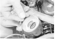
 4.3a Remove the thermostat retaining snap ring . . .
1.2 litre models
2 Disconnect the radiator top hose from the outlet connection at the top of the water pump. This exposes the thermostat and it will be seen that it is retained by a snap-ring.
3 Prise the snap-ring free using a suitable screwdriver blade and then remove the thermostat from the pump outlet (see illustrations .
1.3 and 1.4 litre models
4 Remove the camshaft toothed belt cover, which is secured by five screws.
5 Slacken the clip and detach the radiator top hose from the thermostat housing.
6 Remove the two bolts and detach the thermostat housing (see illustration . On later models the thermostat housing may not be accessible until the camshaft toothed belt back plate has been removed, if necessary remove the plate as described in Chapter 2.
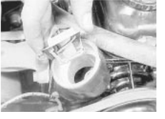
 4.3b . . . and withdraw the
thermostat - 1.2
litre model
7 Remove the thermostat from its recess, noting how the projections on the thermostat fit in cut-outs in the recess (see illustration .
1.6, 1.8 and 2.0 litre models
8 Slacken the clip and detach the radiator top hose from the thermostat housing (see illustration .
9 Unbolt and remove the thermostat cover and extract the thermostat (see illustrations . On 2.0 litre 16-valve models the thermostat is a bayonet fitting in the housing; release it by depressing it and turning with a pair of pointed-nose pliers.
Testing
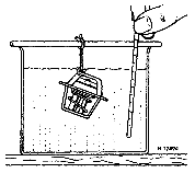
0 A rough test of the thermostat may be made by suspending it with a piece of string in a container full of water. Heat the water to bring it to the boil - the thermostat must open by the time the water boils. If not, renew it.
 Removing the thermostat housing . . .
1 If a thermometer is available, the precise opening temperature of the thermostat may be determined, and compared with the figures given in the Specifications. The opening temperature is also marked on the thermostat
(see illustration
2 A thermostat which fails to close as the water cools must also be renewed. Refitting
1.2 litre models
3 Refitting the thermostat is the reverse sequence to removal, but use a new rubber seal and install the thermostat with the arrow on the web pointing upwards. Refill the cooling system, as described in Chapter 1.
All other models
4 Refit in the reverse order to removal; use a new rubber seal on the thermostat (see illustration) Refill the cooling system, as described in Chapter 1.
![]()


 . . . and withdraw the thermostat from its recess - 1.3 litre model

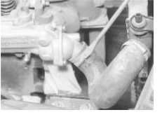
 Slackening the hose clip at the thermostat housing (1.6 litre model
shown)
4.9a Removing the thermostat cover . . .
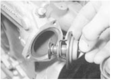
 4.9b . . . and the thermostat itself (1.6 litre model
shown)
4.11 Testing the thermostat
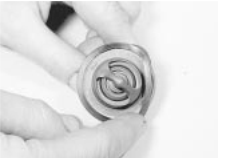
 4.14 Fitting a new seal to the thermostat
Cooling, heating and ventilation systems
![]() disturbed components as described in Chapter Part C. On completion refill the
system as described in Chapter 1.
disturbed components as described in Chapter Part C. On completion refill the
system as described in Chapter 1.
![]()
![]()
![]()
![]()
![]()
![]()
![]()
![]()
![]()
![]()
![]()
![]()
![]()
![]()
![]()
![]()
![]()
![]()
![]()
![]()
![]() 6 Radiator
electric cooling fan - testing, removal and refitting
6 Radiator
electric cooling fan - testing, removal and refitting
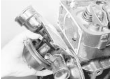
 Removing the water pump - 1.2 litre model
![]()
![]()
![]()
![]()
![]()
![]()
![]()
![]()
![]()
![]()
![]()
![]()
![]()
![]()
![]()
![]()
![]()
![]()
![]()
![]()
![]()
![]()
![]()
![]()
![]()
![]()
![]()
![]()
![]()
![]() 5 Water pump removal and refitting
5 Water pump removal and refitting
Removal
1 Drain the cooling system as described in Chapter then disconnect the battery earth lead. Proceed as described under the relevant sub-heading.
1.2 litre models
2 Remove the auxiliary drivebelt, as described in Chapter 1.
3 Slacken the hose clips and disconnect the three hoses from the pump
4 Remove the six retaining bolts and carefully pull the pump off the head (see illustration). Recover the gasket.
5 If a new pump is being fitted, unbolt and transfer the pump pulley. Transfer the thermostat also, or fit a new one if the old one has seen much service.
6 Before refitting the water pump clean away all traces of old gasket from the pump and cylinder head mating faces.
7 Apply a little grease to a new gasket and place it in position on the pump. Refit the pump and secure the unit with the six bolts tightened progressively to the specified torque.
8 Refit the three hoses and tighten the clips securely. Refit the drivebelt and adjust the tension, as described in Section Finally, refill the cooling system, as described in Section 5, and reconnect the battery.
1.3, 1.4, 1.6, 1.8 and 2.0 litre 8-valve models
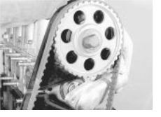
9 Remove the camshaft toothed belt and the toothed belt backplate as described in Chapter 2 Part B.
0 Remove the three securing bolts and withdraw the water pump (see illustration). Note that it may be necessary to remove the alternator completely (see Chapter 5A) to provide enough room to remove the pump from the engine bay.
2.0 litre 16-valve models
1 Working as described in Chapter 2 Part C, removing the following components.
a) Camshaft toothed belt.
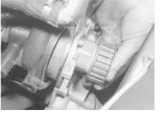
 5.10 Removing the water pump - 1.8 litre model
shown
b Camshaft cover.
c) Camshaft sprockets.
d Toothed belt tensioner and idler rollers. e) Crankshaft sprocket.
f) Toothed belt backplate.
2 Remove the three bolts which secure the water pump to the block. Remove the pump and clean the recess in the block.
Refitting
1.2 litre models
3 If a new pump is being fitted, unbolt and transfer the pump pulley. Transfer the thermostat also, or fit a new one if the old one has seen much service.
4 Before refitting the water pump clean away all traces of old gasket from the pump and cylinder head mating faces.
5 Apply a little grease to a new gasket and place it in position on the pump. Refit the pump and secure the unit with the six bolts tightened progressively to the specified torque.
6 Refit the three hoses and tighten the clips securely. On completion, refit the drivebelt and refill the cooling system (Chapter 1).
1.3, 1.4, 1.6, 1.8 and 2.0 litre 8-valve models
7 Refitting is the reverse of removal, noting the following points.
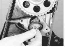
a) Fit a new sealing ring to the pump (see illustration
b Ensure that the pump and its recess are clean and dry and coat the sealing ring and cylinder block mating surface with silicone grease or petroleum jelly. This will prevent contact corrosion between the pump and the block, and make things easier if the pump has to be moved for adjustment of the camshaft toothed belt.
c) Fit the camshaft toothed belt and tension it as described in Chapter 2 Part B and tighten the pump bolts to the specified torque.
d On completion refill the cooling system and adjust the alternator drivebelt as described in Chapter 1.
2.0 litre 16-valve models
8 Refitting is the reverse of removal using a new sealing ring. Tighten the pump mounting bolts to the specified torque then refit all
Testing
1 The cooling fan is supplied with current via the ignition switch, relay and a fuse (see Chapter The circuit is completed by the cooling fan thermostatic switch, which is mounted in the side of the radiator.
2 If a fan does not appear to work, run the engine until normal operating temperature is reached, then allow it to idle. If the fan does not cut in within a few minutes, switch off the ignition and disconnect the wiring plug from the cooling fan switch. Bridge the two contacts in the wiring plug using a length of spare wire, and switch on the ignition. If the fan now operates, the switch is probably faulty and should be renewed.
3 If the fan still fails to operate, check that full battery voltage is available at the feed wire to the switch; if not, then there is a fault in the feed wire (possibly due to a fault in the fan motor, or a blown fuse). If there is no problem with the feed, check that there is continuity between the switch earth terminal and a good earth point on the body; if not, then the earth connection is faulty and must be re-made.
4 If the switch and the wiring are in good condition, the fault must lie in the motor itself. The motor can be checked by disconnecting the motor wiring connector and connecting a
12 volt supply directly to the motor terminals. If the motor is faulty, it must be renewed, as no spares are available.
Removal
5 Disconnect the battery negative terminal.
6 Disconnect the fan motor electrical leads at the multi-plug adjacent to the motor. Release the wiring harness cable-ties at the fan cowl bracket and move the harness to one side.
7 Undo and remove the two small bolts securing the fan cowl to the top of the radiator. Lift the fan and cowl assembly upwards to release the lower mounting lugs and remove the unit from the car.

 5.17 Fitting a new sealing ring to the pump
Cooling, heating and ventilation systems 3.5
![]() 8 To separate the fan motor from the cowl unscrew the three nuts. The fan blades may
be withdrawn from the motor spindle after
removal of the retaining clip.
8 To separate the fan motor from the cowl unscrew the three nuts. The fan blades may
be withdrawn from the motor spindle after
removal of the retaining clip.
9 Further dismantling of the assembly depends on the extent of the problem. If the motor is defective it would be better to have it overhauled by a specialist, as spare parts may be difficult to obtain. The alternative is to renew the motor which may prove cheaper and quicker in the long run.
Refitting
0 Reassembly, if the unit was dismantled, and refitting to the car are the reverse of the dismantling and removal sequences. On completion run the engine up to normal operating temperature and check the fan for correct functioning.
![]()
![]()
![]()
![]()
![]()
![]()
![]()
![]()
![]()
![]()
![]()
![]()
![]()
![]()
![]()
![]()
![]()
![]()
 7 Cooling
system electrical switches - testing, removal and refitting
Electric cooling fan thermostatic switch
Testing
1 Testing of the switch is described in Section 6, as part of the fan test procedure. Removal
2 The switch is located in the side of the radiator (see illustration . The coolant should be cold before removing the switch.
3 Disconnect the battery negative lead. If necessary, firmly apply the handbrake then jack up the front of the vehicle and support it on axle stands (see "Jacking and Vehicle Support Access to the switch can then be gained from underneath the vehicle.
4 Either drain the cooling system to below the level of the switch (as described in Chapter 1), or have ready a suitable plug which can be used to plug the switch aperture in the radiator whilst the switch is removed. If a plug is used, take great care not to damage the radiator, and do not use anything which will allow foreign matter to enter the radiator.
5 Disconnect the wiring plug from the switch.
6 Carefully unscrew the switch from the radiator and recover the sealing ring/washer.
Refitting
7 Refitting is a reversal of removal using a new sealing ring/washer. Securely tighten the switch and top-up/refill the cooling system as described in Chapter 1.
8 On completion, start the engine and run it until it reaches normal operating temperature, then continue to run the engine and check that the cooling fan cuts in and functions correctly. Coolant temperature gauge sender
Testing
9 The coolant temperature gauge, mounted in the instrument panel, is fed with a stabilised voltage supply from the instrument panel feed
(via the ignition switch and a fuse), and its earth is controlled by the sender.
0 The sender is located in the cylinder head, behind the water pump on litre engines, in the inlet manifold on and litre engines, and in the thermostat housing on and
litre engines (see illustration) The sender contains a thermistor, which consists of an electronic component whose electrical resistance decreases at a predetermined rate as its temperature rises. When the coolant is cold, the sender resistance is high, current flow through the gauge is reduced, and the gauge needle points towards the `cold' end of the scale. If the sender is faulty, it must be renewed.
1 If the gauge develops a fault, first check the other instruments; if they do not work at all, check the instrument panel electrical feed. If the readings are erratic, there may be a fault in the voltage stabiliser, which will necessitate renewal of the stabiliser (see Chapter If the fault lies in the temperature gauge alone, check it as follows.
2 If the gauge needle remains at the `cold' end of the scale, disconnect the sender wire, and earth it to the cylinder head. If the needle then deflects when the ignition is switched on, the sender unit is proved faulty, and should be renewed. If the needle still does not move, remove the instrument panel (Chapter 12) and check the continuity of the wiring between the sender unit and the gauge, and the feed to the gauge unit. If continuity is shown, and the fault still exists, then the gauge is faulty, and the gauge unit should be renewed.
3 If the gauge needle remains at the `hot' end of the scale, disconnect the sender wire. If the needle then returns to the `cold' end of the scale when the ignition is switched on, the sender unit is proved faulty and should be renewed. If the needle still does not move, check the remainder of the circuit as described previously.
Removal
4 Either partially drain the cooling system to just below the level of the sender (Chapter 1), or have ready a suitable plug which can be used to plug the sender aperture whilst it is removed. If a plug is used, take great care not to damage the sender unit threads, and do not use anything which will allow foreign matter to enter the cooling system.
5 Disconnect the battery negative lead.
6 Disconnect the wiring from the sender, then unscrew the unit from its location. Refitting
7 Ensure that the sender threads are clean and apply a smear of suitable sealant to them.
8 Refit the sender, tightening it securely, and reconnect the wiring.
9 Top-up the cooling system as described in "Weekly checks"
0 On completion, start the engine and check the operation of the temperature gauge. Also check for coolant leaks.
Fuel injection system coolant temperature sensor
1 Refer to Chapter 4.
![]() 8 Heater/ventilation
system
8 Heater/ventilation
system
![]() general information
general information
The heater operates by passing fresh air, drawn in from the area at the base of the windscreen, through a matrix which is heated by engine coolant.
Temperature regulation is achieved by mixing hot and cold air. Flap valves are used for this; other flap valves direct the air to the windscreen, floor or side outlets.
An electric fan is used to boost airflow through the heater when the normal ram airflow is insufficient, or in extreme climatic conditions.
Fresh air is available at the centre vents, regardless of the heater settings. Stale air is exhausted through grilles towards the rear of the vehicle.
![]()
![]()
![]()
![]()
![]()
![]()
![]()
![]()
![]()
![]()
![]()
![]()
![]()
![]()
![]()
![]()
![]()
![]()
![]()
![]()
![]()
![]()
![]()
![]()
![]()
![]()
![]()
![]()
![]()
![]()
![]()
![]()
![]()
![]()
![]()
![]()
![]() 9 Heater
components removal and refitting
9 Heater
components removal and refitting
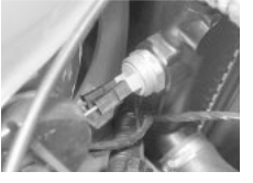
 7.2 Cooling fan thermostatic switch
screwed into side of radiator
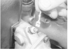
 7.10 Disconnecting the temperature gauge sender
wire (1.8 litre model shown)
Control panel
1 Remove the front half of the centre console, as described in Chapter 11.
2 Remove the radio (if fitted) and its surround, as described in Chapter If a radio is not fitted, remove the blanking plate.
![]() Cooling, heating and ventilation systems
Cooling, heating and ventilation systems
Facia panel
Bulkhead
Blower motor
Centre duct
Centre vent housing
Swivelling vents
Controls
Side grilles
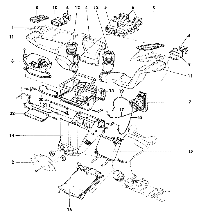

![]()
 Exploded view of heater
components
Side vent housing
Side vent housing
Side ducts
Windscreen ducts
Air distribution housing (upper half)
Air distribution housing (lower half)
Heater matrix
Air distribution housing cover
Air mix (temperature) cable
Upper distribution cable
Lower distribution cable
Air mix flaps
Upper distribution flap
Lower distribution flap
![]() Cooling, heating and ventilation systems 3.7
Cooling, heating and ventilation systems 3.7
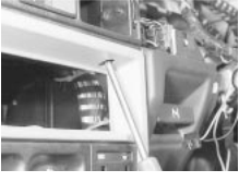
 9.4a Removing a screw from the top of the radio
aperture
3 Detach the three control cables from the air distribution housing, noting their locations for refitting. Their sleeves are colour-coded as follows (see illustration :
Brown - Foot level distribution
White - Hot/Cold air mix
Black - Screen level distribution
4 Remove the two screws from the top of the radio aperture and the two side screws, one on each side (see illustrations .
5 Draw the control panel away (see illustration) To remove it completely, disconnect the wires from the blower switch and (when fitted) the cigarette lighter.
6 Refit in the reverse order to removal. No adjustment of the cable is required: correct length is achieved by the precise location of the cable outer clamps.
Blower motor
7 Remove the wind deflector, (Chapter 11).
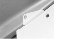
 9.4b Heater control panel side screw
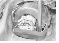
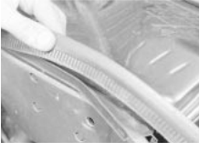
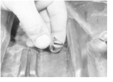
8 Remove the water deflector by freeing it from under the rubber seal and extracting its securing clip (see illustrations) It may also be necessary to slacken or remove one of the wiper spindle nuts.
9 Disconnect the multi-plug, remove the two securing nuts and remove the motor (see illustration .
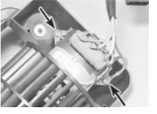
0 If the housing halves are unclipped, the motor and ballast resistor can be removed by undoing the two screws at the resistor end
(see illustration . Spares for the meter are not available, but a competent auto-electrician may be able to repair certain types of fault.
1 Refit in the reverse order to removal.
Heater matrix
2 Remove the front half of the centre console, as described in Chapter 11.
3 Disconnect the control cables from the air distribution housing. Removal of the heater
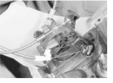
 Removing the heater control panel
control panel is recommended, as described earlier in this Section, to improve access.
4 Under the bonnet, clamp the coolant hoses at the heater matrix stubs (below the steering rack) and disconnect them. Be prepared for coolant spillage.
5 Remove the four screws which secure the air distribution housing cover (see illustrations) The carpet will have to be turned back to get at the lower ones.
6 Disconnect the rear heating duct bellows, when fitted, and remove the air distributor housing cover.
7 Remove the three screws which secure the heater matrix (see illustrations) The air mix flap will have to be moved in order to get at the top two screws. Remove the matrix brackets.
![]()
 8 Withdraw the matrix into the car, keeping it as flat as possible to minimise coolant
spillage.
 9.8a Lift the rubber seal to free the water
 9.8b Water deflector clip
9.9 Removing a blower motor securing nut
 9.10 Blower motor-to-housing
screws
(arrowed)
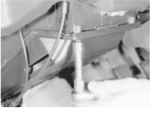
 9.15a Removing an air distribution housing upper
screw
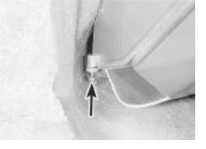
 9.15b Air distribution
housing lower screw
(arrowed)
![]() 3.8 Cooling,
heating and ventilation systems
3.8 Cooling,
heating and ventilation systems
![]()
![]()
![]()
![]()
![]()
![]()
![]()
![]()
![]()
![]()
![]()
![]()
![]()
![]()
![]()
![]()
![]()
![]()
![]()
![]()
![]()
![]()
![]()
![]()
![]()
![]()
![]()
![]()
![]()
![]()
![]() 10 Vents and grilles removal and refitting
10 Vents and grilles removal and refitting
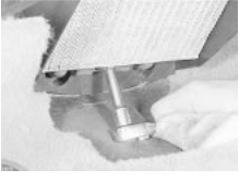
 9.17a Removing the heater matrix lower screw
9 Refit in the reverse order to removal; top- up the cooling system on completion (Weekly checks
Air distribution housing
0 Remove the blower motor and the heater matrix, as described earlier in this Section.
1 Remove the five nuts which secure the facia panel and the pedal bracket to the bulkhead.
2 Remove the steering column switch shrouds. On models with an adjustable column, also remove the adjuster knob and the column lower cover. Refer to Chapter 10 if necessary.
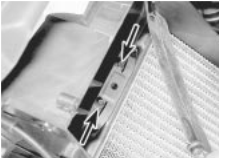
 9.17b Heater matrix upper securing screws (arrowed)
3 Disconnect the hoses and ducts which connect the air distribution housing to the facia panel ducts.
4 Remove the two remaining screws, one at each end, which secure the facia panel. Pull the facia panel away on the passenger side and have an assistant withdraw the air distribution housing, also towards the passenger side.
5 Refit in the reverse order to removal. Use new self-locking nuts when securing the facia panel and pedal bracket to the bulkhead.
6 Top-up the cooling system on completion.
1 The flat grilles at each end of the facia simply unclip. According to equipment level they may also cover a loudspeaker (see illustration .
2 The swivelling vents can be unclipped after swivelling them downwards as far as possible. The side vent housings are secured by a single screw and clips (see illustration) the clips will probably be destroyed during removal.
3 The centre vent housing is secured by four screws, two above and two below (see illustration) The lower screws also secure the radio surround. This housing also carries the clock, when fitted, which must be disconnected when removing the housing.
4 The air extraction grilles on the outside of the vehicle can be carefully prised out of their locations with a wooden or plastic wedge, being careful not to damage the paintwork.
5 All these components can be refitted by simply clipping and/or screwing them back into position
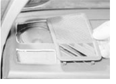
 10.1 Removing an end grille and speaker
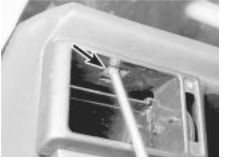
 10.2 Removing a swivelling vent housing securing
screw
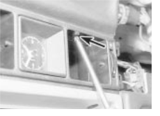
 10.3 Removing a centre vent housing screw
|