5B
Chapter 5 Part B:
Ignition system - fuel injection models
![]() Contents
Contents
Distributor cap (Motronic system) - inspection
Distributor (Motronic system) - dismantling and reassembly
Electronic Control Unit (ECU) - removal and refitting ...................... 8
Engine management system relay assembly (Magneti Marelli system)
renewal
General information and precautions .......... ..... ...... ............. 1
HT leads - maintenance and fitting .......... ..... ...... ................... 4
Degrees of difficulty 20320f515u
Ignition coil - maintenance, testing and renewal ............................. 5
Ignition switch and steering lock
Magneti Marelli system - testing
Sensors (Magneti Marelli system) - removal and refitting ............... 11
Spark plugs - removal, inspection and fitting
TDC sensor (Motronic system) - removal and refitting ................... 10
![]() Easy, suitable for novice with little
experience
Easy, suitable for novice with little
experience
Fairly easy, suitable for beginner with some experience
Fairly difficult, |k
suitable for competent
J^
DIY
mechanic
Difficult, suitable for experienced DIY mechanic
Very difficult,
suitable for expert DIY or professional
5B
![]() Specifications
Specifications
For engine to model applications refer to Chapter 2 System
Model application/Type:
BX 19 GTi (pre July 1990) .......... ..... ...... .......... ..... ...... ....... Bosch LE3 Jetronic
BX 19 GTi 16v (pre 1991) .......... ..... ...... .......... ..... ...... ...... Motronic ML4.1
BX 19 GTi (from July 1990) .......... ..... ...... .......... ..... ...... ..... Motronic MP3.1
BX 19 GTi 16v (from 1991) .......... ..... ...... .......... ..... ...... .... Motronic M1.3
BX 19 TZi with catalytic converter .......... ..... ...... ....................... Motronic M1.3
BX 16 fuel injection .......... ..... ...... .......... ..... ...... ................. Magneti Marelli G6.10
HT leads
Type:
BX 19 GTi .......... ..... ...... .......... ..... ...... .......... ..... ...... Champion LS-10
Spark plugs Type
BX 16 .......... ..... ...... .......... ..... ...... .......... ..... ...... ..... Champion C9YCX
BX 19 GTi .......... ..... ...... .......... ..... ...... .............................. Champion RC7YCC
BX 19 GTi 16v .......... ..... ...... .......... ..... ...... ......................... Champion RC7YCC
Torque wrench settings Nm
Spark plugs:
Taper seat type
Flat seat type (with washer)
Electrode gap
0.9 mm 0.8 mm 1.6 mm
lbf ft
5B 2 Ignition system - fuel injection models
![]()
|
|
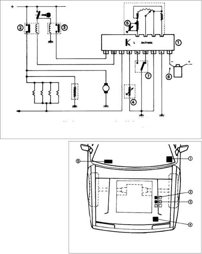
1.2a Wiring diagram for Bosch LE3 Jetronic fuel injection system |
|
7 Electronic control unit (ECU) 2 Injector relay |
|
ECU feed relay Coolant temperature sensor Air temperature sensor |
|
Distributor Throttle position switch |
|
1 General information and precautions |
|
General information Bosch LE3 Jetronic system Fitted to BX 19 GTi models manufactured before July 1990, operation of this system is fully explained in Chapter 4B. The electronic control unit (ECU) incorporated in the system is triggered by the ignition circuit and sends impulses to the injectors, which operate simultaneously and inject fuel in the vicinity of the inlet valves. The ECU is provided with sensors to determine engine temperature, speed and load, and the quantity of air entering the engine (see illustrations). Motronic system Three types of Motronic engine management systems have been fitted to the Citro n BX range, their model applications being as follows: BX
19 GTi 16v (pre 1991) Motronic ML4.1 |
|
1.2b Bosch LE3 Jetronic fuel injection system control unit locations Junction/fusebox 3 ECU feed relay 5 Interface unit (fuel Injector relay 4 Airflow meter/ECU consumption data for computer, if fitted) |
Ignition system - fuel injection models 5B
![]()
|
Operation of these system types is fully explained in Chapter 4C, the main components of the ignition function of each system type being as follows:
a) Electronic control unit (ECU) - located
under the driver's seat, the ECU controls
the system components and receives
signals from various sensors.
b) Ignition coil - for
the Motronic ML4.1 and
M1.
3 systems, a conventional ignition coil
is used, being
triggered by signals from
the ECU. The Motronic MP3.1 system
uses a distributorless ignition system with
a double coil which operates on the
"wasted-spark" principle, supplying
current directly to the spark plugs when
triggered by signals from the ECU
c) HT distributor (all except Motronic MP3.1)
- the
distributor simply distributes HT
current to the spark plugs and consists of
a rotor arm on the end of the camshaft
(inlet camshaft on 16v models) and a
conventional distributor cap.
The following sensors supply the ECU with information:
a) Air temperature sensor - measures the
temperature of the air entering the engine
(integral with the airflow meter)
b) Throttle position
switch - senses the
position
of the throttle valve
c) Coolant temperature sensor
d) Knock sensor (only
fitted to BX 19 GTi
16v with Motronic M1.3)
- senses the
engine vibrations associated with
pre-ignition, which may cause engine
damage unless the ignition timing is
retarded as a preventative measure
e) Lambda (oxygen)
sensor (only fitted to
models
equipped with Motronic M1.3 and
catalytic converter) -
measures the
oxygen content of the exhaust gases
f)
TDC sensor - measures engine speed and
crankshaft position
Magneti Marelli system
Fitted to fuel-injected BX 16 models, operation of this system is fully explained in Chapter 4D.
On the ignition side of this system, the ECU has full control. The ignition system is of the static, distributorless type and consists solely of an ignition HT coil with four outputs. The ignition coil comprises two separate HT coils which supply two cylinders each (one coil supplies cylinders 1 and 4 - the other coil cylinders 2 and 3). Under control of the ECU, the ignition coil operates on the "wasted-spark" principle, ie. each spark plug sparks twice for every cycle of the engine, once on the compression stroke and once on the exhaust stroke.
The ECU uses its inputs from the various sensors to calculate the required ignition advance setting and coil charging time. These sensors are as follows: a) Manifold absolute pressure (MAP) sensor
- informs the ECU of engine load
b) Crankshaft sensor -
informs the ECU of
crankshaft position and
engine speed
c)
Throttle potentiometer - informs the ECU
of
throttle valve position and rate of
throttle opening/closing
d)
Coolant temperature sensor - informs the
ECU of engine temperature
e)
Fuel/air mixture
temperature sensor -
informs the ECU of temperature of fuel/air
mixture charge entering cylinders
f)
Lambda (oxygen) sensor - informs the
ECU
of oxygen content of exhaust gases
Precautions
General
Refer to the precautions listed in Part A of this Chapter.
Engine management systems
Engine management modules are very sensitive components and certain precautions must be taken to avoid damaging them. These are as follows:
|
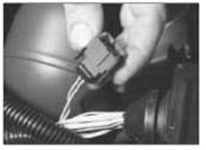
2.3 Magneti Marelli system diagnostic connector |
a)
Although underbonnet-mounted modules
will tolerate normal
underbonnet
conditions, they can be adversely affected
by excess heat or moisture. If using
pressure washing equipment in the
vicinity of the module, take care not to
direct jets of water or steam at the
module. If this cannot be avoided, remove
the module from the vehicle and
protect
its wiring plug with a plastic bag.
b) On models with
underbonnet-mounted
modules, do not run the engine with the
module detached from
the body panel, as
the body acts as an effective heat sink
and the module may be damaged due to
internal overheating.
c)
Do not attempt to improvise fault
diagnosis
procedures using a test lamp or
multimeter, as
irreparable damage could
be caused to the module.
d)
After working on
engine management
system components, ensure that all wiring
is correctly reconnected before
reconnecting the battery or switching on
the ignition.
2 Magneti Marelli system
testing
If a fault appears in the system, first
ensure
that all system wiring connectors are securely
connected and free of corrosion.
Ensure that any fault
is not due to poor
maintenance. That is, check that the air
cleaner
element is clean, the spark plugs are
in good
condition and correctly gapped, that
the valve
clearances are correctly adjusted
and that
the engine breather hoses are clear
and
undamaged.
If these checks fail to
reveal the cause of
the
problem, the vehicle should be taken to a
Citro n dealer for testing. A
wiring block
connector
is incorporated in the engine
management
circuit, into which a special
electronic
diagnostic tester can be plugged
(see illustration). The tester will locate the
fault
quickly and simply, alleviating the need
to test all the system
components individually,
which is a time-consuming operation that
carries a high risk of damaging the ECU.
3 Spark plugs - removal,
inspection and fitting -
Refer to the information given in Section 2 in Part A of this Chapter, noting that the flat-seated spark plugs with washers are also fitted to BX 19 GTi and BX GTi 16 valve engines.
4
HT leads -
maintenance and 5B
fitting
Where applicable, refer to Section 3 in Part A of this Chapter.
5 Ignition coil - maintenance, testing and renewal
Maintenance and testing
1 Refer to Section 4 in Part A of this Chapter.
Renewal
Bosch LE3 Jetronic system
Ignition coil type and
location on the BX 19
GTi manufactured before July 1990 differs to
that on other models in the
range.
The coil is mounted on the underside of the
air inlet manifold (see illustration).
To remove the coil,
detach the wiring
connectors and unbolt the
unit, complete with
its retaining bracket.
Refitting is a
reversal of the removal
procedure.
5B
|