![]() OHV engine
OHV engine
Contents
Ancillary components - removal and refitting . . . . . . . . . . . . . . . . . . . .6
Camshaft and tappets - removal and refitting . . . . . . . . . . . . . . . . . .18
Compression test - description and interpretation . . . . . . . . . . . . . . . .2
Crankshaft and main bearings - removal and refitting . . . . . . . . . . .20
Crankshaft rear oil seal - removal and refitting . . . . . . . . . . . . . . . . .19
Cylinder head - overhaul . . . . . . . . . . . . . . . . . . . . . . . . . . . . . . . . . . .9
Cylinder head - removal and refitting . . . . . . . . . . . . . . . . . . . . . . . . .8
Cylinder head and pistons - decarbonising . . . . . . . . . . . . . . . . . . . .10
Engine oil and filter - renewal . . . . . . . . . . . . . . . . . . . . .See Chapter 1
Engine oil level check . . . . . . . . . . . . . . . . . . . . . . .See Weekly checks
Engine - initial start-up after overhaul . . . . . . . . . . . . . . . . . . . . . . . .24
Engine - removal and refitting . . . . . . . . . . . . . . . . . . . . . . . . . . . . . .23
Engine components - examination and renovation . . . . . . . . . . . . . .21
Engine dismantling and reassembly - general . . . . . . . . . . . . . . . . . . .5
Degrees of difficulty
2A.1
Engine lubrication system - general description . . . . . . . . . . . . . . . .22
Engine/transmission mountings - removal and refitting . . . . . . . . . .17
Flywheel - removal and refitting . . . . . . . . . . . . . . . . . . . . . . . . . . . .16
General description . . . . . . . . . . . . . . . . . . . . . . . . . . . . . . . . . . . . . . .1
General engine checks . . . . . . . . . . . . . . . . . . . . . . . . . .See Chapter 1
Oil pump - overhaul . . . . . . . . . . . . . . . . . . . . . . . . . . . . . . . . . . . . . .13
Oil pump - removal and refitting . . . . . . . . . . . . . . . . . . . . . . . . . . . .12
Operations possible with the engine in the car . . . . . . . . . . . . . . . . . .3
Operations requiring engine removal . . . . . . . . . . . . . . . . . . . . . . . . .4
Pistons and connecting rods - removal and refitting . . . . . . . . . . . .15
Sump - removal and refitting . . . . . . . . . . . . . . . . . . . . . . . . . . . . . . .11
Timing gear components - removal and refitting . . . . . . . . . . . . . . .14
Valve clearances - adjustment . . . . . . . . . . . . . . . . . . . . . . . . . . . . . .7
Easy suitable for novice with little experience
Fairly easy suitable for beginner with some experience

![]()
![]()
![]()
![]()
![]()
![]()
![]()
![]()
![]()
![]()
![]()
![]()
![]()
![]()
![]()
![]()
![]()
![]()
![]()
![]()
![]()
![]()
![]()
![]()
![]()
![]()
![]()
![]()
![]()
![]()
![]()
![]()
![]()
![]()
![]()
![]()
![]()
![]()
![]()
![]()
![]()
![]()
![]()
![]()
![]()
![]()
![]()
![]()
![]()
![]()
![]()
![]()
![]()
![]()
![]()
![]()
![]()
![]()
![]()
![]()
![]()
![]()
![]()
![]()
![]()
![]()
![]()
![]()
![]()
![]()
![]()
![]()
![]()
![]()
![]()
![]()
![]()
![]()
![]()
![]()
![]()
![]()
![]()
![]()
![]()
![]()
![]()
![]()
![]()
![]()
![]()
![]()
![]()
![]()
![]()
![]()
![]()
![]()
![]()
![]()
![]()
![]()
![]()
![]()
![]()
![]()
![]()
![]()
![]()
![]()
![]()
![]()
![]()
![]()
![]()
![]()
![]()
![]()
![]()
![]()
![]()
![]()
![]()
![]()
![]()
![]()
![]()
![]()
![]()
![]()
![]()
![]()
![]()
![]()
![]()
![]()
![]() Fairly difficult, suitable for competent DIY mechanic
Fairly difficult, suitable for competent DIY mechanic
Difficult suitable for experienced DIY mechanic
Very difficult, suitable for expert DIY or professional
Specifications
![]() 2A
2A
General
Maker's designation . . . . . . . . . . . . . . . . . . . . . . . . . . . . . . . . . . . . . . . . 12 SC
Bore x stroke . . . . . . . . . . . . . . . . . . . . . . . . . . . . . . . . . . . . . . . . . . . . . 79.0 x 61.0 mm Cubic capacity . . . . . . . . . . . . . . . . . . . . . . . . . . . . . . . . . . . . . . . . . . . . 1196 cc Compression ratio . . . . . . . . . . . . . . . . . . . . . . . . . . . . . . . . . . . . . . . . . 9.0: 1
Valve clearances (warm)
Inlet . . . . . . . . . . . . . . . . . . . . . . . . . . . . . . . . . . . . . . . . . . . . . . . . . . . . . 0.15 mm Exhaust . . . . . . . . . . . . . . . . . . . . . . . . . . . . . . . . . . . . . . . . . . . . . . . . . . 0.25 mm Cylinder head
Identification mark . . . . . . . . . . . . . . . . . . . . . . . . . . . . . . . . . . . . . . . . . E Valve seat width:
Inlet . . . . . . . . . . . . . . . . . . . . . . . . . . . . . . . . . . . . . . . . . . . . . . . . . . . 1.25 to 1.50 mm
Exhaust . . . . . . . . . . . . . . . . . . . . . . . . . . . . . . . . . . . . . . . . . . . . . . . . 1.60 to 1.85 mm
Overall height . . . . . . . . . . . . . . . . . . . . . . . . . . . . . . . . . . . . . . . . . . . . . 81 ± 0.25 mm
Valves and guides Inlet Exhaust Overall length . . . . . . . . . . . . . . . . . . . . . . . . . . . . . . . . . . . . . . . . . . . . . 99.3 mm 101.1 mm Head diameter . . . . . . . . . . . . . . . . . . . . . . . . . . . . . . . . . . . . . . . . . . . . 32 mm 29 mm Stem diameter (nominal, ± 0.005 mm):
Standard . . . . . . . . . . . . . . . . . . . . . . . . . . . . . . . . . . . . . . . . . . . . . . . 7.005 mm 6.995 mm Oversize 1 . . . . . . . . . . . . . . . . . . . . . . . . . . . . . . . . . . . . . . . . . . . . . . 7.080 mm 7.060 mm Oversize 2 . . . . . . . . . . . . . . . . . . . . . . . . . . . . . . . . . . . . . . . . . . . . . . 7.155 mm 7.1 35 mm Oversize A . . . . . . . . . . . . . . . . . . . . . . . . . . . . . . . . . . . . . . . . . . . . . . 7.255 mm 7.235 mm
Valve guide bore (± 0.01 mm):
Standard . . . . . . . . . . . . . . . . . . . . . . . . . . . . . . . . . . . . . . . . . . . . . . . 7.035 mm Oversize 1 . . . . . . . . . . . . . . . . . . . . . . . . . . . . . . . . . . . . . . . . . . . . . . 7.110 mm Oversize 2 . . . . . . . . . . . . . . . . . . . . . . . . . . . . . . . . . . . . . . . . . . . . . . 7.185 mm Oversize A . . . . . . . . . . . . . . . . . . . . . . . . . . . . . . . . . . . . . . . . . . . . . . 7.285 mm
Valve clearance in guide:
Inlet . . . . . . . . . . . . . . . . . . . . . . . . . . . . . . . . . . . . . . . . . . . . . . . . . . . 0.01 5 to 0.045 mm
Exhaust . . . . . . . . . . . . . . . . . . . . . . . . . . . . . . . . . . . . . . . . . . . . . . . . 0.035 to 0.065 mm
Sealing face angle . . . . . . . . . . . . . . . . . . . . . . . . . . . . . . . . . . . . . . . . . 4°
![]() 2A.2 OHV engine
2A.2 OHV engine
Camshaft
Radial run-out . . . . . . . . . . . . . . . . . . . . . . . . . . . . . . . . . . . . . . . . . . . . . 0.03 mm max Endfloat . . . . . . . . . . . . . . . . . . . . . . . . . . . . . . . . . . . . . . . . . . . . . . . . . . 0.17 to 0.43 mm Cam lift . . . . . . . . . . . . . . . . . . . . . . . . . . . . . . . . . . . . . . . . . . . . . . . . . . 6.45 mm
Pistons and bores Diameters Marking
Production size 1 . . . . . . . . . . . . . . . . . . . . . . . . . . . . . . . . . . . . . . . . . . 78.95 mm 5
78.96 mm 6
78.97 mm 7
78.98 mm 8
Production size 2 . . . . . . . . . . . . . . . . . . . . . . . . . . . . . . . . . . . . . . . . . . 78.99 mm
79.00 mm
79.01 mm
79.02 mm
Production size 3 . . . . . . . . . . . . . . . . . . . . . . . . . . . . . . . . . . . . . . . . . . 79.03 mm
79.04 mm
79.05 mm
79.06 mm
Production size 4 . . . . . . . . . . . . . . . . . . . . . . . . . . . . . . . . . . . . . . . . . . 79.07 mm
79.08 mm
79.09 mm
79.10 mm 1
Oversize (+0.5 mm nominal) . . . . . . . . . . . . . . . . . . . . . . . . . . . . . . . . . . 79.47 mm 79.47/7 +0.5
79.48 mm 79.48/8 +0.5
79.49 mm 79.49/9 +0.5
79.50 mm 79.50/0 + 0.5
Pistons clearance in bore . . . . . . . . . . . . . . . . . . . . . . . . . . . . . . . . . . . . 0.1 to 0.3 mm estimated
Bore out-of-round and taper . . . . . . . . . . . . . . . . . . . . . . . . . . . . . . . . . 0.013 mm max
Piston rings
Quantity (per piston) . . . . . . . . . . . . . . . . . . . . . . . . . . . . . . . . . . . . . . . . 2 compression, 1 oil control (scraper) Thickness:
Compression . . . . . . . . . . . . . . . . . . . . . . . . . . . . . . . . . . . . . . . . . . . . 2.0 mm
Oil control . . . . . . . . . . . . . . . . . . . . . . . . . . . . . . . . . . . . . . . . . . . . . . 5.0 mm
End gap:
Compression . . . . . . . . . . . . . . . . . . . . . . . . . . . . . . . . . . . . . . . . . . . . 0.30 to 0.45 mm Oil control . . . . . . . . . . . . . . . . . . . . . . . . . . . . . . . . . . . . . . . . . . . . . . 0.40 to 1.40 mm Ring gap offset . . . . . . . . . . . . . . . . . . . . . . . . . . . . . . . . . . . . . . . . . . . . 18 ° (see text)
Ring vertical clearance in groove . . . . . . . . . . . . . . . . . . . . . . . . . . . . . . Not specified - typically 0.06 mm
Gudgeon pins
Length . . . . . . . . . . . . . . . . . . . . . . . . . . . . . . . . . . . . . . . . . . . . . . . . . . . 65 mm
Diameter . . . . . . . . . . . . . . . . . . . . . . . . . . . . . . . . . . . . . . . . . . . . . . . . . 20 mm
Clearance in piston . . . . . . . . . . . . . . . . . . . . . . . . . . . . . . . . . . . . . . . . . 0.0015 to 0.0195 mm Clearance in connecting rod . . . . . . . . . . . . . . . . . . . . . . . . . . . . . . . . . . None (interference fit) Crankshaft and bearings
Number of main bearings . . . . . . . . . . . . . . . . . . . . . . . . . . . . . . . . . . . . 3
Main bearing journal diameters - standard:
Front . . . . . . . . . . . . . . . . . . . . . . . . . . . . . . . . . . . . . . . . . . . . . . . . . . 53.997 to 54.010 mm Centre and rear . . . . . . . . . . . . . . . . . . . . . . . . . . . . . . . . . . . . . . . . . . 54.007 to 54.020 mm Centre journal width - standard . . . . . . . . . . . . . . . . . . . . . . . . . . . . . . . 29.000 to 29.052 mm
Main bearing shell identification - standard: Colour code Embossed code Front, top . . . . . . . . . . . . . . . . . . . . . . . . . . . . . . . . . . . . . . . . . . . . . . Brown 1 ON or 70 -N Front, bottom . . . . . . . . . . . . . . . . . . . . . . . . . . . . . . . . . . . . . . . . . . . Brown 1 UN or 70 -N Centre, top . . . . . . . . . . . . . . . . . . . . . . . . . . . . . . . . . . . . . . . . . . . . . Brown 20+UN or 70 -N Centre, bottom . . . . . . . . . . . . . . . . . . . . . . . . . . . . . . . . . . . . . . . . . . Green 20+UN or 72 -N Rear, top . . . . . . . . . . . . . . . . . . . . . . . . . . . . . . . . . . . . . . . . . . . . . . . Green 63 -N
Rear, bottom . . . . . . . . . . . . . . . . . . . . . . . . . . . . . . . . . . . . . . . . . . . . Green 63 -N Main bearing shell identification - standard journal, oversize housing:
Front, top . . . . . . . . . . . . . . . . . . . . . . . . . . . . . . . . . . . . . . . . . . . . . . U1 -OB Front, bottom . . . . . . . . . . . . . . . . . . . . . . . . . . . . . . . . . . . . . . . . . . . U1-U Centre, top and bottom . . . . . . . . . . . . . . . . . . . . . . . . . . . . . . . . . . . U
Rear, top . . . . . . . . . . . . . . . . . . . . . . . . . . . . . . . . . . . . . . . . . . . . . . . U3-OB Rear, bottom . . . . . . . . . . . . . . . . . . . . . . . . . . . . . . . . . . . . . . . . . . . . U3-U
Big-end bearing journal diameter - standard . . . . . . . . . . . . . . . . . . . . . 4.971 to 44.987 mm
Big-end bearing shell identification - standard . . . . . . . . . . . . . . . . . . . . None
Main and big-end bearing undersizes . . . . . . . . . . . . . . . . . . . . . . . . . . 0.25 mm production and service; 0.50 mm service only
OHV engine 2A.3
![]() Main bearing shell identification - 0.25 undersize: Colour
code Embossed code Front,
top . . . . . . . . . . . . . . . . . . . . . . .
. . . . . . . . . . . . . . . . . . . . . . . Brown-blue 1
OA or 00 -A Front, bottom .
. . . . . . . . . . . . . . . . . . . . . . . . . . . . . . . . . . . . . . . .
. . Brown-blue 1
UA or 00 -A Centre, top . .
. . . . . . . . . . . . . . . . . . . . . . . . . . . . . . . . . . . . . . . .
. . . Brown-blue 20+UA
or 01 -A Centre, bottom . .
. . . . . . . . . . . . . . . . . . . . . . . . . . . . . . . . . . . . . . . . Brown 20+UA
or 03 -A Rear, top .
. . . . . . . . . . . . . . . . . . . . . . . . . . . . . . . . . . . . . . . .
. . . . . . Green-blue 63 -A
Main bearing shell identification - 0.25 undersize: Colour
code Embossed code Front,
top . . . . . . . . . . . . . . . . . . . . . . .
. . . . . . . . . . . . . . . . . . . . . . . Brown-blue 1
OA or 00 -A Front, bottom .
. . . . . . . . . . . . . . . . . . . . . . . . . . . . . . . . . . . . . . . .
. . Brown-blue 1
UA or 00 -A Centre, top . .
. . . . . . . . . . . . . . . . . . . . . . . . . . . . . . . . . . . . . . . .
. . . Brown-blue 20+UA
or 01 -A Centre, bottom . .
. . . . . . . . . . . . . . . . . . . . . . . . . . . . . . . . . . . . . . . . Brown 20+UA
or 03 -A Rear, top .
. . . . . . . . . . . . . . . . . . . . . . . . . . . . . . . . . . . . . . . .
. . . . . . Green-blue 63 -A
Rear, bottom . . . . . . . . . . . . . . . . . . . . . . . . . . . . . . . . . . . . . . . . . . . . Green-blue 63 -A Main bearing shell identification - 0.50 undersize:
Front, top . . . . . . . . . . . . . . . . . . . . . . . . . . . . . . . . . . . . . . . . . . . . . . Brown-black 1 OB or 027 B Front, bottom . . . . . . . . . . . . . . . . . . . . . . . . . . . . . . . . . . . . . . . . . . . Brown-black 1 U or 029 B Centre, top . . . . . . . . . . . . . . . . . . . . . . . . . . . . . . . . . . . . . . . . . . . . . Brown-black 2 OB 0.35 B Centre, bottom . . . . . . . . . . . . . . . . . . . . . . . . . . . . . . . . . . . . . . . . . . Green-black 2 UB 035 B Rear, top . . . . . . . . . . . . . . . . . . . . . . . . . . . . . . . . . . . . . . . . . . . . . . . None 3 OB 0,50
Rear, bottom . . . . . . . . . . . . . . . . . . . . . . . . . . . . . . . . . . . . . . . . . . . . None 3 U 0,50
Big-end bearing shell identification:
0.25 undersize . . . . . . . . . . . . . . . . . . . . . . . . . . . . . . . . . . . . . . . . . . . A
0.50 undersize . . . . . . . . . . . . . . . . . . . . . . . . . . . . . . . . . . . . . . . . . . . B
Main and big-end bearing journal out-of-round . . . . . . . . . . . . . . . . . . . 0.006 mm max Main and big-end bearing journal taper . . . . . . . . . . . . . . . . . . . . . . . . . 0.01 mm max Crankshaft endfloat . . . . . . . . . . . . . . . . . . . . . . . . . . . . . . . . . . . . . . . . 0.09 to 0.20 mm Connecting rod endfloat . . . . . . . . . . . . . . . . . . . . . . . . . . . . . . . . . . . . . 0.02 to 0.06 mm Main bearing running clearance:
Front . . . . . . . . . . . . . . . . . . . . . . . . . . . . . . . . . . . . . . . . . . . . . . . . . . 0.020 to 0.046 mm
Centre . . . . . . . . . . . . . . . . . . . . . . . . . . . . . . . . . . . . . . . . . . . . . . . . . 0.010 to 0.036 mm
Rear . . . . . . . . . . . . . . . . . . . . . . . . . . . . . . . . . . . . . . . . . . . . . . . . . . . 0.01 0 to 0.032 mm estimated
Big-end bearing running clearance . . . . . . . . . . . . . . . . . . . . . . . . . . . . 0.11 to 0.24 mm Crankshaft radial run-out (at centre journal, shaft in block) . . . . . . . . . . 0.03 mm max Flywheel
Ring gear run-out . . . . . . . . . . . . . . . . . . . . . . . . . . . . . . . . . . . . . . . . . . 0.5 mm max
Refinishing limit - depth of material which may be removed from
clutch friction surface . . . . . . . . . . . . . . . . . . . . . . . . . . . . . . . . . . . . . 0.3 mm max
![]() Lubrication system
Lubrication system
Oil pump tolerances: 2A
Teeth backlash . . . . . . . . . . . . . . . . . . . . . . . . . . . . . . . . . . . . . . . . . . 0.1 to 0.2 mm
Teeth projection . . . . . . . . . . . . . . . . . . . . . . . . . . . . . . . . . . . . . . . . . 0.04 to 0.10 mm
Oil pressure at idle (engine warm) . . . . . . . . . . . . . . . . . . . . . . . . . . . . . 1.5 bar
Torque wrench settings Nm lbf ft
Flywheel bolts (Use new bolts every time):
Stage 1 . . . . . . . . . . . . . . . . . . . . . . . . . . . . . . . . . . . . . . . . . . . . . . . . 5
Stage 2 . . . . . . . . . . . . . . . . . . . . . . . . . . . . . . . . . . . . . . . . . . . . . . . . Angle-tighten a further 5 ° to 90° Main bearing caps . . . . . . . . . . . . . . . . . . . . . . . . . . . . . . . . . . . . . . . . . 2
Big-end bearing caps . . . . . . . . . . . . . . . . . . . . . . . . . . . . . . . . . . . . . . . 7
Sump bolts (with locking compound) . . . . . . . . . . . . . . . . . . . . . . . . . . . 5 4
Cylinder head bolts (use new bolts every time):
Stage 1 . . . . . . . . . . . . . . . . . . . . . . . . . . . . . . . . . . . . . . . . . . . . . . . . 5
Stage 2 . . . . . . . . . . . . . . . . . . . . . . . . . . . . . . . . . . . . . . . . . . . . . . . . Angle-tighten a further 6 ° Stage 3 . . . . . . . . . . . . . . . . . . . . . . . . . . . . . . . . . . . . . . . . . . . . . . . . Angle-tighten a further 6 ° Stage 4 . . . . . . . . . . . . . . . . . . . . . . . . . . . . . . . . . . . . . . . . . . . . . . . . Angle-tighten a further 6 ° Camshaft sprocket . . . . . . . . . . . . . . . . . . . . . . . . . . . . . . . . . . . . . . . . . 0
Crankshaft pulley . . . . . . . . . . . . . . . . . . . . . . . . . . . . . . . . . . . . . . . . . . 0
Engine mounting bracket, RH:
To block (use sealant on lower bolt) . . . . . . . . . . . . . . . . . . . . . . . . . . 0
To damping pad . . . . . . . . . . . . . . . . . . . . . . . . . . . . . . . . . . . . . . . . . 0
Engine mountings to body:
LH rear . . . . . . . . . . . . . . . . . . . . . . . . . . . . . . . . . . . . . . . . . . . . . . . . 5
RH rear . . . . . . . . . . . . . . . . . . . . . . . . . . . . . . . . . . . . . . . . . . . . . . . . 0
Sump drain plug . . . . . . . . . . . . . . . . . . . . . . . . . . . . . . . . . . . . . . . . . . . 5
![]() Oil pump mounting bolts . . . . . . . . . . . . . . . . . . . . . . .
. . . . . . . . . . . . . 0
Oil pump mounting bolts . . . . . . . . . . . . . . . . . . . . . . .
. . . . . . . . . . . . . 0
![]() 1 General
description
1 General
description
The engine is of four-cylinder. in-line overhead valve type, mounted transversely at the front of the car.
The crankshaft is supported in three shell type main bearings. Thrustwashers are incorporated in the centre main bearing to control crankshaft endfloat.
The connecting rods are attached to the crankshaft by horizontally split shell type big-end bearings. and to the pistons by
gudgeon pins which are an interference fit in the connecting rod small-end bore. The aluminium alloy pistons are of the slipper type and are fitted with three piston rings: two compression rings and an oil control ring.
The camshaft is chain driven from the crankshaft and operates the rocker arms via
![]() 2A.4 OHV engine
2A.4 OHV engine
tappets and short pushrods. The inlet and exhaust valves are each closed by a single valve spring and operates in guides, integral with the cylinder head. The valves are actuated directly by the rocker arms.
Engine lubrication is by a gear type oil pump. The pump is mounted beneath the crankcase and is driven by a camshaft, as are the distributor and fuel pump.
Many of the engine component retaining bolts are of the socket-headed type and require the use of Torx type multi-tooth keys or socket bits for removal. These are readily available from retail outlets and should be obtained if major dismantling or repair work is to be carried out on the engine.
![]()
![]()
![]()
![]()
![]()
![]()
![]()
![]()
![]()
![]()
![]()
![]()
![]()
![]()
![]()
![]()
![]()
![]()
![]()
![]()
![]()
![]()
![]()
![]()
![]()
![]()
![]()
![]()
![]() 2 Compression
test - description and interpretation
2 Compression
test - description and interpretation
1 When engine performance is down, or if misfiring occurs which cannot be attributed to the ignition or fuel systems, a compression test can provide diagnostic clues as to the engine's condition. If the test is performed regularly, it can give warning of trouble before any other symptoms become apparent.
2 The engine must be fully warmed-up to normal operating temperature, the battery must be fully charged, and all the spark plugs must be removed (Chapter The aid of an assistant will also be required.
3 Disable the ignition system by disconnecting the ignition HT coil lead from the distributor cap and earthing it on the cylinder block. Use a jumper lead or similar wire to make a good connection.
4 Fit a compression tester to the No 1 cylinder spark plug hole the type of tester which screws into the plug thread is best.
5 Have the assistant hold the throttle wide open, and crank the engine on the starter motor; after one or two revolutions, the compression pressure should build up to a maximum figure, and then stabilise. Record the highest reading obtained.
6 Repeat the test on the remaining cylinders, recording the pressure in each.
7 All cylinders should produce very similar pressures; a difference of more than bars between any two cylinders indicates a fault. Note that the compression should build up quickly in a healthy engine; low compression on the first stroke, followed by gradually- increasing pressure on successive strokes, indicates worn piston rings. A low compression reading on the first stroke, which does not build up during successive strokes, indicates leaking valves or a blown head gasket (a cracked head could also be the cause). Deposits on the undersides of the valve heads can also cause low compression.
8 Although Vauxhall do not specify exact compression pressures, as a guide, any cylinder pressure of below bars can be considered as less than healthy. Refer to a Vauxhall dealer or other specialist if in doubt
as to whether a particular pressure reading is acceptable.
9 If the pressure in any cylinder is low, carry out the following test to isolate the cause. Put a teaspoonfull of clean oil into that cylinder through its spark plug hole, and repeat the test.
0 If the addition of oil temporarily improves the compression pressure, this indicates that bore or piston wear is responsible for the pressure loss. No improvement suggests that leaking or burnt valves, or a blown head gasket, may be to blame.
1 A low reading from two adjacent cylinders is almost certainly due to the head gasket having blown between them; the presence of coolant in the engine oil will confirm this.
2 If one cylinder is about percent lower than the others and the engine has a slightly rough idle, a worn camshaft lobe could be the cause.
3 If the compression reading is unusually high, the combustion chambers are probably coated with carbon deposits. If this is the case, the cylinder head should be removed and decarbonised.
4 On completion of the test, refit the spark plugs and reconnect the ignition system.
![]() 3 Operations
possible with the engine in the car
3 Operations
possible with the engine in the car
The following operations may be carried out without having to remove the engine:
a) Adjustment of the valve clearances.
b Removal and refitting of cylinder head. c) Removal and refitting of sump.
d Removal and refitting of oil pump.
e) Removal and refitting of the timing gear components.
f) Removal and refitting of pistons and connecting rods.
g) Removal and refitting of the flywheel. h) Removal and refitting of the
engine/transmission mountings.
![]() 4 Operations
requiring engine removal
4 Operations
requiring engine removal
The following operations can only be carried out after removal of the engine:
a) Removal and refitting of the camshaft and tappets.
b Removal and refitting of the crankshaft and main bearings.
c) Removal and refitting of the crankshaft rear oil seal.
![]() 5 Engine
dismantling and reassembly - general information
5 Engine
dismantling and reassembly - general information
1 If the engine has been removed from the car for major overhaul, or if individual components have been removed for repair or renewal, observe the following general hints on dismantling and reassembly.
2 Drain the oil into a suitable container and then thoroughly clean the exterior of the engine using a degreasing solvent or paraffin. Clean away as much of the external dirt and grease as possible before dismantling.
3 As parts are removed, clean them in a paraffin bath. However, do not immerse parts with internal oilways in paraffin as it is difficult to remove, usually requiring a high pressure hose. Clean oilways with nylon pipe cleaners.
4 Avoid working with the engine or any of the components directly on a concrete floor, as grit presents a real source of trouble.
5 Wherever possible, work should be carried out with the engine or individual components on a strong bench. If the work must be done on the floor, cover it with a board or sheets of newspaper.
6 Have plenty of clean, lint-free rags available and also some containers or trays to hold small items. This will help during reassembly and also prevent possible losses.
7 Always obtain a complete set of gaskets if the engine is being completely dismantled, or all those necessary for the individual component or assembly being worked on. Keep the old gaskets with a view to using them as a pattern to make a replacement if a new one is not available.
8 If possible refit nuts, bolts and washers in their locations after removal; this helps to protect the threads and avoids confusion or loss.
9 During reassembly thoroughly lubricate all the components, where this is applicable, with engine oil, but avoid contaminating the gaskets and joint mating faces.
0 Where applicable, the following Sections describe the removal, refitting and adjustment of components with the engine in the car. If the engine has been removed from the car, the procedures described are the same except for the disconnection of hoses, cables and linkages, and the removal of components necessary for access, which will already have been done.
![]() 6 Ancillary
components - removal and refitting
6 Ancillary
components - removal and refitting
If the engine has been removed from the car for complete dismantling, the following externally mounted ancillary components should be removed. When the engine has been reassembled these components can be refitted before the engine is installed in the car, as setting up and adjustment is often easier with the engine removed. The removal and refitting sequence need not necessarily follow the order given:
a) Alternator (Chapter 5A).
b Distributor and spark plugs (Chapters 1
and 5).
c) Inlet and exhaust manifolds and carburettor (Chapter 4A).
d Fuel pump (Chapter 4A).
e) Water pump and thermostat (Chapter 3). f) Clutch assembly (Chapter 6).
![]() OHV engine 2A.5
OHV engine 2A.5
![]()
![]()
![]()
![]()
![]()
![]()
![]()
![]()
![]()
![]()
![]()
![]()
![]()
![]()
![]()
![]()
![]()
![]()
![]()
![]()
![]()
![]()
![]()
![]()
![]()
![]()
![]()
![]()
![]() 7 Valve
clearances - adjustment
7 Valve
clearances - adjustment
1 This adjustment should be carried out with the engine at its normal operating temperature. If it is being done after overhaul when the engine is cold, repeat the adjustment after the car has been driven a few kilometres when the engine will then be hot.
2 Begin by removing the air cleaner, as described in Chapter 4A.
3 Mark the spark plug leads to ensure correct refitting and then pull them off the spark plugs.
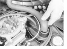
4 Disconnect the engine breather hoses at the rocker cover (see illustration .
5 Undo the four bolts securing the rocker cover to the cylinder head and lift off the shaped spreader washers.
6 Withdraw the rocker cover from the cylinder head. If it is stuck give it a tap with the palm of your hand to free it.
7 Turn the engine by means of the crankshaft pulley bolt, or by engaging top gear and pulling the car forward, until No piston is approaching TDC on the firing stroke. This can be checked by removing No 1 spark plug and feeling for compression with your fingers as the engine is turned, or by removing the distributor cap and checking the position of the rotor arm which should be pointing to the No 1 spark plug lead segment in the cap. The ignition timing marks on the pulley and timing cover must be aligned (see illustration .
8 With the engine in this position the following valves can be adjusted - counting from the timing cover end of the engine.
1 exhaust
2 inlet
3 inlet
5 exhaust
9 Now turn the engine crankshaft through one complete revolution and adjust the following remaining valves:
4 exhaust
6 inlet
7 inlet
8 exhaust
0 As each clearance is being checked, slide a feeler blade of the appropriate size, as given in the Specifications, between the end of the
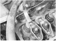
 Checking a valve clearance
Removing the breather hose from the rocker cover
valve stem and the rocker arm (see illustration) Adjust the clearance by turning the rocker arm retaining nut using a socket or ring spanner until the blade is a stiff sliding fit.
1 It is also possible to check and adjust the clearances with the engine running. This is done in the same way, but each valve is checked in turn. It will of course be necessary to refit the plug leads and No 1 spark plug if this method is adopted. To reduce oil splash place a piece of cardboard, suitably cut to shape, between the pushrod side of the rocker arms and the edge of the cylinder head.
2 After adjustment remove all traces of old gasket from the cylinder head mating face and renew the rocker cover gasket if it is cracked or perished.
3 Refit the rocker cover and secure with the retaining bolts and shaped spreader washers.
4 Refit the spark plug and plug leads, reconnect the engine breather hoses and refit the air cleaner, as described in Chapters 1 and 4.
![]() 8 Cylinder head - removal and refitting
8 Cylinder head - removal and refitting
Removal
1 Make sure that the engine is cold before commencing operations to avoid any chance of the head distorting.
2 Disconnect the battery negative terminal
3 Drain the cooling system, as described in Chapter and remove the air cleaner, as described in Chapter 4A.
4 From behind the engine, undo the two bolts securing the exhaust front pipe to the manifold. Remove the bolts and tension springs; then separate the pipe joint from the manifold.
5 Slacken the retaining clip and disconnect the radiator top hose from the thermostat housing in the water pump.
6 Slacken the alternator mounting and adjustment arm bolts, move the alternator towards the engine and slip the drivebelt off the pulleys.
7 Slacken the retaining clips and disconnect the heater hose and radiator bottom hose from the water pump.
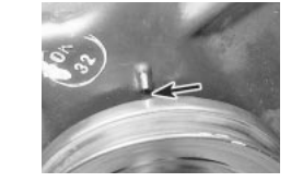

 Ignition timing marks (arrowed) in alignment
8 Disconnect the other heater hose at the cylinder head outlet after slackening the retaining clip.
9 Undo the union nut and disconnect the brake servo vacuum hose from the inlet manifold.
0 Note the location of the plug leads to aid refitting and pull them off the spark plugs. Disconnect the HT lead at the coil, undo the distributor cap retaining screws and remove the cap and leads.
1 Refer to Chapter 4A and disconnect the choke and accelerator cables from the carburettor. Detach the distributor vacuum advance pipe.
2 Disconnect the fuel hose from the carburettor and plug its end after removal.
![]() 3 Disconnect the engine breather hoses
3 Disconnect the engine breather hoses
from the rocker cover. 2A
4 Undo the three socket-headed screws securing the inlet manifold to the cylinder head. Note the spark plug lead support brackets fitted to the two end retaining bolts.
![]()
![]()
![]()
![]()
![]()
![]()
![]()
![]()
![]()
![]()
![]()
![]()
![]()
![]()
![]()
![]()
![]()
![]()
![]()
![]()
![]()
![]()
![]()
![]()
![]()
![]()
![]()
![]()
![]()
![]()
![]()
![]()
![]()
![]() 5 Lift the inlet manifold complete with carburettor from the cylinder head and recover
the gasket.
5 Lift the inlet manifold complete with carburettor from the cylinder head and recover
the gasket.
6 Undo the four bolts and shaped spreader washers and lift off the rocker cover.
7 Slacken the rocker arm retaining nuts, move the rocker arms to one side and lift out the pushrods (see illustration) Keep the pushrods in order after removal.
8 Undo the cylinder head retaining bolts, half a turn at a time in the reverse sequence to that shown in illustration 6 Unscrew the bolts fully and remove them. Obtain new bolts for use when refitting.
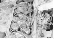
 Removing the pushrods
![]() 2A.6 OHV engine
2A.6 OHV engine
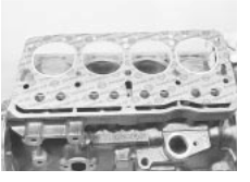
Fitting a cylinder head gasket
9 Lift the cylinder head from the block. If it is stuck, tap it free with a soft-faced mallet. Do not insert a lever into the gasket joint - you may damage the mating surfaces.
0 With the cylinder head removed, recover the gasket.
1 If the cylinder head has been removed for decarbonising or for attention to the valves or springs, reference should be made to Sections 9 and 10.
Refitting
2 Before refitting the cylinder head, ensure that the cylinder block and head mating faces are spotlessly clean and dry with all traces of old gasket removed. Use a scraper and wire brush to do this, but take care to cover the water passages and other openings with masking tape or rag to prevent dirt and carbon falling in. Remove all traces of oil and water from the bolt holes, otherwise hydraulic pressure created by the bolts being screwed in could crack the block or give inaccurate torque settings. Ensure that the bolt threads are clean and dry.
3 When all is clean, screw two guide studs into the cylinder block. These can be made from the two old cylinder head bolts by cutting off their heads and sawing a screwdriver slot in their ends.
4 Locate a new gasket in position on the block as shown (see illustration . Do not use any jointing compound on the gasket
5 Lower the cylinder head carefully into position. Screw in new bolts finger tight, remove the guide pins and screw in the two remaining bolts.
6 Tighten the cylinder head bolts in the order shown (see illustration) to the first stage specified torque. Now tighten the bolts through three further stages as given in the Specifications. No further retightening will be required.
7 Refit the pushrods, making quite sure that each one is located in its tappet.
8 Reposition the rocker arms over the ends of the pushrods and then adjust the valve clearances, as described in Section 7.
9 Place a new gasket in position and refit the inlet manifold and carburettor (see illustration .
0 Refit the rocker cover, using a new

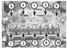
 8.26 Cylinder head bolt tightening sequence
gasket, and secure with the four bolts and spreader washers.
1 Refit the heater hoses and radiator hoses to the outlets on the water pump and cylinder head.
2 Refit the fuel hose to the carburettor, the vacuum advance pipe to the distributor and the breather hoses to the rocker cover.
3 Refit and adjust the accelerator and choke cables, as described in Chapter 4A.
4 Refit the brake servo vacuum hose to the inlet manifold.
5 Refit the distributor cap and reconnect the plug leads and coil lead.
6 Slip the drivebelt over the pulleys and adjust its tension, as described in Chapter 1.
7 Reconnect the exhaust front pipe to the manifold and tighten the bolts to compress the tension springs.
8 Refill the cooling system as described in Chapter 1, refit the air cleaner as described in Chapter 4A and connect the battery negative terminal.
![]() 9 Cylinder head - overhaul
9 Cylinder head - overhaul
1 Unscrew the rocker arm retaining
/adjustment nuts and withdraw the rocker arms from the studs. Keep them in order as they are removed.
2 To remove the valves, the springs will have to be compressed to allow the split collets to be released from the groove in the upper section of the valve stems. A valve spring compressor will therefore be necessary.
3 Locate the compressor to enable the forked end of the arm to be positioned over the valve spring collar whilst the screw part of the clamp is situated squarely on the face of the valve.
4 Screw up the clamp to compress the spring and release the pressure of the collar acting on the collets. If the collar sticks, support the head and clamp frame and give the end of the clamp a light tap with a hammer to help release it.
5 Extract the two collets and then release the tension of the clamp. Remove the clamp, withdraw the collar and spring and extract the valve. Remove the valve stem seals and the exhaust valve rotators.
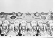
 8.29 Inlet manifold gasket in position
6 As they are released and removed, keep the valves in order so that if they are to be refitted they will be replaced in their original positions in the cylinder head. A piece of stiff card with eight holes punched in it is a sure method of keeping the valves in order.
7 Examine the head of the valves for pitting and burning, especially the heads of the exhaust valves. The valve seating should be examined at the same time. If the pitting on valve and seat is very slight, the marks can be removed by grinding the seats and valves together with coarse, and then fine, valve grinding paste.
8 Where bad pitting has occurred to the valve seats it will be necessary to recut them and fit new valves. The latter job should be entrusted to the local agent or engineering works. In practice it is very seldom that the seats are so badly worn. Normally it is the valve that is too badly worn for refitting, and the owner can easily purchase a new set of valves and match them to the seats by valve grinding.
![]()
![]()
![]()
![]()
![]()
![]()
![]()
![]()
![]()
![]()
![]()
![]()
![]()
![]()
![]()
![]()
![]()
![]()
![]()
![]()
![]()
![]()
![]()
![]()
![]()
![]()
![]()
![]() 9 Valve grinding is carried out as follows. Smear a trace of coarse carborundum paste on the seat face and apply a suction grinder tool to the valve head. With a semi-rotary motion, grind the valve head to its seat, lifting
the valve occasionally to redistribute the grinding paste. When a dull matt even surface is produced on both the valve seat and the
valve, wipe off the paste and repeat the process with fine carborundum paste, lifting
and turning the valve to redistribute the paste
as before. A light spring placed under the valve head will greatly ease this operation.
When a smooth unbroken ring of light grey
matt finish is produced, on both valve and
valve seat faces, the grinding operation is
complete.
9 Valve grinding is carried out as follows. Smear a trace of coarse carborundum paste on the seat face and apply a suction grinder tool to the valve head. With a semi-rotary motion, grind the valve head to its seat, lifting
the valve occasionally to redistribute the grinding paste. When a dull matt even surface is produced on both the valve seat and the
valve, wipe off the paste and repeat the process with fine carborundum paste, lifting
and turning the valve to redistribute the paste
as before. A light spring placed under the valve head will greatly ease this operation.
When a smooth unbroken ring of light grey
matt finish is produced, on both valve and
valve seat faces, the grinding operation is
complete.
Scrape away all carbon from the valve head and the valve stem. Carefully clean away every trace of grinding compound; take great care to leave none in the ports or in the valve guides. Clean the valves and valve seats with a paraffin-soaked rag, then with a clean rag and finally, if an air line is available, blow the valves, valve guides and valve ports clean.
Check that all valve springs are intact. If any one is broken, all should be renewed. Check the free height of the springs against new ones. If some springs are not within
![]() OHV engine 2A.7
OHV engine 2A.7
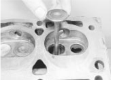
 Fitting a valve to its guide
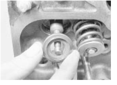
 Fitting an exhaust valve rotator
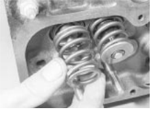
 9.18a Fit the valve spring . . .
specification, replace them all. Springs suffer from fatigue and it is a good idea to renew them even if they look serviceable.
Check that the oil supply holes in the rocker arm studs are clear.
The cylinder head can be checked for warping either by placing it on a piece of plate glass or using a straight-edge and feeler blades. Slight distortion may be corrected by having the head machined to remove metal from the mating face.
Valve guide renewal is necessary if the valve stem clearance in the guide exceeds that specified. Renewal, or reaming to accept oversize valves, should be left to a GM dealer.
Commence reassembly by lubricating a valve stem and inserting it into its guide (see illustration .
Fit the valve stem oil seal, using the protective sleeve supplied with the new seals over the valve stem to avoid damage.
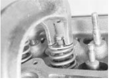
 Compress the spring and fit the collets
Lubricate the sleeve and push on the seal, ring downwards. Recover the sleeve.
7 On exhaust valves, fit the valve rotator
(see illustration
8 Fit the valve spring and collar, with the recessed part of the collar inside the spring
(see illustrations
9 Place the end of the spring compressor over the collar and valve stem and, with the screw head of the compressor over the valve head, screw up the clamp until the spring is compressed past the groove in the valve stem. Then put a little grease round the groove.
0 Place the two halves of the split collar
(collets) into the groove with the narrow ends pointing towards the spring (see illustration . The grease will hold them in the groove.
Release the clamp slowly and carefully, making sure that the collets are not dislodged from the groove. When the clamp is fully released the top edges of the collets should be in line with each other. Give the top of each spring a smart tap with a soft-faced mallet when assembly is complete to ensure that the collets are properly settled.
Repeat the above procedure for the other
7 valves.
The rocker gear can be refitted with the head either on or off the engine. The only part of the procedure to watch is that the rocker nuts must not be screwed down too far or it will not be possible to refit the pushrods.
Next put the rocker arm over the stud followed by the pivot ball (see illustrations). Make sure that the spring fits snugly round the rocker arm centre section and that the two
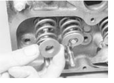
 9.18b . . . followed by the spring collar
![]() bearing surfaces of the interior of the arm and the ball face, are clean and lubricated with
bearing surfaces of the interior of the arm and the ball face, are clean and lubricated with
engine oil. 2A
Oil the stud thread and fit the nut with the self-locking collar uppermost (see illustration) Screw it down until the locking collar is on the stud.
![]()
![]()
![]()
![]()
![]()
![]()
![]()
![]()
![]()
![]()
![]()
![]()
![]()
![]()
![]()
![]()
![]()
![]()
![]()
![]()
![]()
![]()
![]()
![]()
![]()
![]()
![]() 10 Cylinder head and pistons
10 Cylinder head and pistons
![]() - decarbonising
- decarbonising
1 This can be carried out with the engine either in or out of the car. With the cylinder head removed, carefully use a wire brush and blunt scraper to clean all traces of carbon deposits from the combustion spaces and the ports. The valve head stems and valve guides should also be freed from any carbon deposits. Wash the combustion spaces and ports down with petrol and scrape the cylinder head surface free of any foreign
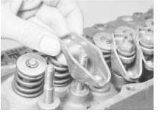
 9.24a Fitting a rocker arm . . .
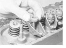
 9.24b . . . and its pivot ball
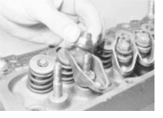
 9.25 Fit the nut with the self-locking collar uppermost
![]() 2A.8 OHV engine
2A.8 OHV engine
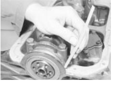
 11.7 Insert the cork strips in the main bearing
cap grooves
matter with the side of a steel rule or a similar article.
2 If the engine is installed in the car, clean the pistons and the top of the cylinder bores. If the pistons are still in the block, then it is essential that great care is taken to ensure that no carbon gets into the cylinder bores as this could scratch the cylinder walls or cause damage to the piston and rings. To ensure this does not happen, first turn the crankshaft so that two of the pistons are at the top of their bores. Stuff rag into the other two bores or seal them off with paper and masking tape. The waterways should also be covered with small pieces of masking tape to prevent particles of carbon entering the cooling system and damaging the water pump.
3 Press a little grease into the gap between the cylinder walls and the two pistons which are to be worked on. With a blunt scraper carefully scrape away the carbon from the piston crown, taking great care not to scratch the aluminium. Also scrape away the carbon from the surrounding lip of the cylinder wall. When all carbon has been removed, scrape away the grease which will now be contaminated with carbon particles, taking care not to press any into the bores. To assist prevention of carbon build-up the piston crown can be polished with a metal polish. Remove the rags or masking tape from the other two cylinders and turn the crankshaft so that the two pistons which were at the bottom are now at the top. Place rag or masking tape in the cylinders which have been decarbonised and proceed as just described. Decarbonising is now complete.
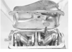
 11.9 Refitting the sump
![]()
![]()
![]()
![]()
![]()
![]()
![]()
![]()
![]()
![]()
![]()
![]()
![]()
![]()
![]()
![]()
![]()
![]()
![]()
![]()
![]()
![]()
![]()
![]()
![]()
![]()
![]()
![]()
![]()
![]()
![]() 11 Sump - removal and refitting
11 Sump - removal and refitting
Removal
1 Jack up the front of the car and securely support it on axle stands (see "Jacking and Vehicle Support").
2 Drain the engine oil into a suitable container
(Section 2) and refit the plug after draining.
3 Undo the bolts securing the flywheel cover plate and side support braces and remove the cover.
4 Undo the retaining bolts and lift away the sump. It will probably be necessary to tap the sump from side to side with a hide or plastic mallet to release the joint face.
Refitting
5 Thoroughly clean the sump in paraffin or a suitable solvent and remove all traces of external dirt and internal sludge. Scrape away all traces of old gasket from the sump and crankcase faces and ensure that they are clean and dry. Also clean the bearing cap grooves.
6 Apply a thick bead of jointing compound to the crankcase flange and at the joints of the front and rear main bearing caps
7 Position the cork side gaskets on the crankcase flanges and then insert the cork and sealing strips to the main bearing cap grooves (see illustration .
8 Apply a further bead of jointing compound to the gasket faces and to the gasket joints at the bearing caps.

 12.2a Undo the two socket-headed bolts
(arrowed) . . .
9 Refit the sump (see illustration) and secure it in place with the retaining bolts which should be progressively tightened in a diagonal sequence.
Refit the flywheel cover plate, lower the car and fill the engine with oil as described in Chapter 1.
![]()
![]()
![]()
![]()
![]()
![]()
![]()
![]()
![]()
![]()
![]()
![]()
![]()
![]()
![]()
![]()
![]()
![]()
![]()
![]()
![]()
![]()
![]()
![]()
![]()
![]()
![]()
![]()
![]()
![]()
![]() 12 Oil pump - removal and refitting
12 Oil pump - removal and refitting
Removal
1 Remove the sump. as described in Section
2 Undo the two socket-headed bolts and withdraw the pump from the crankcase (see illustrations .
Refitting
3 Refitting the pump is the reverse sequence to removal, but engage the pump shaft in the distributor driveshaft slot, and tighten the retaining bolts to the specified torque.
![]()
![]()
![]()
![]()
![]()
![]()
![]()
![]()
![]()
![]()
![]()
![]()
![]()
![]()
![]()
![]()
![]()
![]()
![]()
![]()
![]()
![]()
![]()
![]()
![]()
![]()
![]()
![]()
![]()
![]()
![]()
![]() 13 Oil pump - overhaul
13 Oil pump - overhaul
1 Remove the oil pump, as described in
Section 12.
2 Undo the two pump cover bolts and lift off the cover and oil pick-up tube. Remove the cover gasket.
3 Take out the driving gear and driven gear
(see illustrations
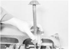
 12.2b . . . and remove the oil pump
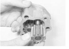
 13.3a Removing the oil pump driving gear . . .
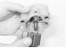
 13.3b . . . and the driven gear
![]() OHV engine 2A.9
OHV engine 2A.9
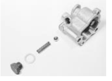
 13.4 Oil pump and pressure relief valve components
4 Undo the large nut on the side of the housing and remove the sealing washer and oil pressure relief spring and ball valve (see illustration .
5 Clean all the parts in paraffin and dry with a lint-free cloth.
6 Inspect the pump gears, housing, cover and relief valve ball for scoring, scuff marks or other signs of wear and renew the pump if these signs are evident.
7 If the pump condition is satisfactory, check the pump clearances as follows.
8 Using a feeler blade, check the backlash between the gear teeth. Place a straight-edge across the top edge of the gears and check their projection. If any of the clearances exceeds the tolerances given in the Specifications, renew the pump (see illustration .
9 If the clearances are satisfactory, refit the
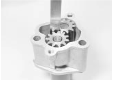
 13.8 Check the pump gear teeth backlash
relief valve assembly and assemble the pump gears. Fill the pump with oil and refit the cover using a new gasket. Tighten the cover securing bolts and refit the pump.
![]() 14 Timing gear components - removal and refitting
14 Timing gear components - removal and refitting
Removal
1 For greater access remove the front right-hand wheel trim and slacken the wheel bolts. Jack up the front of the car, support it securely on axle stands (see "Jacking and Vehicle Support") and remove the roadwheel.
2 Undo the four retaining bolts and remove the clutch access plate at the base of the bellhousing (see illustration .
3 Slacken the alternator mounting and adjustment arm bolts, move the alternators
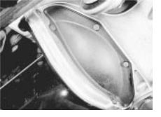
 14.2 Clutch access plate
towards the engine and slip the drivebelt off the pulleys.
![]()
![]()
![]()
![]()
![]()
![]()
![]()
![]()
![]()
![]()
![]()
![]()
![]()
![]()
![]()
![]()
![]()
![]()
![]()
![]()
![]()
![]()
![]()
![]()
![]()
![]()
![]()
![]()
![]()
![]()
![]()
![]()
![]()
![]()
![]() 4 Lock the flywheel by wedging a screwdriver
between the ring gear teeth and the side of
the bellhousing.
4 Lock the flywheel by wedging a screwdriver
between the ring gear teeth and the side of
the bellhousing.
5 Using a socket or spanner undo the crankshaft pulley retaining bolt and withdraw the pulley.
6 Undo the bolts securing the timing cover to the front of the engine and lift off the cover.
7 Withdraw the oil slinger from the crankshaft, noting which way round it is fitted
(see illustration
![]() 8 Temporarily refit the pulley and turn the crankshaft until the crankshaft sprocket
keyway is uppermost and the timing marks on
the two sprockets are in alignment
(see illustration . Remove the pulley.
8 Temporarily refit the pulley and turn the crankshaft until the crankshaft sprocket
keyway is uppermost and the timing marks on
the two sprockets are in alignment
(see illustration . Remove the pulley.
9 Undo the two retaining bolts and remove 2A
the timing chain tensioner. One of two types of tensioner may be fitted: simple spring-operated, or oil pressure assisted. With the oil pressure assisted type, restrain the thrust pad to prevent premature ejection of the tensioner components (see illustration .
Undo the camshaft sprocket retaining bolt and remove the bolt and washer (see illustration . Place a screwdriver through one of the sprocket holes and in contact with the camshaft retaining plate behind the sprocket to stop it turning as the bolt is undone.
Withdraw the camshaft sprocket and crankshaft sprocket from their respective locations, using a screwdriver as a lever if
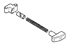

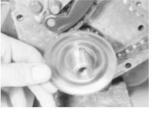

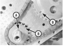
 14.7 Crankshaft oil slinger 14.8 Crankshaft sprocket keyway (A) and sprocket timing marks (B)
necessary, then remove the sprockets complete with chain (see illustration .
Thoroughly clean all the components in
14.9 Timing chain tensioner - oil pressure assisted type
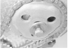
 14.10 Camshaft sprocket retaining bolt and washer
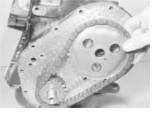
 14.11 Removing the sprockets and timing chain
![]() 2A.10 OHV engine
2A.10 OHV engine
 14.13 Using a drift to remove the timing cover oil
seal
paraffin and dry them with a lint-free cloth. Remove all traces of old gasket from the faces of the timing cover and engine.
Refitting
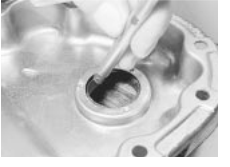
To renew the oil seal in the timing cover, place the cover outer face downwards over two blocks of wood and drive out the old seal and holder using a hammer and drift (see illustration .
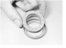
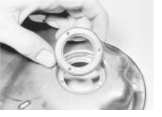
Place the new seal (which must have been soaked in engine oil for 24 hours) in the holder and then tap the holder into the cover using a block of wood (see illustrations) The seal holder must be fitted flush with the outer edge of the timing cover.
5 Commence reassembly by engaging the chain around the crankshaft sprocket.
6 Engage the camshaft sprocket within the loop of the chain so that it can be fitted to the
 14.19a Fit the tensioner lower bolt . . .
 14.14a Fit the new seal to the holder
camshaft and will have its timing mark in alignment with the one on the crankshaft sprocket. Adjust the camshaft sprocket as necessary within the chain loop to achieve this.
7 Fit the sprocket to the camshaft, screw in the bolt and washer and tighten the bolt while holding the sprocket with a screwdriver, as was done during removal.
8 Refit the timing chain tensioner. With the oil pressure assisted type, compress the thrust pad by hand, secure the tensioner and release the thrust pad.
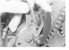
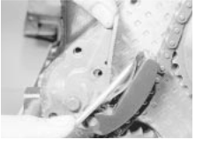
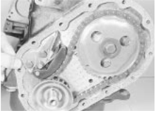
9 To refit the spring-operated chain tensioner, place the tensioner in position and fit the lower retaining bolt finger tight. Move the spring blade away from the tensioner body with a screwdriver, pivot the tensioner into position and fit the upper retaining bolt, then release the springs and tighten both bolts (see illustrations .
0 Position the oil slinger over the crankshaft and place a new gasket on the front of the engine (see illustration) Apply jointing compound to both sides of the gasket.
1 Refit the cover and the retaining bolts, but only screw the bolts in two or three turns (see illustration . Position the crankshaft pulley on the crankshaft to centralise the cover and then tighten the bolts progressively in a diagonal sequence.
2 Refit the pulley retaining bolt and tighten to the specified torque.
3 Refit the drivebelt and adjust its tension, as described in Chapter 1.
4 Refit the roadwheel and lower the car to the ground. Tighten the wheel bolts.
 14.14b . . . and refit the holder and seal to the
timing cover
15 Pistons and connecting rods
![]()
![]()
![]()
![]()
![]()
![]()
![]()
![]()
![]()
![]()
![]()
![]()
![]()
![]()
![]()
![]()
![]()
![]()
![]()
![]()
![]()
![]()
![]()
![]()
![]()
![]()
![]()
![]()
![]()
![]()
![]()
![]()
![]()
![]()
![]()
![]()
![]()
![]()
![]()
![]() - removal and refitting
- removal and refitting
Removal
1 Remove the cylinder head, the sump and the oil pump, as described in earlier Sections.
2 The connecting rod big-end caps and rods may not be marked numerically for location when new and therefore they must be inspected for identification marks before dismantling. If no marks are evident, punch, scribe or file identification marks on the caps and rods starting with No 1 at the timing cover end. Mark them all on the same side to avoid confusion during reassembly. If they have already been marked then this will not, of course, be necessary.
3 Undo and remove the big-end cap retaining bolts and keep them in order for correct refitting.
4 Detach the big-end bearing caps. If stuck, lightly tap them free using a soft-faced mallet.
5 To remove the bearing shells for inspection and/or renewal, press the bearing end opposite the groove in both connecting rod and bearing cap and the shells will slide out. Again keep the shells in order of removal.
6 The piston rod assemblies are removed through the top of each cylinder bore, being pushed upwards from underneath using a wooden hammer handle which is pushed against the connecting rod. Rotate the crankshaft accordingly to gain suitable access to each rod assembly. Note that, if there is a pronounced wear ridge at the top of the
 14.19b . . . then push back the spring, pivot the
tensioner and fit the upper bolt
 14.20 Fitting a new timing cover gasket
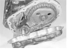
 14.21 Refitting the timing cover
![]() OHV engine 2A.11
OHV engine 2A.11
Refitting
5 Refitting is the reverse sequence to removal. Tighten the flywheel retaining bolts to the specified torque.
![]()
![]()
![]()
![]()
![]()
![]()
![]()
![]()
![]()
![]()
![]()
![]()
![]()
![]()
![]()
![]()
![]()
![]()
![]()
![]()
 17 Engine/transmission mountings - removal and refitting
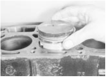
 15.11 Offering the piston to the bore
cylinder bore, there is a risk of piston ring damage unless the ridge is first removed using a ridge reaming tool, or scraper.
7 The pistons should not be separated from their connecting rods unless they or the gudgeon pins are to be renewed. The gudgeon pin is a press fit and special tools are required for removing and installation. This task should therefore be entrusted to your local agent or automotive machine shop.
8 If for any reason the pistons are separated from their rods, mark them numerically on the same side as the rod markings to ensure correct refitting.
Refitting
9 If new pistons or piston rings are being fitted to the old bores, it is essential to roughen the cylinder bore walls slightly with medium grit emery cloth to allow the rings to bed in. Do this with a circular up-and-down action to produce a criss-cross pattern on the cylinder bore walls. Make sure that the bearing journal on the crankshaft is protected with masking tape during this operation. Thoroughly clean the bores with a paraffin-soaked rag and dry with a lint-free cloth Remove the tape from the crankshaft journals and clean them also.
0 Commence reassembly by lubricating the cylinder bores and crankshaft journals.
Space the piston rings around the pistons so that their end gaps are apart. In the case of the oil scraper ring, offset the gaps in the upper and lower rails by 25 to 50 mm to right and left of the end gap of the central section. Offer a piston/connecting rod
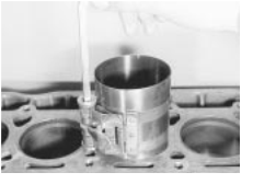
 15.12 Piston ring compressor fitted
assembly to its bore, making sure that it is the right way round (see illustration .
2 Oil the piston and rings, then fit a piston ring compressor to the piston and tighten it to compress the rings (see illustration .
Gently tap the piston through the ring compressor and into its bore using the hammer handle. Guide the connecting rod near to its crankshaft journal and then fit the bearing shell upper half.
Ease the connecting rod onto the journal, fit the lower shell to the cap and fit the cap to the rod (see illustration . Refit and tighten the retaining bolts to the specified torque (see illustration .
5 Repeat the sequence described for the remaining three piston/ connecting rods.
6 Refit the cylinder head, oil pump and sump, as described in earlier Sections.
![]()
![]()
![]()
![]()
![]()
![]()
![]()
![]()
![]()
![]()
![]()
![]()
![]()
![]()
![]()
![]()
![]()
![]()
![]()
![]()
![]()
![]()
![]()
![]()
![]()
![]()
![]()
![]()
![]()
![]() 16 Flywheel - removal and refitting
16 Flywheel - removal and refitting
Removal
1 Remove the clutch assembly and the release bearing, as described in Chapter 6.
2 Undo the three bolts and remove the release bearing guide tube.
3 Mark the position of the flywheel in relation to the crankshaft mounting flange or pulley.
4 Wedge a screwdriver between the ring gear teeth and transmission casing and then undo the socket-headed retaining bolts using a multi-tooth key or socket bit (see illustration . Remove the bolts and withdraw the flywheel.
Removal
1 The engine/transmission assembly is supported in a triangular arrangement of three mountings: one on the right-hand side supporting the engine, one on the left-hand side supporting the transmission and a third centrally sited mount supporting the complete assembly at the rear.
2 To remove either of the front mountings position a jack under the engine or transmission adjacent to the mounting and just take the weight of the engine or transmission.
3 Undo the bolts securing the support bracket to the engine or gearbox and the bolts securing the mounting to the bodyframe. Lift off the bracket and remove the relevant mounting.
4 To remove the rear mounting jack up the front of the car and support it on axle stands
(see "Jacking and Vehicle Support").
![]() Support the engine/transmission assembly
Support the engine/transmission assembly
under the differential cover plate using a jack 2A
and interposed block of wood.
Undo the two bolts securing the mounting to the underbody and the through-bolt and nut securing the mounting to the support bracket. Slide the mounting rearwards out of the bracket and remove it from under the car. Refitting
In all cases refitting is the reverse sequence to removal, but tighten the retaining bolts to the specified torque. Where thread locking compound was evident on the old bolts, clean out the bolt holes using a tap (or an old bolt with a slot cut in its threads); clean the bolt threads and apply thread locking compound.
If there is an arrow stamped on the rear mounting, it should point to the front when the mounting is fitted.
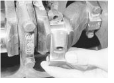
 15.14a Fitting a big-end
bearing cap
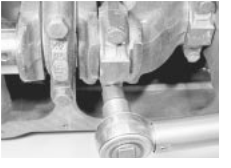
 15.14b Tightening a big-end bearing cap bolt
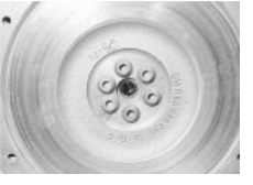
 Flywheel retaining bolts are socket-headed
![]() 2A.12 OHV engine
2A.12 OHV engine
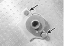
 18.4a Camshaft retaining
plate bolts
(arrowed)
![]() Camshaft and tappets - removal and refitting
Camshaft and tappets - removal and refitting
Removal
Remove the engine from the car, as described in Section 23, and then remove the sump and timing gear components, as described in earlier Sections.
2 If the cylinder head is still in place, slacken the rocker arm nuts, move the rocker arms to one side and lift out the pushrods, keeping them in order.
3 Invert the engine or, if the cylinder head is still in place, lay the engine on its side.
4 Undo the two bolts securing the camshaft retaining plate in position and lift off the plate
(see illustrations The engine front plate should also be removed as all the bolts securing it in place have now been undone.
5 Carefully withdraw the camshaft from the cylinder block, taking care not to scratch the bearing journals with the sharp edges of the cam lobes (see illustration .
6 From within the crankcase withdraw each tappet from its bore and keep them in order for refitting (see illustration .
Refitting
7 Scrape away all traces of old gasket from the engine front plate and cylinder block. Make sure that both mating faces are clean and dry.
Lubricate the tappet bores in the crankcase and insert each tappet into its respective bore.
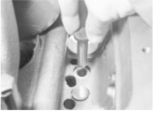
 Removing a tappet
![]()
![]()
![]()
![]()
![]()
![]()
![]()
![]()
![]()
![]()
![]()
![]()
![]()
![]()
![]()
![]()
![]()
![]()
![]()
![]()
![]()
![]()
![]()
![]()
![]()
![]()
![]()
![]()
![]()
![]()
![]()
![]()
![]()
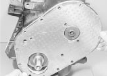
 18.4b Removing the engine front plate
9 Lubricate the camshaft bearing journals and carefully insert the camshaft.
0 Place a new gasket in position and then locate the front plate, patterned side outward, over the gasket (see illustration . Temporarily refit two or three of the timing cover bolts to act as alignment guides, but only tighten them finger tight.
1 Now position the camshaft retaining plate with its forks located into the groove in the boss on the end of the camshaft. Note that the fork section faces upwards. Secure the retaining plate with the two bolts.
2 Check that the camshaft is free to turn.
3 Refit the timing gear components and the sump, as described in earlier Sections. If the cylinder head is in place, refit the pushrods and adjust the valve clearances.
4 Refit the engine to the car.
![]()
![]()
![]()
![]()
![]()
![]()
![]()
![]()
![]()
![]()
![]()
![]()
![]()
![]()
![]()
![]()
![]()
![]()
![]()
![]()
![]()
![]()
![]()
![]()
![]()
![]()
![]()
![]()
![]()
![]()
![]()
![]()
![]()
![]()
![]() 19 Crankshaft rear oil seal - removal
and refitting
19 Crankshaft rear oil seal - removal
and refitting
Removal
1 Remove the engine from the car, as described in Section 23, and then remove the sump and flywheel, as described in earlier Sections.
2 Slacken the rear main bearing cap bolts slightly and withdraw the oil seal from its location.
Refitting
3 Lubricate the lips of a new oil seal and carefully ease it over the crankshaft boss and
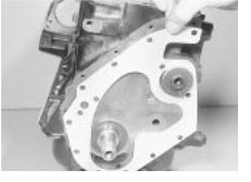
 Fitting a new front plate gasket
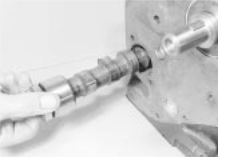
 Removing the camshaft
into position. Make sure that the seal is fully entered into its location so that its outer face is flush with the edge of the bearing cap and cylinder block.
4 Apply jointing compound to the contact edges of the main bearing cap and then tighten the retaining bolts to the specified torque.
5 Refit the sump and flywheel, as described earlier, and then refit the engine to the car, as described in Section 23.
![]()
![]()
![]()
![]()
![]()
![]()
![]()
![]()
![]()
![]()
![]()
![]()
![]()
![]()
![]()
![]()
![]()
![]()
![]()
![]()
![]()
![]()
![]()
![]()
![]()
![]()
![]()
![]()
![]()
![]()
![]()
![]()
![]()
![]()
![]()
![]()
![]()
![]()
![]()
![]()
![]() 20 Crankshaft
and main bearings
20 Crankshaft
and main bearings
![]() removal and refitting
removal and refitting
Removal
1 With the engine removed from the car, as described in Section and all the components removed from it, as described in earlier Sections, the crankshaft can be removed as follows.
2 Invert the engine. The three main bearing caps are all different so note their locations.
3 Undo the retaining bolts and remove the bearing caps.
4 Lift out the crankshaft and remove the rear oil seal from the crankshaft boss.
5 Remove the main bearing shells from the crankcase and bearing caps and identify them for location.
Refitting
Commence reassembly as follows.
7 Ensure that the crankcase and crankshaft are thoroughly clean and that all oilways are clear. If possible blow the drillings out with compressed air, and then inject clean engine oil through them to ensure that they are clear.
Avoid using old bearing shells; wipe the shell seats in the crankcase clean and then fit the upper halves of the main bearing shells into their seats.
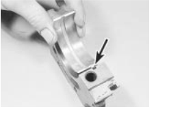
9 Note that there is a tab on the back of each bearing which engages with a groove in the shell seating (in both crankcase and bearing cap) (see illustration .
0 Wipe away all traces of protective grease on the new shells.
1 The central bearing shell also takes up the crankshaft endfloat. Note that the half-shells fitted to the cylinder block all have oil duct
![]() OHV engine 2A.13
OHV engine 2A.13
Bearing shell tab engages with groove (arrowed)
holes, while only the centre main bearing cap half-shells has an oil duct hole.
2 When the shells are fully located in the crankcase and bearing caps, lubricate them with clean engine oil (see illustration .
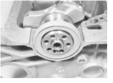
3 Carefully install the crankshaft into position in the crankcase (see illustration .
4 Lubricate the crankshaft main bearing journals and then refit the centre main bearing cap (see illustration) Tighten the retaining bolts to the specified torque wrench setting.
5 Locate the new oil seal onto the rear end of the crankshaft, and apply jointing compound to the block mating flange. Also fill the grooves on both sides of the rear main bearing cap with sealant (see illustrations .
6 Fit the rear main bearing cap and tighten the retaining bolts to the specified torque (see illustration .
7 Fit the front main bearing cap, but before
 20.15a Crankshaft rear oil seal
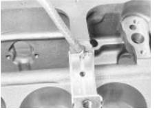

 Lubricate the bearing shells
fitting the retaining bolts smear them with jointing compound and then tighten to the specified torque wrench setting. Check that the bearing cap is exactly flush with the end face of the crankcase as it is tightened.
8 Now rotate the crankshaft and check that it turns freely, and shows no signs of binding or tight spots. Check that the crankshaft endfloat is within the limits specified using a feeler blade as shown (see illustration) No provision is made for adjusting crankshaft endfloat; if it is outside the specified limits, the most likely reasons are wear or incorrect regrinding (assuming that the correct shells have been fitted).
![]() 21 Engine components - examination and renovation
21 Engine components - examination and renovation
Crankshaft
1 Examine the crankpin and main journal surfaces for signs of scoring or scratches, and check the ovality and taper of the crankpins and main journals. If the bearing surface dimensions do not fall within the tolerance ranges given in the Specifications at the beginning of this Chapter, the crankpins and/or main journals will have to be reground.
2 Big-end and crankpin wear is accompanied by distinct metallic knocking, particularly noticed when the engine is pulling from low revs, and some loss of oil pressure.
3 Main bearing and main journal wear is accompanied by severe engine vibration rumble - getting progressively worse as
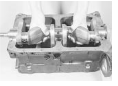
 20.13 Fitting the crankshaft
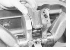
 20.14 Fitting the centre main bearing cap
![]() engine revs increase - and again by loss of oil pressure.
engine revs increase - and again by loss of oil pressure.
4 If the crankshaft requires regrinding take it
to an engine reconditioning specialist, who 2A
![]()
![]()
![]()
![]()
![]()
![]()
![]()
![]()
![]()
![]()
![]()
![]()
![]()
![]() will machine it for you and supply the correct
undersize bearing shells.
will machine it for you and supply the correct
undersize bearing shells.
5 On some engines, the crankshaft journal diameters are machined undersize in production to allow for greater manufacturing tolerances.
Big-end and main bearing shells
6 Inspect the big-end and main bearing shells for signs of general wear, scoring, pitting and scratches. The bearings should be matt grey in colour. With lead-indium bearings, should a trace of copper colour be noticed, the bearings are badly worn as the lead bearing material has worn away to expose the indium underlay. Renew the bearings if they are in this condition or if there are any signs of scoring or pitting.
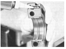
 20.15b Fill the rear main bearing cap grooves with
sealant
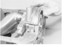
 20.16 Fitting the rear main bearing cap
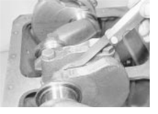
 20.18 Checking the crankshaft endfloat
2A.14 OHV engine


![]()
![]()
![]()
![]()
![]()
![]()
![]()
![]()
![]()
![]()
![]()
![]()
![]()
![]()
![]()
![]()
![]()
![]()
![]()
![]()
![]()
![]()
![]() You are strongly advised to renew the bearings - regardless of
their condition
You are strongly advised to renew the bearings - regardless of
their condition
- at time of major overhaul. Refitting used bearings is a false economy.
7 The undersizes available are designed to correspond with crankshaft regrind sizes. The bearings are in fact, slightly more than the stated undersize as running clearances have been allowed for during their manufacture. Cylinder bores
The cylinder bores must be examined for taper, ovality, scoring and scratches. Start by carefully examining the top of the cylinder bores. If they are at all worn a very slight ridge will be found on the thrust side. This marks the top of the piston travel. The owner will have a good indication of the bore wear prior to dismantling the engine, or removing the cylinder head. Excessive oil consumption accompanied by blue smoke from the exhaust can be caused by worn cylinder bores and piston rings.
9 Measure the bore diameter across the block and just below any ridge. This can be done with an internal micrometer or a dial gauge. Compare this with the diameter of the bottom of the bore, which is not subject to wear. If no measuring instruments are available, use a piston from which the rings have been removed and measure the gap between it and the cylinder wall with a feeler blade.
0 Refer to the Specifications. If the cylinder wear exceeds the permitted tolerances then the cylinders will need reboring.
1 If the cylinders have already been bored out to their maximum it may be possible to have liners fitted. This situation will not often be encountered.
Connecting rods
2 Examine the mating faces of the big-end caps to see if they have ever been filed in a mistaken attempt to take up wear. If so, the offending rods must be renewed.
3 Check the alignment of the rods visually, and if all is not well, take the rods to your local agent for checking on a special jig.
Pistons and piston rings
4 If the pistons and/or rings are to be re-used, remove the rings from the pistons. Three strips of tin or mm feeler blades should be prepared and the top ring then sprung open just sufficiently to allow them to be slipped behind the ring. The ring can then be slid off the piston upwards without scoring or scratching the piston lands.
5 Repeat the process for the second and third rings.
6 Mark the rings or keep them in order so they may be refitted in their original locations.
7 Inspect the pistons to ensure that they are
suitable for re-use. Check for cracks, damage to the piston ring grooves and lands, and scores or signs of picking-up the piston walls.
8 Clean the ring grooves using a piece of old piston ring ground to a suitable width and scrape the deposits out of the grooves, taking care not to remove any metal or score the piston lands. Protect your fingers - piston rings are sharp.
9 Check the rings in their respective bores. Press the ring down to the unworn lower section of the bore (use a piston to do this, and keep the ring square in the bore). Measure the ring end gap and check that it is within the tolerance allowed (see Specifications). Also check the ring's side clearance in its groove. If these measurements exceed the specified tolerances the rings will have to be renewed, and if the ring grooves in the pistons are worn new pistons may be needed.
0 Proprietary piston rings are available which are reputed to reduce oil consumption due to bore wear without the expense of a rebore. Depending on the degree of wear, the improvement produced by fitting such rings may be short-lived.
1 If new rings (or pistons and rings) are to be fitted to an existing bore the top ring must be stepped to clear the wear ridge at the top of the bore, or the bore must be de-ridged.
2 Check the clearance and end gap of any new rings, as described in paragraph 19. If a ring is slightly tight in its groove it may be rubbed down using an oilstone or a sheet of carborundum paper laid on a sheet of glass. If the end gap is inadequate the ring can be carefully ground until the specified clearance is achieved.
3 If new pistons are to be installed they will be selected from the grades available (see Specifications), after measuring the bores as described in paragraph Normally the appropriate oversize pistons are supplied by the repairer when the block is rebored.
4 Removing and refitting pistons on the connecting rod is a job for your dealer or specialist repairer. Press equipment and a means of accurately heating the connecting rod will be required for removal and insertion of the gudgeon pin.
Camshaft and bearings
5 With the camshaft removed, examine the bearings for signs of obvious wear and pitting. If there are signs, then the three bearings will need renewal. This is not a common requirement and to have to do so is indicative of severe engine neglect at some time. As special tools are necessary to do this work properly, it is recommended that it is done by your dealer. Check that the bearings are located properly so that the oilways from the bearing housings are not obstructed.
6 The camshaft itself should show no marks on either the bearing journals or the profiles. If it does, it should be renewed.
7 Examine the skew gear for signs of wear
![]() or damage. If this is badly worn it will mean renewing the camshaft.
or damage. If this is badly worn it will mean renewing the camshaft.
8 The thrust plate (which also acts as the locating plate) should not be ridged or worn in any way. If it is, renew it.
Timing chain sprockets and tensioner
9 Examine the teeth of both sprockets for wear. Each tooth is the shape of an inverted V and if the driving (or driven) side is concave in shape, the tooth is worn and the sprocket should be renewed. The chain should also be renewed if the sprocket teeth are worn. It is sensible practice to renew the chain anyway.
0 Inspect the chain tensioner, which is automatic in operation. The most important item to check is the shoe which wears against the chain. If it is obviously worn, scratched or damaged in any way, then it must be renewed. Check the spring for signs of wear and renew the unit if generally worn or defective, or when a new chain is being fitted. Valve rocker arms, pushrods and tappets
1 Each rocker arm has three wearing surfaces, namely the pushrod recess, the valve stem contact, and the centre pivot recess. If any of these surfaces appear severely grooved or worn the arm should be renewed. If only the valve stem contact area is worn it is possible to clean it up with a fine file.
2 If the rocker ball is pitted, or has flats in it, this should also be renewed.
3 The nut on the rocker stud is a self-locking type. If it has been removed or adjusted many times, the self-locking ring may have become ineffective and the nut may be slack enough to turn involuntarily and alter the tappet clearance.
4 The rocker studs should be examined to ensure that the threads are undamaged and that the oil delivery hole in the side of the stud at the base of the thread is clear. Place a straight-edge along the top of all the studs to ensure that none is standing higher than the rest. If any are, it means that they have pulled out of the head some distance. They should be removed and replaced with an oversize stud. As this involves reaming out the stud hole to an exact size to provide an interference fit for the replacement stud, you should seek professional advice and assistance to ensure that the new oversize stud is securely fitted at the correct angle.
5 Any pushrods which are bent should be renewed. On no account attempt to straighten them. They are easily checked by rolling over a perfectly flat surface such as a sheet of glass.
6 Examine the bearing surfaces of the tappets which lie on the camshaft. Any indentation in these surfaces or any cracks indicate serious wear and the tappets should be renewed. Thoroughly clean them out, removing all traces of sludge. It is most unlikely that the sides of the tappets will prove
OHV engine 2A.15
![]() worn but, if they are a very loose fit in their bores and can readily be rocked, they should
be exchanged for new ones. It is very unusual to find any wear in the tappets, and any wear present is likely to occur at very high mileages, or in cases or neglect. If the tappets are worn, examine the camshaft carefully as
well!.
worn but, if they are a very loose fit in their bores and can readily be rocked, they should
be exchanged for new ones. It is very unusual to find any wear in the tappets, and any wear present is likely to occur at very high mileages, or in cases or neglect. If the tappets are worn, examine the camshaft carefully as
well!.
Flywheel
7 If the teeth on the flywheel starter ring are badly worn, or if some are missing, then it will be necessary to remove the ring and fit a new one.
8 Either split the ring with a cold chisel after making a cut with a hacksaw blade between two teeth, or use a soft-headed hammer (not steel) to knock the ring off, striking it evenly and alternately at equally spaced points. Take great care not to damage the flywheel during this process, and protect your eyes from flying fragments.
9 Clean and polish with emery cloth four evenly spaced areas on the outside face of the new starter ring.
0 Heat the ring evenly with a flame until the polished portions turn dark blue. Alternatively heat the ring in a bath of oil to a temperature of 0°C. (If a naked flame is used take adequate fire precautions.) Hold the ring at this temperature for five minutes and then quickly fit it to the flywheel, so the chamfered portion of the teeth faces the gearbox side of the flywheel. Wipe all oil off the ring before fitting it.
1 The ring should be tapped gently down onto its register and left to cool naturally when the contraction of the metal on cooling will ensure that it is a secure and permanent fit. Great care must be taken not to overheat the ring, indicated by it turning light metallic blue. If this happens the temper of the ring will be lost.
2 If the driven plate contact surface of the flywheel is scored or on close inspection shows evidence of small hair cracks, caused by overheating, it may be possible to have the flywheel surface ground provided the overall thickness of the flywheel is not reduced too much. Consult a specialist engine repairer and if it is not possible, renew the flywheel complete.
3 If the needle bearing in the centre of the crankshaft flange is worn, fill it with grease and tap in a close-fitting rod. Hydraulic pressure will remove it. Tap the new bearing into position and apply a little grease.
![]() 22 Engine lubrication system - general description
22 Engine lubrication system - general description
The engine lubrication system is quite conventional. A gear type oil pump draws oil up from the sump, via the suction pipe and strainer, and pumps the oil under pressure in the cartridge oil filter. From the oil filter the oil
flows into galleries drilled in the engine block to feed the main bearings on the crankshaft and the moving components of the cylinder head. Oil is bled from the main bearing journals in the crankshaft to supply the big-end bearings.
Therefore, the bearings which receive pressure lubrication are the main crankshaft bearings, the big-end bearings, the camshaft bearings, and the rocker arms.
The remaining moving parts receive oil by splash or drip feed and these include the timing chain and associated items, the distributor and fuel pump drive, the tappets, the valve stems and to a certain extent the pistons.
The lubrication system incorporates two safeguards. The first is a pressure operated ball valve situated in the gallery between the oil and oil filter. This is in effect a filter bypass valve and allows oil to pass directly into the engine block gallery, downstream of the filter, when the filter is clogged up and resists the flow of oil.
The second system is an oil pressure relief valve, located in the oil pump casing, which controls the oil pressure to the specified maximum.
![]()
![]()
![]()
![]()
![]()
![]()
![]()
![]()
![]()
![]()
![]()
![]()
![]()
![]()
![]()
![]()
![]()
![]()
![]()
![]()
![]()
![]()
![]()
![]()
![]()
![]()
![]() 23 Engine - removal and refitting
23 Engine - removal and refitting
Removal
1 The makers recommend that the engine be removed from above, leaving the gearbox in the vehicle.
2 Disconnect the battery positive and negative terminals. Remove the bonnet
(Chapter 11).
3 Remove the air cleaner (Chapter 4A).
4 Drain the cooling system (Chapter . Disconnect the coolant hoses from the water pump, thermostat housing and cylinder head. not forgetting the heater hoses.
5 Disconnect and plug the fuel pump feed hose, and (when fitted) the fuel return hose. Be prepared for fuel spillage.
Disconnect the throttle and choke cables from the carburettor (Chapter 4A).
7 Disconnect the brake servo vacuum hose, either from the servo or from the manifold. Secure the hose so that it will not be damaged.
Release the electrical connectors for the oil pressure switch and the coil LT terminals. Unplug the coil-to-distributor HT lead at the distributor cap.
9 Disconnect the engine wiring harness multi-plug, pressing its locking device to release it.
0 Withdraw the clutch input shaft (see
Chapter 6).
1 Unbolt the exhaust downpipe from the manifold.
2 Remove the three flywheel cover plate
bolts, which are accessible from below.
3 Secure the lifting tackle to the engine and take its weight.
4 Support the gearbox with a jack or blocks, then remove the right-hand mounting completely.
5 Remove the remaining engine-to-clutch housing bolts.
6 Make sure that no attachments have been overlooked, then carefully draw the engine away from the clutch housing and lift it out. Refitting
7 Refit in the reverse order to removal, referring to the appropriate Chapters for guidance if necessary. If the clutch has been disturbed, make sure that the driven plate is centralised (Chapter 6), otherwise it will not be possible to refit the clutch input shaft.
8 Refer to Section before starting the engine.
![]() 24 Engine - initial start-up after overhaul
24 Engine - initial start-up after overhaul
Make sure the battery is fully charged and that all lubricants, coolant and fuel are replenished.
![]() 2 If the fuel system has been dismantled it will require several revolutions of the engine on
the starter motor to pump the petrol up to the
carburettor.
2 If the fuel system has been dismantled it will require several revolutions of the engine on
the starter motor to pump the petrol up to the
carburettor.
3 As soon as the engine fires and runs, keep
it going at a fast tickover only (no faster) and 2A
bring it up to the normal working temperature.
4 As the engine warms up there will be odd smells and some smoke from parts getting hot and burning off oil deposits. The signs to look for are leaks of water or oil which will be obvious if serious. Check also the exhaust pipe and manifold connections, as these do not always 'find' their exact gastight position until the warmth and vibration have acted on them, and it is almost certain that they will need tightening further. This should be done, of course, with the engine stopped.
5 When normal running temperature has been reached adjust the engine idling speed, as described in Chapter and check the valve clearances, as described in Section 7 of this Chapter.
6 Stop the engine and wait a few minutes to see if any lubricant or coolant is dripping out when the engine is stationary.
Road test the car to check that the timing is correct and that the engine is giving the necessary smoothness and power. Do not race the engine - if new bearings and/or pistons have been fitted it should be treated as a new engine and run in at a reduced speed for the first 500 miles (800 km).
8 If many new internal components have been fitted, it will be beneficial to change the engine oil and oil filter after the first 1000 miles
(1600 km).
|