SERVICE MANUAL
SK 1 - 08
DENTAL PATIENT CHAIR
INTRODUCTION
The dental patient chair SK1-08 (hereinafter referred to as the chair) is a part of the equipment of dental outpatients and serves for placing and positioning of the patient during treatment. The design of the chair enables the carrying of additional devices.
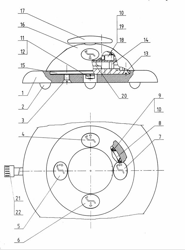
Product Description (Fig. 1)
The base with a bracket (1) covered with a base housing (2) and energoblock housing (3) has a movable pedal actuator (4) taken out in the rear side. The arms of parallelogram (5) are fixed in the bracket using pins. The drive unit (6) ensuring the vertical movement of the chair top is fixed by a bottom eyelet on the base and by the upper eyelet in the carrying arm. There is a panel of electronic control of the chair and source block (7) at the side of the base bracket. There is a main switch (8) in the right side board of the bottom energoblock housing (3) and the chair is connected to the electric mains using the movable mains cord (9) through it. The entire area of the energoblock is covered with top housing (3a) that is secured with two screws with caps. Base housing is equipped with rubber laths (18) from the lateral sides.
If the chair is used with sets of SMILE type, there is an energoblock located in the energoblock housing.
The coupling between the arms of parallelogram and the chair top is formed by the upper case covered by the upper case housing (13). Top beam (11), covered with a chair top housing (10) is fixed using pins and tilting system to the upper case, it enables the enlargement of the seat tilting from horizontal level. In the front side of the top beam, there is fixed drive unit (12) for tilting the backrest down to anti-shock position. Armrest (14) is firmly fixed on the left profile of the beam. On the rear side of the top housing, there is a display (23) enabling the program control of the chair.
In the version with two armrests, there is armrest (21) fixed on the right beam profile and it can be tilted backwards.
In the version with electric armrest shift, it shall be moved automatically to front centre when recalling programs 2 - 4 and to the rear centre when recalling program 1.
The backrest (15) is fixed on the tilting device of the rest. There is a mechanism of the vertical adjustment of headrest controlled by a lever (20) in the upper part of the rest. Headrest (16) can be tilted around two pins. The adjusted position shall be secured by a joint mechanism controlled by a button (17). If the chair is equipped with 939h72j an electric headrest shift, the required position of the headrest shall be achieved by controlling the lever located on the rear side of the rest. The seat of a poloeuforian (19) type is fixed onto the top beam with two hooks and winged nut. The seat is covered with the seat bottom cover (22) from the bottom side.
The chair is equipped with 939h72j safety switches, namely for backrest and for downward movement of the chair.
A 1

Fig. 1
A - 2
Base
Base housing
Energoblock housing bottom
3a. Energoblock housing top
Pedal actuator
Carrying arm
Uplift drive unit
Source block
Main switch
Mains cord
Top housing
Top beam
Backrest drive unit
Top case housing
Armrest - left
Backrest
Headrest
Headrest button
Covering rubber
Seat
Control lever
Armrest right
Bottom seat cover
Display
Bottom arm cover
A - 3
SPECIFICATION
The chair meets standard STN EN ISO 6875 (dental patient chair)
Rated voltage 230V~ (110V~) ± 10 %
Rated frequency (50 - 60) Hz ± 2 %
Maximal power consumption at 50 Hz 300 VA
Level of protection against electric shock B ![]()
Type of protection against electric shock I
Coverage level IP 31
Chair weight
The chair is designed for loading with the weight of 200 ±
During the operation of a chair which top is loaded with the weight of
For the overall dimensions see Fig. No. 2.
The minimal position of the seat is 460 ±
The maximal position of the seat is 890 ±
The basic position of the backrest is 24o ± 3o from vertical level.
The basic position of the seat is 10o±2o from vertical level.
The maximal angle of seat tilting is 22o±2o from vertical level.
The maximal angle of backrest tilting under the vertical level: - 6o±2o.
The chair may carry an auxiliary device. Its centre of gravity may be max.
The headrest is vertically smoothly adjustable: for mechanic control:
The chair is designed for an intermittent operation. The type of load: S 3-30% /3 min. operation 7 min. rest/.
The chair is programmable for two users (2x4 freely programmable positions).
The supposed medium time of problem-free operation is 10 000 cycles (1 cycle = all movements from one extreme position to the other one).
Chair operation live is 10 years.
Classification according to MDD 93/42/EEC I.
B - 1

Fig.2
Dental Chair SK1-08
Main dimensions
B - 2

ASSEMBLY PREPARATION
Unpacking the Dental Chair
Unpacking from transport packaging and assembly of the chair may be carried out only by persons authorized for this activity by manufacturer.
After opening the transport packaging check the completeness and condition of packed parts according to the Packing List.
The chair is transported from the manufacturers place in a transport
packaging partially disassembled - Fig. 3. Put aside the seat, upholstery of
the backrest and headrest. Lift the backrest to vertical position and screw the
screw M8x40 with spring and washer (the washer lies on the body of the tilting
device) via a hole in the hinged part, into the screw thread in the second
part. Tighten the screw so that the safety switch was operable and the backrest
could be tilted in the upper part by ca
Using mains cord (9), connect the chair to electric mains. After the main switch (8) on the right side of energoblock housing is switched on and switch on pedal actuator (4) is pressed, lift the chair top. By switching the main switch off and pulling the mains cord out from a socket disconnect the chair from electric mains.
Put the top energoblock housing aside and unscrew two screws fixing the bottom energoblock housing to a base. Disconnect the contact from main switch and put aside the bottom housing. By pulling out remove the covering rubbers from a base housing and then unscrew two screws fixing the base housing. Unscrew two screws on the base with which the chair is fixed to the crate palette. Transport the chair onto the assembly site.
Fig. 3
C 1
 SUPPLY PART
Parts for Installation Delivered with the Product
Part Name Supply No. Quantity
Wall fastener12 T 3202 4
Screw for wood 8x60 STN 02 1810.0 4
Washer 8,4 STN 02 170215 4
Spare Parts Delivered with the Product
Part Name Supply No. Quantity
Fuse T2L 127-2NL3 2
Related Documentation
Part Name Supply No. Quantity
Operation Manual 721 5019 9 1
Packing List 726 3025 9 1
El. Assembly Scheme 094 2910 3 1
Warranty Certificate 1
Operation Daily Journal 1
Certificate of Quality and Completeness 1
D - 1
 CHAIR ASSEMBLY
Dental Chair Assembly
The installation dimensions for fixation of the chair are on Fig. 4.
The chair must be fixed to the floor using four wall and wood fasteners
that are delivered with the chair. Bore 4 holes into the floor, with the
diameter of je
There is a screw M5 on the chair bracket that shall be used for the wire connection of the chair with metal parts of surroundings that can be bridged over when contacted for the purpose of an additional protection by connection in accordance with STN 34 1010, Articles 91 and 92.
After the fixation of the chair to the floor, connect connector on the cord of pedal actuator into the printed circuit board, take the cord out via the rear part of the base behind the chair so that it got out via the cut in the base housing and screw the base housing, place covering rubbers, screw bottom energoblock housing to the base and connect the contact of the main switch with the mans part of the chair. Finally insert the energoblock housing onto the energoblock top, insert a cap washer onto the fixing screws, screw the screws and cover the screw heads with caps. Using screws M8x12 with washers fix both pins of armrests to chair top beam. Place the seat onto the chair top and insert the two hooks on the bottom side to rectangular holes, shift the seat towards the backrest, while the safety switch must remain operable. Place a washer onto the screw in the front side and screw winded nut. Then fix the seat bottom cover using three screws.
Fig. 4
E - 1
 PUTTING INTO
OPERATION
PUTTING INTO
OPERATION
Putting of the product into operation can take only after the correct setup and assembly - see Article E.
The putting of the product into operation itself should be carried out as follows:
Connect the chair to electric mains using mains cord. If one acoustic signal sounds after the main switch located on the rear side of the base housing is switched on, the chair is ready for operation. If two acoustic signals sound after the chair is switched on, it means a failure was detected. In such a case monitor the error code indicated on the chair display and further proceed in accordance with Service Manual Electric Part.
All the movements of the chair are controlled by a pedal actuator - see Fig. 5. Pedal control provides the functions for manual operation of the chair, programming and activation of set working positions. The marking of movements for manual operation is done using arrows. The marking of programmed positions with numbers 1 to 4. Pedal actuators are in 2 versions.
Pedal actuator is fixed to the chair base with movable cable.
In the version of the chair with sets of SMILE type, the putting of the product into operation is described in the Operation Manual of the relevant dental set.
The operating employee cannot intervene with the internal part of the products in any case. When the chair is lowered downwards, no object or a human body part that could cause the mechanical damage of the chair or injury of the operating personnel can be between the chair base and the moving chair top with the top cover.
It is possible to sit only in the rear shaped part of the seat. It is forbidden to sit on the front part that is intended for patients feet support.
Version 1
F 1


Version 2
Fig. 5
F 2
 MAINTENANCE
Maintenance by Operating Personnel
The common maintenance of the product by operating personnel is limited only to cleaning. In the case of an accidental dripping of chemical substance, such as Trikresol, Chlumsky´s solution and other aggressive substance onto the lacquered part of the product, the surface must be immediately wiped with a swab soaked in water.
Basic Equipment Maintenance
to be carried out only by a servicing organisation employee:
The periodical inspection is carried out in 6-month intervals, while the serviceman must check the following:
The movement mechanism of uplift, backrest and seat tilting,
The function and greasing of the movement mechanism of electric shift of headrest and armrest,
The function and greasing of the mechanism of headrest, and
The function of safety switches
It is necessary to use plastic greasing for greasing all mechanisms,
e.g. Molykote X5-6020,
The inspection of the overall technical condition of the chair shall be carried out by the serviceman 1x every three years. The impedance of the protective grounding and equipment for connection of wire for equipotential connection in accordance with STN EN 60 601-1 shall be checked
Product Cleaning and Disinfection
Product cleaning shall be carried out using moist cloth, non-flammable cleaning agents, while taking care so that water did not get into the product. Thoroughly wipe all the product parts and polish them using dry flannel cloth.
Disinfection can be carried out using common disinfectants with virucidal effect that do not cause the corrosion of material and do not erode surface.
G - 1
MAIN GROUPS
1. Chair - complete
2. Chair skeleton
3. Headrest - circular
4. Backrest - mechanical
5. Backrest electric
6. El. shift of armrest right
7. El. shift of headrest
8. Display - complete
9. Pedal actuator
Pedal actuator
I - 1

CHAIR COMPLETE 001 2692 2
Chair skeleton T 011 2749 1
Top case housing complete 051 2943 3
Complete seat T 011 2748 3
Top beam cover - complete 021 3015 3
Armrest - fixed T 031 2831 3
6.a. Armrest - tilting T 031 2832 3
6.b. Armrest - el. right complete T 021 3020 3
Headrest complete T 011 2747 4
8.a. Backrest - complete T 011 2750 4
8.b. Backrest electric 021 3018 2
Energoblock housing
Energoblock housing II. top, complete 051 2940 3
Display - complete T 033 2824 3
12.a. Pedal actuator T 033 2836 2
12.b. Pedal actuator 021 2720 3
Bottom seat cover - complete T 076 2812 4
I - 2
Chair - Complete
I - 3
CHAIR SKELETON T 011 2749 1
Mains transformer modification 037 2547 3
Top case complete. T 031 2825 1
Carrying arm S 059 3028 2
Bottom arm S 059 3021 3
Printed circuit board MCH T 058 2708 2
Drive unit for chair modification 057 3160 3
Drive unit for backrest modification 057 3161 3
Chair base T 033 2829 3
Base housing PÚ 692 2769 3
Back tilting device T 033 2834 3
Top beam 059 3018 2
Pin of the upper case S 265 2719 4
Pin 1S 261 2653 4
Lever transmission left T 031 2829 3
Lever transmission right T 031 2828 3
Pin PJ bottom 265 2660 4
Fastener 331 2540 4
Securing pin 265 2679 4
Pin of arm S 266 2524 4
Pin of the bottom arm S 265 2720 4
Pin of the top P.J. 268 2501 4
Screw - long 215 2611 4
Bottom arm cover complete 051 2941 3
Locking spring L = 28 573 2508 4/2
Locking spring L = 17 573 2508 4/1
Printed circuit board MSP1 T 058 2718 4
Safety switch of a chair with cabling 057 3182 3
Rotation segment pin 266 2525 4
Screw M3x8 STN 02 1185.25 4594 0308
Rotation segment pin 265 2718 4
I 4
Rubber R of the bottom housing 741 2625 8
Rubber L of the bottom housing 741 2624 8
Screw - setting with internal hexagon M8x20 DIN 915 STN 02 1189.75
Printed circuit board PF 230V T 038 2514 3/1
I 5
Chair Skeleton
I - 6
Circular Headrest T 033 2822 3
Guide belt T 076 2802 4
Headrest modification 691 3036 2
Pin 2 body modification 691 3032 3
Pin 1 body modification 691 3034 3
Head control modification 691 3035 4
Movable pinion gear modification 691 3033 4
Friction washer 101 2512 4
Pin 261 2656 4
Pin spring 571 2616 4
Screw M4x20 STN 02 1143.55
Screw M3x6 STN 02 1147.25
Clip Rapid C 4423-08 4130 0008
Cap 3151 0121
I - 7
I - 8
Backrest Mechanical T 033 2833 2
Backrest connection T 051 2942 2/2
Lever modification 692 2780 4/1
Lever 075 2820 4/1
Flat spring 343 2629 4
Spring of headrest brake 343 2628 4
Pressure plate with textit 076 2801 4
Clip Rapid C 4423 08 4130 0008
Clip Rapid C 4415 4130 0006
I - 9

I - 10
Backrest Electric 021
3018 2
Backrest connection T 051 2942 2/1
Lever modification 692 2780 4/2
Flat spring 343 2629 4
Headrest shift T 033 2835 2
Pressure plate 076 2809 4
Clip Rapid C 4415 4130 0006
Clip Rapid C 4423-08 4130 0008
El. shift switches 031 2826 4
Interconnecting wire MMH MCH 057 3173 3
Printed circuit board MMH T 058 2710 3/1
Movement sensors with cabling 057 3169 3
Headrest shift tongue 071 2709 4
I - 11
I - 12
El. Shift of Armrest Right T 033 2830 2
Armrest motor with cabling 057 3168 3
End switch with cabling 057 3166 3
Printed circuit board MHR 1 T 058 2719 4
Large pulley 691 2909 4
Small pulley 691 3028 4
Belt 6 T 2,5 120 Z48 5765 0037
I - 13
I - 14
El. Shift of Headrest T 033 2835 2
Motor for shifting with cabling 057 3167 3
Large pulley 691 2909 4
Small pulley 691 3028 4
Belt 6 T 2,5 120 Z48 5765 0037
I - 15
I 16
Display Complete T 033 2824 3
Printed circuit board MUK T 058 2709 3
Display cover 747 3074 4
Foil of the chair 745 2765 9
Display holder 354 2958 4
Spacer pillar DI 5 M3X10 8331 0102
Spacer pillar DA 5 M3X05 8414 1063
Screw M3X10 STN 02 1147.25
I 17
I 18
Pedal actuator 021 2720 3
Base 692 2654 4
Mushroom stopper CM 3337 3115 4012
Screw M 6x15 - Zn 4537 0615
Foil Chair UP 3150 0009
Foil Rest UP 3150 0011
Foil Chair DOWN 3150 0008
Foil Rest DOWN 3150 0010
Fastener 321 2524 4
Cylindrical screw M 2x8 - Zn 4535 0208
Washer P 2,2 - Zn 4801 0022
Nut, low M 6 - Zn 4656 0060
Flexible washer P 6,1 - Zn 4830 0061
Screw M4x10 - Zn 4537 0410
Spacer pillar 4711 0001
Plate 123 2512 3
Housing 745 2680 8
Spherical cap 3151 7972
Printed circuit board JK 1 058 2639 3/1
Cylindrical screw M 2x20 - Zn 4535 0220
Spring S 345 691 2711 4
Connector body 6471-051 8413 1039
Hollow
I 19
Pedal Actuator
I - 20
Pedal Actuator T 033 2836 2
Upper housing 692 2785 4
Cable bushing HSK FLEX 8403 1127
Mushrooms stopper 3115 4012
Damper 741 2627 4
Printed circuit board MJK 1 058 2714 3
Carrier of pedal control 573 2509 4
Interconnecting wire 057 3170 3
Flexible ring 6 741 2626 4
I - 21

I 22
|
