![]()
TP 800 e-drives
Exercises
Description: TP 800 e-drives - Exercises
Edition: v1.0 (03/04)
Authors: Martin Williams, Thomas Häckel, Edward Gasper, David Hoey
Support: Stefan Grabein, José Leonett, Gerhard Nölle, Hans-Juergen Eberhardt
Layout: David Hoey, Martin Williams
© Festo Didactic GmbH & Co. KG, 73770 Denkendorf/Germany, 2004
Internet: www.festo.com/didactic
E-mail: [email protected]
The copying, distribution and utilization of this document as well as the communication of its contents to others without expressed authorization is prohibited. Offenders will be held liable for the payment of damages. All rights reserved, in particular the right to carry out patent, utility model or ornamental design registration.
Stepper motors
Stepper motor training package_____ _______ ______ _________ 4
1. Assembly of stepper motor system 7
2. Commissioning of stepper system and 18218v215s introduction to WinPISA_ 9
3. Current reduction in a stepper motor system_____________ 17
4. Starting the reference move via WinPISA_______________ 23
5. Setting system speeds (velocity profiles)________________ 27
6. Setting system positions_____ _______ ______ ___________ 38
7. Setting ramps (with different profiles)_________________ 43
Servo motor training package_____ _______ ______ __________ 48
1. Assembly of servo motor system_____ _______ ______ ______ 49
2. Commissioning of servo system and introduction to Wmemoc_ 51
3. Speed control in a servo motor system_________________ 61
4. Initiating a reference move_____ _______ ______ __________ 67
5. Setting system positions, speeds and ramps_____________ 69
6. Torque control__________ ______ ____ __ 74
7. Use of speed synchronous positioning_________________ 79
Fundamentals of stepper motors |
Objectives & outcomes |
At the completion of these exercises, you can:
Assemble a stepper motor system
Create a simple WinPISA program
Commission a stepper system using WinPISA
Describe the advantages and disadvantages of current reduction and how to set it
Conduct a reference move
Use speed control
Use position control
Set ramps
Reason |
The features and benefits of stepper motor control need to be understood (and experienced if possible) in order to be able to design, install, commission, maintain and troubleshoot applications in industry.
Equipment & resources |
In order to work with the stepper system we need a pulse/direction source. This is provided by the SPC 200 with the stepper card.
To run a motion profile we use WinPISA to define a project for our application.
Reference notes |
The following manuals and handbooks are provided on the CD:
SEC-ST Fitting and installation manual (part no. 663682)
SPC200 Manual (part no. 170246)
SPC200 Stepper motor indexer module (part no. 188895)
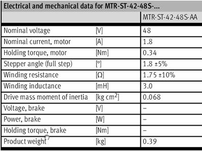
MTR Operating Instructions (part no. 657339)
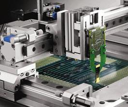
Exercise 1 |
Assembly of stepper motor system
Outcome |
You are able to correctly and safely assemble a stepper motor system.
Reason |
The correct and safe assembly of a stepper motor system will familiarise you with the various components of a system, the purpose of these components and how they are connected together to form a functioning system.
Detailed instructions |
Instructions for the mechanical and electrical assembly of the stepper system:
Safety precaution/system isolation.
Ensure that the main power supply is switched OFF.
Mechanical assembly.
Fix the axis to the support brackets.
Attach stepper motor to the axis via the special adapter flange on the coupling housing and tighten the knurled screws.
Fit the control assembly (SPC200 and Stepper drive unit mounted on H-rail) on the small profile plate using the bracket.
Electrical assembly.
Make the connections for the two limit switches (and the reference switch) - see marking for correct connection.
Check the connection of the signal cable between the SPC200 (stepper motor card) and SEC-ST (connections on left).
Connect the motor cable to the stepper motor and to the to the SEC-ST.
Connect the power supply to the SPC200 and the SEC-ST.
Refer to assembly drawings if necessary.

Stepper motor equipment set complete with linear drive - assembled.
Exercise 2 |
Commissioning of stepper system and 18218v215s introduction to WinPISA.
Outcome |
You are able to correctly and safely commission a stepper system using the main commissioning functions of WinPISA.
Reason |
The correct and safe commissioning of a stepper system will familiarise you with the software and associated settings that must be made before using the system.
Detailed instructions |
This exercise is the basis for all practical exercises with the stepper system. You will get a brief overview of the main functions of WinPISA for stepper systems. Parts of this exercise require a RS232 connection to a SPC200 with a powered ON system! For more information please ask your instructor.
Safety precaution/system isolation.
Ensure that the main power supply is switched OFF.
Electrical assembly secure.
Check all electrical connections are secure.
Check and set DIP switches
Check they are set on the SEC-ST as shown in the image below.
|
|
|
Settings the DIP switches for step mode
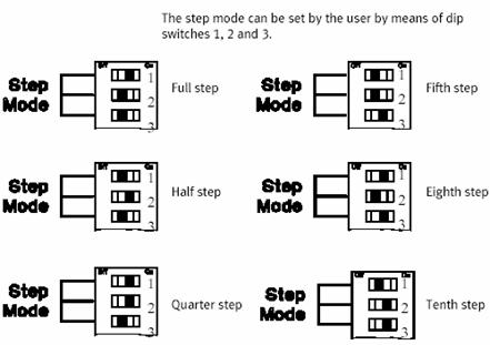
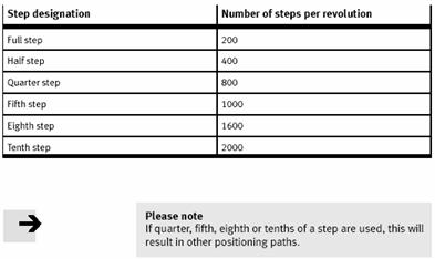
Work on half-step mode or higher (First 3 DIP switches)
Use half-step mode because the frequency resonance is lower and it makes the movement more smooth
Safety check.
|
|
Warning - the next step may cause movement of the slide.
Ensure that everyone in the vicinity is aware the system is being switched on.
Ensure that the path of the slide is clear of obstructions and the slide is sitting in mid position.
Switch on the power supply and check the following.
SPC200 Status LED lights up
Stepper card SEC-ST Power LED lights up
Copying the Project files
The project files used for the exercises are provided by the instructor (they are found on the CD-ROM).
Insert the CD-ROM, open Windows Explorer and locate the following file "festoxx.prj" and folder "festoxx"
The file and folder are in the "resources" folder (cddrive:/drives/resources).
Copy the file and the folder to your hard disk to a location you remember.
Right-click on the file and the folder on your hard disk and click "Properties"
![]()
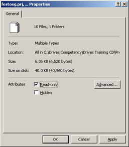
Remove the "Read-only " attribute.
This will enable you to write and modify the project.
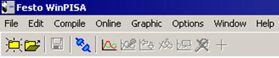
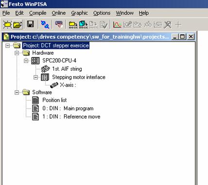
Start WinPISA and open Project.
Install WinPISA on your PC if it is not yet installed.
Start WinPISA.
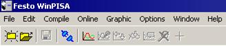
File > Open project.
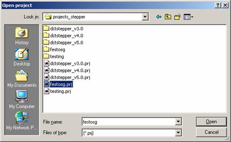
Select appropriate project and click on Open.
Download the project to SPC200.
Click on the "Connect" icon in the program toolbar (you must always connect before your PC can communicate with the SPC200). The plug joins to show that the connection is made.
![]()
![]()
Select your project.
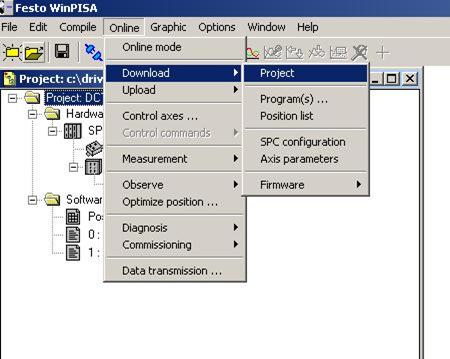
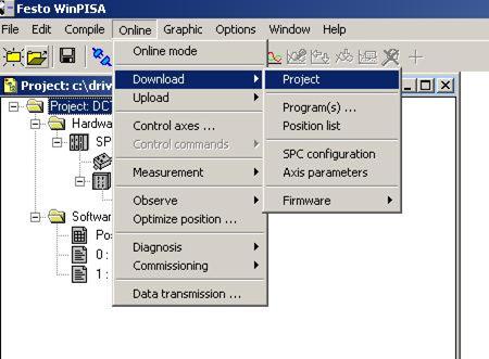
Download project (Online > Download > Project).
Save project.
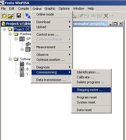
Commissioning stepper motor.
WinPISA provides assistance for commissioning a stepper motor system.
Select Online > Commissioning > Stepping motor
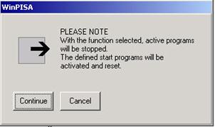
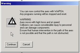
A warning dialog box is displayed.
Click on Continue.
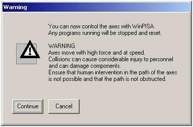
The next window allows you to:
Check status inputs
Activate reference move or emergency travel
Activate movements with negative or positive button
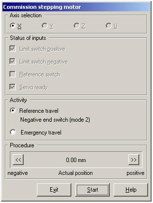
press Start to see the reference travel.
Exercise 3 |
Current reduction in a stepper motor system.
Outcome |
You are able to set current reduction and can explain the advantages and disadvantages of current reduction.
Reason |
Current reduction has advantages and disadvantages that you should understand and be able to explain.
Detailed instructions |
Safety precaution/system isolation.
Ensure that the main power supply is switched OFF.
Check - slide should always be in the mid position of the axis.
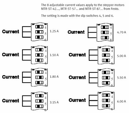
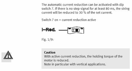
Setting current reduction
Check that the Current Reduction (I-Red.) DIP switch is set to ON.
|
|
|
Setting of DIP switches for current rating of the motor.
Important Important
![]()
Important
![]()
Switch the power supply ON and check the following
SPC200 Status LED lights up.
Stepper card SEC-ST Power LED lights up.
You can ignore error messages on SPC200 (downloading the right project error messages will cancel). If the problem persists, tell your instructor.
Exercise
Carry out the following steps and record your observations.
Q. Move the slide backwards and forwards by hand. How much resistance is there?
|
|
|
|
|
|
Turning current reduction on
Ensure that the main power supply is switched OFF.
Set the Current Reduction DIP switch to OFF.
Reset the system by switching the power supply ON again. Now the motor is drawing full set current.
|
|
|
switch |
off |
on |
|
Step Mode |
--> |
|
X |
|
|
Step Mode |
--> |
|
|
X |
|
Step Mode |
--> |
|
X |
|
|
Current |
--> |
|
X |
|
|
Current |
--> |
|
X |
|
|
Current |
--> |
|
X |
|
|
I-Red. |
--> |
|
X |
|
|
Enable |
--> |
|
|
X |
Q. Move the slide backwards and forwards by hand. How much resistance is there?
|
|
|
|
|
|
Remember: Changes on the DIP switches become valid only after power OFF/power ON sequence.
Saving of energy and reducing the heating of the motor
Can be used as a safety function in applications (reduction of the holding torque in holding position)
Remember: Reduction of the holding torque while holding a position can be a problem for vertical axes.
You can ignore error messages on SPC200 (downloading the right project error messages will cancel). If the problem persists, tell your instructor.
Different current settings.
Test the system with different current setting and see the different torque achieved.
Also change test current reduction with the different current settings.
For safety reasons, do not set the current rating higher than your recommended motor current setting
Once you have completed, make sure that the current reduction setting is in the "On" position.
Q. Is there a difference in torque when we change the current setting?
|
|
|
|
|
|
Analysis of results |
What is the environmental relevance of current reduction?
|
|
|
|
|
|
When should you not use current reduction?
|
|
|
|
|
|
When, precisely, is current reduction (and all DIP switch settings) activated?
|
|
|
|
|
|
When current reduction is activated, what is the percentage of reduction?
|
|
|
|
|
|
What conclusion can you draw from Question 3 regarding safety?
|
|
|
|
|
|
Exercise 4 |
Starting the reference move via WinPISA and the program sequence in a Project.
Outcome |
You are able to conduct a reference move on a stepper system.
Reason |
To work accurately, stepper systems need a reference point from which all positions are calculated. This position is reset in the reference move.
The reference move is essential for the system to know the reference point for all the required positions. It must be conducted:
After powering up a stepper system.
Whenever slippage (loss of steps) has occurred.
Detailed instructions |
Remember:
For basics about WinPISA see Exercise 2.
The power OFF/power ON sequence for capturing DIP switch settings.
Slide should always be in the mid position of the axis when starting an exercise.
Communication between WinPISA and SPC200.
Start WinPISA on your computer.
Select File Open Project.
Select the project file "Festosg.prj" (or the name given to you by your instructor).
Click Open - the project is now open in a dialog box.
Download project (to SPC200).
Click on the "Connect" icon in the program toolbar (you must always connect before your PC can communicate with the SPC200.) The plug joins to show that the connection is made.
![]()
![]()
Download project (Online > Download > Project).
An alert dialog box is displayed.
Click on Continue.
The progress of the download is indicated - this takes approximately 20s.
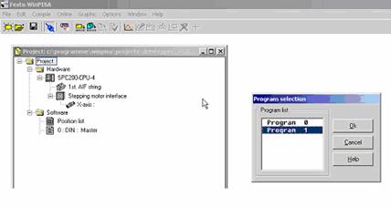
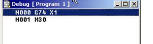
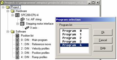
Select Online > Control axes. After a short time a dialog box Program selection appears.
Select Program 1 for the reference move and click OK.
An alert dialog box is displayed.
Click on Continue.
After a short loading time, a dialog box with Program 1 is opened.
Safety check
|
|
Warning - the next step may cause movement of the slide.
Ensure that everyone in the vicinity is aware the system is to be switched on.
Ensure that the path of the slide is clear of obstructions and the slide is sitting in mid position.
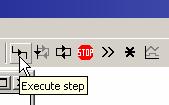
Click on the Execute step icon. The reference move will now be executed. The motor turns until the slide reaches the reference switch. The motor is now set to the reference point.
Note: The reference move is essential for the drive to know the reference point for all following positions. It must be conducted:
After powering up a stepper system.
Whenever slippage (loss of steps) has occurred.
You have now completed the reference move. Close the WinPISA program by clicking the close window icon X at the top right of the program window.
Analysis of results |
When is a reference move necessary?
|
|
|
|
|
|
Exercise 5 |
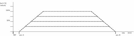
Selecting Speeds (Velocity Profiles).
Two Positions with Different Velocity Profiles
Outcome |
You know how speeds are stored in the system and how they are called.
Reason |
The speeds and positions have to be defined before they can be called in a program. Therefore it is important that you know how these speeds are defined and stored in the system.
Detailed instructions |
Remember:
For basics about WinPISA see Exercise 2.
The power OFF/power ON sequence for capturing DIP switch settings.
Slide should always be in the mid position of the axis when starting an exercise.
If you have undefined starting conditions (movements of the slide) you have to activate a reference move - see Exercise 4.
In this exercise you will:
Create a simple WinPISA program
Experiment with different velocity profiles and positions.
Create a WinPISA program.
For further information on WinPISA, refer to the handout on "First Steps" with WinPISA.
Select File > Open Project.
Select the project file "Festoxx.prj" (or the file given to you by your instructor).
Click Open - the project is now open in a dialog box.
The "Reference Move" program should be there as "Program 1"
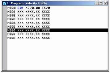
Create a new program to include "Velocity Profiles".
The "Velocity Profiles" program should have the following steps:
|
Step |
Move to Position |
Speed |
|
|
|
|
|
|
|
|
|
|
|
|
|
|
|
|
|
|
|
|
|
|
|
|
|
|
|
|
|
|
|
|
|
|
End Program |
|
Information on Programming with WinPISA
Create the Program
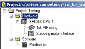
Select the software icon in the project window by clicking on it.
![]()
Select "Insert object" from the "Edit" menu or press the "Insert" key.
Another method would be to right-click on the icon, choose "Insert object" and then left-click.
A "New program" dialogue window will appear.
Enter a program title in the "Title" field, a short description in the "Description" field and the program number required in the "Program no." field of the "New program" dialogue window.
Type in the relevant data.
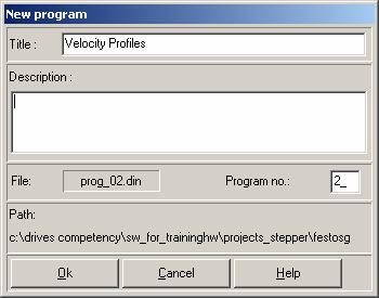
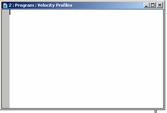
Click Ok to confirm your entries. The new program appears in the project window. The program window is opened.
Programming Codes
The programs for the SPC200 comply with the syntax specified in DIN66025.
An NC record consists of the record number as well as an NC command with the appropriate parameters.
Example:
|
Code |
Description |
|
N0010 |
Record number |
|
G01 |
NC command |
|
G90 |
Type of positioning (optional) |
|
X100.00 |
Position |
|
FX10 |
Parameter |
|
Y100.00 |
Positions |
|
FY80 |
Parameter |
a. Record numbers
Each NC record is indicated by a record number. Record numbers begin with the letter N (for NC record number).
In the SPC200 the record numbers are numbered strictly ascending, beginning with N000 and an incriminations of 1 (thus N000, N001, N002...).
b. Identifiers
|
Identifier |
Description |
|
N |
Identifier for record number |
|
G |
Preparatory function |
|
M |
Auxiliary function |
|
E |
Jump function |
|
L |
Subprogram call |
|
X, Y, Z, U |
Axis identifiers: X-axis, Y-axis, etc |
|
F |
Movement speed |
c. Command Reference
|
Command |
Function |
|
G00 |
Move to position at the highest possible speed |
|
G01 |
Move to position at specified speed |
|
G02 |
Move to position at start/stop frequency |
|
G04 |
Dwell Time |
|
G08 |
Acceleration for approach ramp |
|
G09 |
Acceleration for brake ramp |
|
G74 |
Start reference travel |
|
G90 |
Absolute measurement |
|
G91 |
Relative measurement |
|
M00 |
Program stop |
|
M02 |
End of Subroutine |
|
M30 |
End program with repeat |
Programming
Type in your program in the program window.
Example:
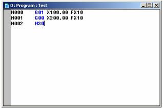
The description of the above program is as follows:
|
NC Record |
Description |
|
N000 G01 X100 FX10 |
Move at 10% of the defined maximum speed to position X=100mm |
|
N001 G01 X200 FX100 |
Move at 10% of the defined maximum speed to position X=200mm |
|
N002 M30 |
Program end with repeat |
The records "N000" and "N002" contain the positioning commands for the axis. In the example positions have been chosen for an axis with the length 300 mm. Adapt the positions according to the possible positioning range.
Move at reduced speed in the program example (e.g. "FX50" corresponds to 50 % of the maximum defined speed). Insert a brief pause after each positioning move (e.g. G04 100) so that you can observe the movement better.
When commissioning multi-axis systems, we recommend that you check all the axes one after the other with your own program.
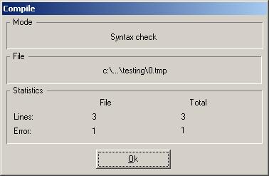
Syntax Check
After completing the program, you need to check the program entered for correct syntax.
To check the syntax of programs:
Make sure that the program window of the program to be checked is active.
Select "Syntax check" from the "Compile" menu or click on the "Syntax check" icon.
![]()
The progress of the syntax check will be displayed in the "Compile" window. Wait until the checking procedure is complete.
Click OK in the "Compile" window to confirm the completed check.
Check the message window. Rectify any errors displayed and repeat the syntax check.
If there is an error, a new window will appear showing you where the error occurs.
Clicking on the error line will bring you to the place where the error occurs in the program box.
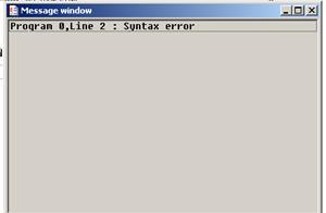
Rectify any errors displayed and repeat the syntax check.
Here in this example, the error is the use of "G00" in line 2. The command reference for "G00" is to travel at maximum allowable speed. When we add "FX10", it contradicts the command.
You can refer to "WinPISA First Steps" notes for more information.
Save the program as "Program 2".
Download project (to SPC200).
Click on the "Connect" icon in the program toolbar (you must always connect before your PC can communicate with the SPC200.) The plug joins to show that the connection is made.
![]()
![]()
Download project (Online Download Project).
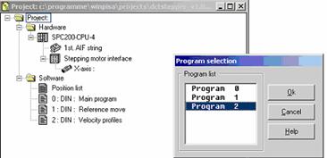
Running the Velocity Profile program
Select program.
Select Online Control axes.
Select Program 2 (Velocity profiles).
Click on Ok.
Controlling the axis from WinPISA
When the program is active you can execute it in two ways by selecting the appropriate icon (Execute step or Start icon).
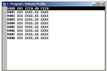
Click Execute step icon.
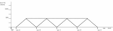
Go through the 8 lines of the program step by step, observing the different velocities (20, 50, 70 and 100% of v max).
Fill in your observations in the "Observation" column.
|
|
Step |
Observation |
|
o |
|
|
|
o |
|
|
|
o |
|
|
|
o |
|
|
|
o |
|
|
|
o |
|
|
|
o |
|
|
|
o |
|
|
Analysis of results |
What is the relationship of SPC200 to SEC-ST and what type of signals does it give? Why do we need a pulse direction generator?
|
|
|
|
|
|
Is the SPC200 always essential?
|
|
|
|
|
|
What dictates the v max of the stepper system?
|
|
|
|
|
|
How do you change the speed for a certain position?
|
|
|
|
|
|
How flexible (precise) are the speeds that can be set on stepper motors?
|
|
|
|
|
|
What must be done if slippage is suspected?
|
|
|
|
|
|
Exercise 6 |
Setting system positions.
Outcome |
You know how positions are stored in the system and how they are called.
Reason |
The speeds and positions have to be defined before they can be called in a program. Therefore it is important that you know how these positions are defined and stored in the system.
Detailed instructions |
For basics about WinPISA see "WinPISA First Steps" notes and Exercise 2.
The power OFF/power ON sequence for capturing DIP switch settings.
Slide should always be in the mid position of the axis when starting an exercise.
If you have undefined starting conditions (movements of the slide) you have to activate a reference move - see Exercise 4.
In this exercise you will experiment with selecting different positions.
Create a WinPISA program.
For further information on WinPISa, refer to the handout on "First Steps" with WinPISA.
Select File Open Project.
Select the project file "Festoxx.prj" (or the name given to you by your instructor).
Click Open - the project is now open in a dialog box.
There should be three programs in the list.
Create a new program to include "Position Profiles".
The "Position Profiles" program should have the following steps; and the movement of the slide should be half the maximum speed:
|
Step |
Move to Position |
|
|
|
|
|
|
|
|
|
|
|
|
|
|
|
|
|
|
|
|
|
|
|
|
Once completed, do a syntax check and save the program as "Program 3"
Download project (to SPC200).
Click on the "Connect" icon in the program toolbar (you must always connect before your PC can communicate with the SPC200.) The plug joins to show that the connection is made.
![]()
![]()
Download project (Online > Download > Project).
Running the Position Profile program
Select program.
Select Online > Control axes.
Select Program 3 (Position profiles).
Click on Ok.
Controlling the axis from WinPISA.
When the program is active you can execute it in two ways by selecting the appropriate icon (Execute step or Start icon).
Click Execute step icon
Go through the 8 lines of the program step by step, observing the different positions (20, 50, 100, 150, 220, 20, 220, 100mm at 50% of v max).
Fill in your observations in the "Observation" column.
|
|
Step |
Position |
Observation |
|
o |
|
|
|
|
o |
|
|
|
|
o |
|
|
|
|
o |
|
|
|
|
o |
|
|
|
|
o |
|
|
|
|
o |
|
|
|
|
o |
|
|
|
Analysis of results |
What factors influence the resolution of a position the slide is to move to?
|
|
|
|
|
|
What influences the distance the slide moves per revolution of the motor?
|
|
|
|
|
|
How can you calculate this?
|
|
|
|
|
|
In the exercises you are activate the program sequences via WinPISA. How do you start programs or projects in practice?
|
|
|
|
|
|
Exercise 7 |
Setting ramps (with different profiles).
Outcome |
You know how to set the ramp up and ramp down for a move to a position.
Reason |
Ramping the speed up and down is an important feature for providing smooth but fast motion. You must know the benefits of ramps and how to set them.
Detailed instructions |
Remember:
For basics about WinPISA see "WinPISA First Steps" notes and Exercise 2.
The power OFF/power ON sequence for capturing DIP switch settings.
Slide should always be in the mid position of the axis when starting an exercise.
If you have undefined starting conditions (movements of the slide) you have to activate a reference move - see Exercise 4.
In this exercise you will experiment with selecting different positions.
Create a WinPISA program.
For further information on WinPISa, refer to the handout on "First Steps" with WinPISA.
Select File > Open Project.
Select the project file "Festoxx.prj" (or the name given to you by your instructor).
Click Open - the project is now open in a dialog box.
There should be four programs in the list.
Create a new program to include "Ramp Profiles".
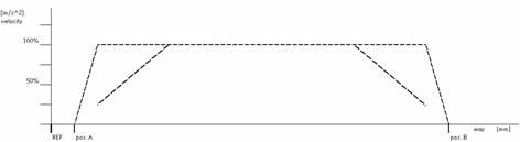
The "Ramp Profiles" program should have the following steps:
|
Step |
Move to Position |
Acceleration |
Deceleration |
|
|
|
|
|
|
|
|
|
|
|
|
|
|
|
|
|
|
|
|
|
|
|
|
|
|
|
|
|
|
|
|
|
|
|
|
|
|
|
|
|
|
|
|
|
|
|
|
|
|
|
|
|
|
|
|
|
|
|
|
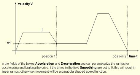
Once completed, do a syntax check and save the program as "Program 4"
An example is given.
|
Example: |
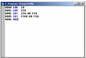
The description of the above program is as follows:
|
NC Record |
Description |
|
N000 G08 X0 |
Accelerate 100% |
|
N001 G09 X20 |
Decelerate 20% |
|
N002 G01 X20 FX0 |
Move at 100% of the defined maximum speed to position X=20mm |
|
N003 G01 X180 FX0 |
Move at 100% of the defined maximum speed to position X=180mm |
|
N004 M02 |
End of Subroutine |
At steps N000 and N001 we set the acceleration and deceleration speed for the movements to follow (N002 and N003).
These acceleration and deceleration speed would be retained until it is changed further down the program.
Download project (to SPC200).
Click on the "Connect" icon in the program toolbar (you must always connect before your PC can communicate with the SPC200.) The plug joins to show that the connection is made.
![]()
![]()
Download project (Online > Download > Project).
Running the Ramp Profile program
Select program.
Select Online > Control axes.
Select Program 4 (Ramp profiles).
Click on Ok.
Controlling the axis from WinPISA.
When the program is active you can execute it in two ways by selecting the appropriate icon (Execute step or Start icon).
Click Execute step icon
![]()
OR
Start continuous run. You can stop at any time by clicking the Stop button.
![]()
![]()
Go through the 8 lines of the program step by step, observing the different ramps.
Fill in the "Ramp" and your "Observation"
|
|
Step |
Ramp |
Observation |
|
o |
|
|
|
|
o |
|
|
|
|
o |
|
|
|
|
o |
|
|
|
|
o |
|
|
|
|
o |
|
|
|
|
o |
|
|
|
|
o |
|
|
|
Analysis of results |
Why are ramps necessary?
|
|
|
|
|
|
How long can a ramp be made?
|
|
|
|
|
|
How short can a ramp be made?
|
|
|
|
|
|
What must be done if slippage occurs?
|
|
|
|
|
|
Fundamentals of servo motors |
Objectives & outcomes |
At the completion of these exercises, you can:
Assemble a servo motor system
Commission a servo system
Conduct a reference move
Use speed control
Use position control
Set ramps
Use torque control
Use electronic gears/synchronous speed control
Describe the benefits and applications of each feature
Reason |
The features and benefits of servo motor control need to be understood (and experienced if possible) in order to be able to design, install, commission, maintain and troubleshoot applications in industry.
Reference Notes |
The following manuals and handbooks are provided on the CD:
Fitting and installation manual (SEC-AC-HW-GB 192346)
Commissioning manual (SEC-AC-SW-GB 192347)
Exercise 1 |
Assembly of servo motor system.
Outcome |
You are able to correctly and safely assemble a servo motor system.
Reason |
The correct and safe assembly of a servo motor system will familiarise you with the various components of a system, the purpose of these components and how they are connected together to form a functioning system.
Detailed Instructions |
Hardware - position and connect hardware.
Mount the DGE on the profile plate.
Mount the servo controller assembly (with FI switch) on the profile plate.
Fit the motor cables and the resolver cable to the motor and connect to the SEC-AC.
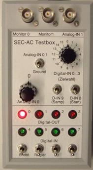
Testbox cable
Take the special cable for the Testbox and
Connect the 2 limit switches cables to the limit switches.
Connect the Testbox cable to the socket in the strip cable.
Use the strip cable to connect X1 and the terminal adaptor (green).
Plug the X1 plug into the X1 socket on the SEC-AC.
Safety precaution/system isolation.
Ensure that the main power supply switch on the servo controller assembly is in the OFF position.
24V power supply is switched OFF.
Connect
230V (servo controller assembly) to mains power.
SEC-AC low voltage power cable to the 24V power supply.
Modem cable to X5 on the SEC-AC and to your PC.
This completes the assembly
Servo motor equipment set complete with linear drive - assembled.
Exercise 2 |
Commissioning of servo system and introduction to Wmemoc.
Outcome |
You are able to correctly and safely commission a servo system using the main commissioning functions of Wmemoc.
Reason |
The correct and safe commissioning of a stepper system will familiarise you with the software and associated settings that must be made before using the system.
Overview |
In this exercise you will:
Establish communication between the PC and the SEC-AC
Set Wmemoc options and load the Festo parameter set
Conduct a manual check of hardware
Check Command and Reference Position dialog box settings
Enable the system
Detailed instructions |
Before powering up check the following.
Testbox and PC connected to controller (do not start Wmemoc yet).
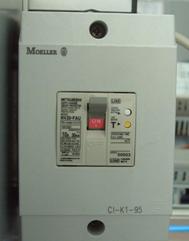
Mains power supply switch is in the OFF position.
This is ON! Must be OFF!
![]()
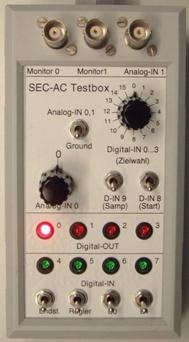
Testbox check
Controller (Regler) enable is OFF (switch down) - the green LED is off.
Power stage (Endst.) is OFF (switch down) - the green LED is off.
All other switches OFF (switch down) and potentiometer switches at 0.
Powering up.
Slide should always be in the mid position of the axis.
Important to power up in the following sequence:
Switch ON the mains power supply switch (230 VAC).
Switch ON the 24V power supply.
After an internal self test, the READY LED on the front of the SEC-AC lights up.
Wmemoc and power off in reverse sequence.
If the following errors occur, rectify them.
|
Error |
Procedure |
|
Error 2 |
Check the power supply to SEC-AC. Ensure proper start-up sequence. |
|
Error 3 |
Check motor connections; cable to servo motor. If needed remove and reconnect |
Establishing communication between PC & SEC-AC.
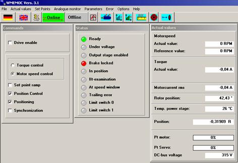
Start Wmemoc on PC (if you start before this an error message will occur). If the communication is OK, Wmemoc appears with 3 windows open - Commands, Status and Actual Values.
Remember:
After starting Wmemoc you have a very useful Help button for any kind of information and troubleshooting.
Setting Wmemoc options.
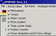
Click on Actual Values from the drop-down menu. Select all values using the tick boxes - this activates the values in the Actual Values dialog box.
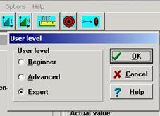
Select Options > User Mode > Expert. This ensures that you have access to all functions of Wmemoc.
Loading the parameter set:
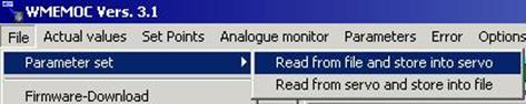
If your instructor asks you to download the parameter set from your PC to the controller, carry out the steps in point 5. The parameter set contains "save settings" for the following exercises including the positions, with velocities and ramps, and other overall settings.
Select File > Parameter set > Read from file and store into servo.
Use the browser dialog box to find the correct parameter set. You should be in the Wmemoc folder called wpa (.wpa is the file extension for parameter sets).
Select (double click) the parameter set for the motor and DGE you are using, ensuring the correct position is selected (vertical or horizontal).
Note: Downloaded parameters are stored in the EEPROM automatically - any changes have to be saved to EEPROM.
Tick the box for the correct axis.
Click OK to load the parameter set. A bar appears showing the progress of the download, which takes approx. 50s. On completion, the message "Data transferred" appears.
Note:
You are provided with complete predefined parameter sets for all Festo axes - servo motor combinations (horizontal and vertical use). These predefined parameter sets give you an initial controller configuration for commissioning. Then the controller loops have to be optimised to the application.
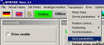
Saving parameter set:
You have two possibilities to save a parameter set:
Select File > Parameter set > Read from servo and store into file
With this action you store data from SEC-AC (EEPROM) into file (on PC).
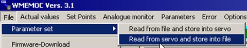
OR
Select Parameters > Save parameters
With this action you store data from SEC-AC (RAM) into SEC-AC (EEPROM). Only now are your data changes saved in case of 24 VDC power failure!
Manual check of hardware.
Check Position value by moving over the slide in any direction to the limit switch.
Check if the counter for the Position value in the Actual Values dialog box is counting up or down.
![]()
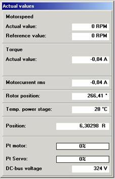
Function of limit switches
If the counter is counting up, when you reach the limit switch, limit switch 1 must light up in the Status dialog box. See image below.
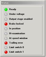
Check in the other direction - the counter must count down and limit switch 0 must light up in the Status dialog box.
Troubleshooting
|
Problem |
Fix |
|
Limit switch does not light up when the end position is reached. |
Check connections. Check function of limit switch. Check limit switch logic. Check the switches (E0, E1-down) on your Testbox. |
|
Counter direction does not agree with limit switch numbering (count up to LM1, count down to LM0) |
Physically change over the limit switches. |
Enabling the system on the Testbox
Switch the Power Stage (Endst.) switch to the ON position (LED lights up).
Switch the controller (Regler) switch to the ON position (LED lights up).
The 7-segment display on the SEC-AC lights up showing "P" (= Positioning mode)
Note that the slide is now locked into position and cannot be moved. You can now hear a high frequency noise from the controller.
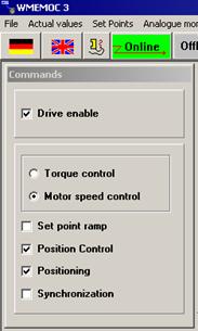
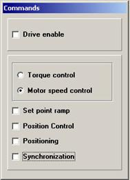
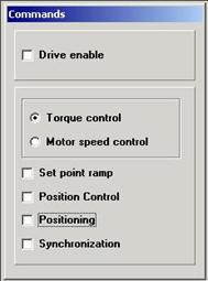
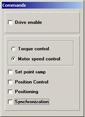
Checking settings for Positioning Mode in the Commands dialog box.
Open the Commands dialog box and ensure the following settings are selected (ticked):
Drive enable
Motor speed control
Position control
Positioning
|
|
Warning - the system will start automatically when enabled/powered.
After every exercise, disable and power OFF the system.
Testbox check:
Controller (Regler) enable is OFF (switch down) - the green LED is off.
Power stage (Endst.) is OFF (switch down) - the green LED is off.
All other switches OFF (switch down) and potentiometer switches at 0.
Close Wmemoc
Switch OFF the 24V power supply.
Switch OFF the mains switch (230 VAC).
Exercise 3 |
Speed control in a servo motor system.
Outcome |
You are able to set the speed in a system and can explain the benefits of speed control.
Reason |
For safety reasons controllers include the speed control feature. You need to know how to adjust it. When commissioning, it is good practice to test the motor in the directions of rotation with the functions of the speed control.
Detailed instructions |
Remember:
For basics about Wmemoc see Exercise 2 and Help function of Wmemoc.
Slide should always be in the mid position of the axis.
For this exercise the servo motor is NOT mounted at the axes!
Important to power up in the following sequence:
mains power
24 VDC
Wmemoc
and power off in reverse sequence.
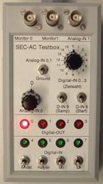
Presetting the Testbox and Axis.
Set all switches on the Testbox to OFF (switches down).
Set the Analog-IN 0,1 switch to Ground.
Set the Analog-IN 0 potentiometer to 0.
Changing settings in Wmemoc.
Go to the Commands dialog box, and select Motor speed control. No other boxes to be checked.
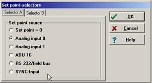
Select Set Point > Set point selection > Selector A and click on "Analog input 0".
Click OK.
This ensures that the controller is checking Analog input 0.

Limiting the speed of the axis.
Note: This is done for safety reasons here, but it is a feature that allows the maximum speed of a drive to be set in applications.
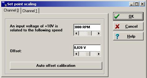
When the motor is connected to axis set the scaling to max. 200 rpm!
Select Parameters > Device parameters > Set point scaling.
Select channel 0 tab and set the scaling to 200 rpm.
This means that at 10V the system operates at 200 rpm. These values are activated immediately.
Click the Auto offset calibration button.
If you have drift on ground - the motor turns without any input signal - this compensates for it. This is the default value and must be adapted during commissioning to suit an application!
Click OK to close the dialog box.

Enabling the system.
On the Testbox:
Check the analog potentiometer is at 0.
Switch Power Stage (Endst.) and Controller (Regler) to enable.
Switch analog switch from Ground to On.
Experimenting with the speed setting
Operate the potentiometer to control the speed and direction of the slide as follows, observing the reaction of the slide. Log your observations in the table below.
|
Experiment |
Observation |
|
Turn potentiometer slowly clockwise |
|
|
Return potentiometer to zero |
|
|
Turn potentiometer slowly anticlockwise |
|
|
Return potentiometer to zero |
|
|
Turn potentiometer full clockwise and switch analog switch from On to Ground |
|
Disable the system for the next exercise.
Optional exercises with free running motor |
It is easer to observe the motor speed if the motor is not limited by the axis.
Setting up the free running motor experiment.
Switch off the mains power supply.
Switch off the Power Stage and controller on the Testbox.
Remove the MTR-AC from axis by loosening the knurled screws.
Place the motor on the profile panel, ensuring that the drive shaft is free of obstructions. Keep people away from it during this experiment.
Setting the motor speed scaling.
Go to Set points > Set point scaling.
Enter the value 3000 rpm.
Switch on the Power Stage and Controller.
Switch on the mains power supply.
Turn the potentiometer to 0.
Switch to Analog IN 0.1 (this activates the potentiometer).
You can now experiment with the motor speed. Carry out these steps and log the results in the table.
Experiment at setting 3000 rpm
|
Setting |
Observation |
|
Slowly turn the potentiometer fully clockwise |
|
|
Slowly return to 0 |
|
|
Slowly turn the potentiometer fully anticlockwise |
|
|
Slowly return to 0 |
|
|
Set turn to any position you like |
|
|
Turn off Analog switch from Ground to Analog and back. |
|
We will now repeat the exercise with the value 6000 rpm. All steps are repeated here for your convenience:
Switch off the mains power supply
Switch off the Power Stage and Controller on the Testbox.
Setting the motor speed scaling.
Go to Set points > Set point scaling
Enter the value 6000 rpm.
Note that the motor will not turn faster than 6800 rpm.
Switch on the Power Stage and Controller.
Switch on the mains power supply.
Turn the potentiometer to 0.
Switch to Analog IN 0.1 (this activates the potentiometer).
Experiment at setting 6000 rpm
|
Setting |
Observation |
|
Slowly turn the potentiometer fully clockwise |
|
|
Slowly return to 0 |
|
|
Slowly turn the potentiometer fully anticlockwise |
|
|
Slowly return to 0 |
|
|
Set turn to any position you like |
|
|
Turn off Analog switch from Ground to Analog and back. |
|
|
That completes
the experiment |
|
Exercise 4 |
Initiating a reference move
Outcome |
You are able to conduct a reference move on a servo system.
Reason |
To work accurately, servo systems need a reference point from which all positions are calculated. This is done after commissioning before normal operation.
Detailed instructions |
Remember:
For basics about Wmemoc see Exercise 2 and Help function of Wmemoc.
Fit the MTR-AC to the axis. (To engage the coupling, push the motor gently home while moving the slide).
Fit and tighten the knurled screws.
Slide should always be in the mid position of the axis.
Important to power up in the following sequence:
mains power
24 VDC
Wmemoc
and power off in reverse sequence.
Safety checks
Testbox check
Controller (Regler) enable is OFF (switch down) - the green LED is off.
Power stage (Endst.) is OFF (switch down) - the green LED is off.
All other switches OFF (switch down) and potentiometer switches at 0.
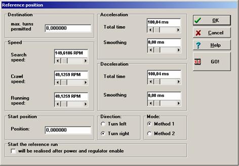
Click on the Reference move icon to open the Reference Position dialog box.
![]()
In the Reference Position dialog box, check that Method 1 is selected as the Mode (bottom right).
|
|
Warning - The next step will cause movement of the slide - make sure there is nothing obstructing the path of drive and that everyone around you knows you are going to start.
Cover the controller enable switch on the SEC-AC with one hand ready to switch off if the system is noisy or movement is erratic.
Switch the Testbox to "On" first.
Switch the Controller (Regler) to ON
In the Reference Move dialog box, start the reference move by clicking on GO!
The slide moves to the reference point and stops.
If the system is noisy or moves erratically, switch off the Controller Enable immediately and tell your instructor.
You have now completed the reference move.
Exercise 5 |
Setting system positions, speeds, and ramps.
Outcome |
You know how to define position sets and three ways of selecting positions.
Reason |
The positions, speeds and ramps have to be defined before they can be called in a program. Therefore it is important that you know how these parameters are defined and stored in the system. It is also important to know
Overview |
In this exercise you will
See a set of defined positions
Select positions using the Go to Destination dialog box
Learn three ways of moving between positions
Detailed instructions |
Remember:
For basics about Wmemoc see Exercise 2 and Help function of Wmemoc.
Slide should always be in the mid position of the axis.
Important to power up in the following sequence:
mains power
24 VDC
Wmemoc
and power off in reverse sequence.
Start a reference move, see Exercise 3.
Checking positions
Note: you do not need to enter the positions - a set has been downloaded as part of the parameter set. In the exercises you use predefined positions with ramps and velocities - making some changes as required.
Click on the Destination icon.
![]()
The Destination 0 dialog box appears.
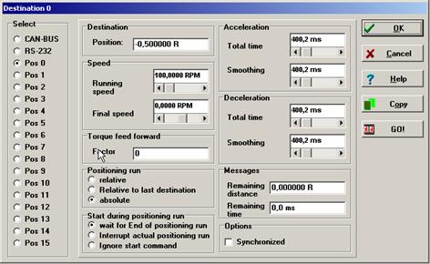
The table below shows you the positions sets defined in the parameter set loaded in the SEC-AC. By clicking on the numbered buttons on the left you can see the data for each position.
Table of position sets.
|
Position number |
Position |
Running Speed (rpm) |
Positioning mode * |
Acceleration (msec) |
Deceleration(msec) |
|
|
|
|
Abs |
|
|
|
|
|
|
Abs |
|
|
|
|
|
|
Abs |
|
|
|
|
|
|
Abs |
|
|
|
|
|
|
Abs |
|
|
|
|
|
|
Abs |
|
|
|
|
|
|
Abs |
|
|
|
|
|
|
Abs |
|
|
|
|
|
|
Abs |
|
|
|
|
|
|
Abs |
|
|
|
|
|
|
Abs |
|
|
|
|
|
|
Rel |
|
|
|
|
|
|
Rel |
|
|
* Note that Positioning mode is called "Positioning run" in Wmemoc.
Moving to selected positions
Switch on the Controller Enable (Regler) switch.
Select the Go To Destination button in tool bar.
![]()
Click on buttons in the dialog box to move to a selected position. (If you are continuing directly from the reference move exercise, the slide should be in the reference position).
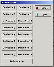
Select the positions in the sequence shown in the table below. Tick them off in the Step column as you go and make notes on the right on what you observe about the motion of the slide.
Upon completion, disable the set for the next exercise.
Logging results |
|
Step |
Move to position |
Observation (viewed from the front) |
|
|
Reference move |
|
|
|
|
|
|
|
|
|
|
|
|
|
|
|
|
|
|
|
|
|
|
|
|
|
|
|
|
|
|
|
|
|
|
|
|
|
|
|
|
|
|
|
|
|
|
|
|
|
|
|
|
|
|
|
|
|
|
|
|
|
|
|
|
|
|
|
|
|
|
|
|
|
|
|
|
|
|
|
|
|
|
|
|
|
|
|
|
|
|
|
|
|
|
|
|
|
|
|
|
|
|
|
|
|
|
|
|
|
|
|
|
|
|
|
|
|
|
|
|
|
Exercise 6 |
Torque control.
Outcome |
You know how to control the torque of a system and know how to use torque control in applications.
Reason |
Torque control is an important feature and benefit that offers safety to man, machine and products. It is important that you are familiar with it and how to make best use of it.
Detailed instructions |
Remember:
For basics about Wmemoc see Exercise 2 and Help function of Wmemoc.
Slide should always be in the mid position of the axis.
Important to power up in the following sequence:
mains power
24 VDC
Wmemoc
and power off in reverse sequence.
Start a reference move, see Exercise 3.
Preset the Testbox and Axis
On the Testbox, check:
Controller (Regler) enable is OFF (switch down) - the green LED is off.
Power stage (Endst.) is OFF (switch down) - the green LED is off.
All other switches OFF (switch down) and potentiometer switches at 0.
Check the slide is in the middle of the axis (move by hand if needed).
Testbox check
Changing the software settings
You are going to control the torque via a dialog box in Wmemoc - so this must be set first.
In the Commands dialog box, select Torque control. All other options should be unchecked/deselected.
Select Set Points > Set point selection > Analog input 0.
Click OK.
Enabling the system.
|
|
Safety warning: the next step may cause movement of the slide.
Select Parameters, Device parameters, Set point scaling
Check selected Torque in Nm (bottom left)
Note that all values are immediately effective!
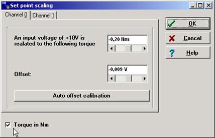
Set the scaling to 0.2Nm.
|
|
Safety warning: Do not set more than this! Danger of injury!
Click on auto offset calibration.
Ensure there is nothing obstructing the path of drive and set the slide in the middle of the axis.
Ensure everyone around you knows you are going to start.
Setting the required desired value.
On the Testbox:
Set the Analog-IN 0 to 0
Switch enable Power Stage and Controller to ON
Switch to Analog IN 0.1 (from Ground)
Follow the instructions under Setting below. By observing the actual values dialog box, establish at what torque the slide starts to move.
|
Setting |
Observation |
|
Slowly turn the potentiometer fully clockwise |
|
|
Slowly return to 0 |
|
|
Slowly turn the potentiometer fully anticlockwise |
|
|
Slowly return to 0 |
|
|
Turn off the Analog switch (Ground) |
|
|
Set the potentiometer to any position |
|
|
Turn on the Analog switch. |
|
|
Q1. When does the slide start to move? (Value in A) |
|
|
Q2. Why does the slide start to move? |
|
|
Q3. Move the slide to an end position - either by hand or using the software. |
|
|
In the end position gradually turn the potentiometer to move the slide to the other end while holding it. Watch the Force value in the Actual value dialog box. When does the axis have a weak spring effect? (When pushed from the end position, the slide returns on its own) |
|
|
Q4. Gradually turn the potentiometer to increase the force. At what setting does the axis have a strong spring effect? (Difficult to move from end position, moves back quickly if released) |
|
|
Q5. In this system, what would you consider a safe setting that would avoid injury to people? |
|
Disable the system for the next exercise.
Exercise 7 |
Use of speed synchronous positioning
Outcome |
You are familiar with the electronic gear of the system and can explain the concept of synchronous movement and the electronic gear and know how to use it with Wmemoc.
Reason |
You are familiar with speed synchronous positioning and the features and benefits it offers.
Detailed instructions |
Remember:
For basics about Wmemoc see Exercise 2 and Help function of Wmemoc.
Slide should always be in the mid position of the axis.
Special conditions for this exercise:
You need two servo axes.
Servo axes 1 is Master
Servo axes 2 is Slave
The servo motors must be disconnected from the axis.
Important to power up in the following sequence:
mains power
24 VDC
Wmemoc
and power off in reverse sequence.
Demonstration of electronic gear using two SEC-ACs in Master -Slave mode.
Connect the encoder cable to the socket X11 OUT (Master) on the SEC-AC to the socket X10 IN (Slave) on the SEC-AC.
Connect programming cable from your PC to Master.
Open Wmemoc.
Make the settings for speed control, see Exercise 3
Open Wmemoc
Load the parameter set "DCT_Servo_V3.0_for_participants.WPA" to the Master.
Check the following settings for the Master.
Connect your programming cable from your PC to Slave.
Open Wmemoc
Load the parameter set "DCT_Servo_V1.0 slave synchron.wpa" to the Slave.
Check the following settings for the slave.
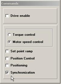
Open the Synchronisation dialog box of the slave.
Select Parameters > Synchronisation.
Set the switches and settings in the Synchronisation dialog box. Ensure they set according to the following table.

Switch Power Stage and Controller on Testbox of the Master to enable ON.
Switch Power Stage and Controller of the Slave to enable ON.
Turn the shaft of the Master servo motor.
Demonstrate different gear factors by clicking on "f2" (see picture synchronization).
![]()
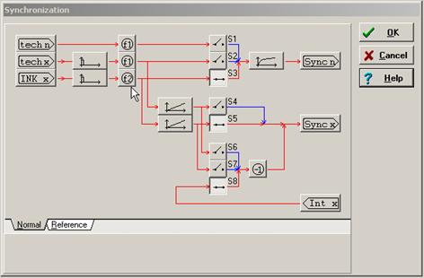
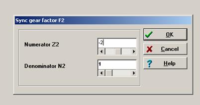
Here you can set different sync gear factors for your Slave
Change the values to see the effect of synchronisation
|


