Thin film interference
The colouring you can notice on the surface of a soap bubble or that
of a puddle is a result of light interference on thin films. In these examples
the thin films are of soap/water solution or oily substances on water. Let us
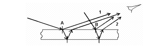
consider a thin film of an arbitrary transparent material of refractive index ![]() , on which white light is incident. The thickness d of
the film is assumed constant. Incident light is partially reflected and
refracted at the air/film interface. The refracted light reaches the lower
surface of the film where it subsequently undergoes reflection and refraction.
Light reaching the observer is a superposition of the coherent light beams
reflected from the upper and lower interfaces (see the figure).
, on which white light is incident. The thickness d of
the film is assumed constant. Incident light is partially reflected and
refracted at the air/film interface. The refracted light reaches the lower
surface of the film where it subsequently undergoes reflection and refraction.
Light reaching the observer is a superposition of the coherent light beams
reflected from the upper and lower interfaces (see the figure).
The superpos 16416g615q ition results in an interference pattern. According to
the difference in optical path length between the light beams reflected from
the top and bottom interfaces, some wave lengths reinforce each other and
interfere constructively. Other wavelengths undergo destructive interference
and cannot be seen. The condition for interference is that the difference in
optical path length be within the coherence length of incident light. That is why
the film needs to be thin. The difference in optical path length between rays 1
and ray 2 is almost ![]() because the plate is so thin. When you compute the difference
in phase you have to recall adding radians which is the
phase shift of rays 1 upon reflection.
because the plate is so thin. When you compute the difference
in phase you have to recall adding radians which is the
phase shift of rays 1 upon reflection.
The observer's eye collects light from different points of the film. As a result, he sees a wide range of colors. Consider that the reflected beams originating in region A interfere destructively for red wave lengths, for instance. Then A looks blue-greenish. On the other hand, the difference in optical path length of the reflected rays originating in region B is shorter so that the blue-green wavelengths interfere destructively and B looks red. In practice all the rainbow colors can be seen.
The irregularities of the bright interference fringes are explained by the fact that:
1) the thickness of the film is not the same at any point;
2) the refractive index is not constant.
Reflection is an unwanted effect in any optical instrument because it produces light losses at the lens surface and image distortion by multiple internal reflections. A solution to this problem is provided by antireflection coatings. An antireflection coating is obtained by vaporizing a dielectric substance (for instance magnesium fluoride or thorium fluoride) and subsequently allowing it to deposit onto an optical substrate (glass, plastic etc.) in vacuum. The composition and the thickness of the film is chosen such that its refractive index be a geometric average of the refractive indices of the two media with which the film is in contact. Then the amplitudes of the two reflected waves that interfere destructively are equal, resulting in a zero minimum.
Let us calculate the minimum thickness of an
antireflection coating of magnesium fluoride (![]() ) on flint glass
(
) on flint glass
(![]() ) which will
annihilate reflection of
) which will
annihilate reflection of ![]() incident light. For simplicity, we will
consider that the incidence of light is normal to the film.
incident light. For simplicity, we will
consider that the incidence of light is normal to the film.
Note that the refractive indices are chosen such that both the reflected waves undergo a phase shift of π radians (recall that this phase shift occurs when the refractive index of the incident medium is less than the refractive index of the medium where light is transmitted). Consequently the difference in phase between them is due to the difference in optical path length, that is
![]()
The condition for a minimum of interference is
![]()
when m is
an integer number (positive or negative). The minimum thickness
corresponds to the minimum difference in phase, i. e. ![]() . Then
. Then
![]()
and numerically
![]() .
.
As you can notice from the above example, antireflection coatings are designed for definite incident wavelengths. Antireflection coatings which destroy reflection in the whole visible range are multiple-layered.
A thin wedge is an optical device made of two thin plates of a transparent dielectric material (glass, for example) that are in contact at one end (the vertex of the edge) and slightly separated at the opposite end (see the figure).
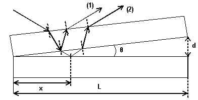
Consider a beam of incident monochromatic light. An observer looking from above the wedge will notice an interference pattern whose fringes are normal to the incidence plane of light. This is the result of superimposing two coherent waves: 1) the wave reflected by the lower surface of the upper plate and 2) the wave reflected by the upper surface of the lower plate.
We designate by d the variable thickness of the wedge. The
distances will be measured in the horizontal Ox direction starting from
the vertex of the wedge, ![]() . Then the thickness
. Then the thickness ![]() is a function of the
coordinate
is a function of the
coordinate ![]() ,
, ![]() , such that
, such that ![]() (the plates are in
contact at the origin) and
(the plates are in
contact at the origin) and ![]() (the plates are farthest
apart at
(the plates are farthest
apart at ![]() ). Since is very small (of a
human hair order of magnitude), we
can write:
). Since is very small (of a
human hair order of magnitude), we
can write:
![]()
The difference in phase between the two coherent beams which interfere is
![]()
In writing the above expression we took into account the phase shift that beam 1 undergoes upon reflection. We also approximated
the difference in path lengths between the two waves by ![]() which is valid for such small inclinations of
the upper plate.
which is valid for such small inclinations of
the upper plate.
Let us find the position of the minima and maxima along the wedge. The condition for a minimum of interference is
![]()
By using this condition in equation , that expresses the difference in phase as a function of the coordinate, we will eventually find the position of the interference minima. Firstly, we have
![]()
which represents the condition for a minimum of interference in the optical wedge
 .
.
In the above
expression ![]() denotes the position
of the minimum of the m-th order along the
denotes the position
of the minimum of the m-th order along the ![]() axis and
axis and ![]() is the corresponding
thickness of the wedge.
is the corresponding
thickness of the wedge.
To find ![]() , we use in . Then
, we use in . Then
![]()
and consequently
![]() .
.
Note that the first minimum occurs at the points where the plates are in contact. We expected this result since the difference in optical path length is null there and the corresponding difference in phase is just π (the phase shift of beam 2).
The condition for a maximum is
![]()
and
![]()
Dividing by 2π and rearranging the terms we find
![]()
Note that ![]() is not possible from a
physical point of view; it would mean that the zero-th order maximum occurs at
a point which does not belong to the wedge. The position of maxima is given by
is not possible from a
physical point of view; it would mean that the zero-th order maximum occurs at
a point which does not belong to the wedge. The position of maxima is given by
![]()
According to equations and , the spacing of two consecutive minima or maxima is the same
![]()
It varies proportionally to the wavelength
and inversely proportional to the angle of the wedge. Observe that an optical
wedge can be used to measure very accurately the diameter of thin wires or
thicknesses of very fine objects. Indeed, knowing ![]() and measuring
and measuring ![]() , one can easily find
, one can easily find ![]() and
subsequently
and
subsequently ![]() .
.
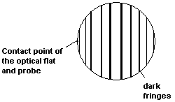
Thin wedges are also used for checking the
flatness of surfaces. To this effect an optical flat is used in conjunction
with the work piece being inspected. An optical flat is a disk of high-grade
quartz glass which is approximately ![]() thick and has one side polished, with a deviation in flatness
less than 50nm. The optical flat and the surface being inspected touch at only
one point thus forming an air wedge. If the surface is perfectly plane, a
pattern of equally spaced dark and bright fringes is obtained when the system
is illuminated with monochromatic light. If the surface being inspected is not
plane, the interference fringes exhibit irregularities which are determined by
the variable thickness of the work piece.
thick and has one side polished, with a deviation in flatness
less than 50nm. The optical flat and the surface being inspected touch at only
one point thus forming an air wedge. If the surface is perfectly plane, a
pattern of equally spaced dark and bright fringes is obtained when the system
is illuminated with monochromatic light. If the surface being inspected is not
plane, the interference fringes exhibit irregularities which are determined by
the variable thickness of the work piece.
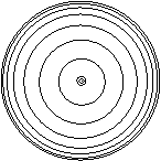
![]()
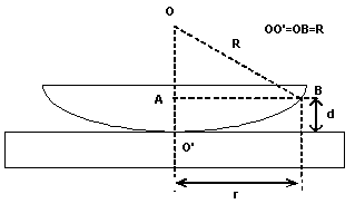
The interference pattern consists in
consecutive dark and bright consecutive circular fringes, each corresponding to
a certain thickness d of the wedge. In the following we will compute ![]() (the difference in
optical path length between the reflected interfering waves) as a function of
the lens radius
(the difference in
optical path length between the reflected interfering waves) as a function of
the lens radius ![]() and the distance
and the distance ![]() from the symmetry axis
to the point where d is computed (
from the symmetry axis
to the point where d is computed (
In ΔOAB, we have

which results in
![]()
Since ![]() , we can neglect the first term in the previous equation.
Thus
, we can neglect the first term in the previous equation.
Thus
![]() .
.
Next we apply the conditions for maxima and minima of interference for the optical wedge
![]()
and
![]()
Then the radii of the bright and dark fringes are given by

and
![]() .
.
If we want the counting to start from ![]() for the bright rings
as well, we can use
for the bright rings
as well, we can use
 .
.
As expected, the central fringe is always a
minimum. Note that the radii increase as ![]() with
with ![]() . Consequently the rings become more
and more closely spaced as the interference order
. Consequently the rings become more
and more closely spaced as the interference order![]() increases (see the figure). So we cannot speak about a
constant spacing.
increases (see the figure). So we cannot speak about a
constant spacing.
However the area
between two consecutive rings of the same kind is constant. Indeed, this area
varies proportionally to![]() , i.e. to
, i.e. to ![]() .
.
|
