Understanding FEMM working
All that which involves radius / diameter can be solved as Polar models
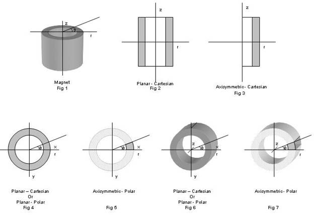
Fig 1 shows the cylindrical magnet
Fig 2 shows the section view. This type of model can be solved for round air core solenoid and also for ring magnet with radial magnetic profile (from inner to outer radii), with axial magnetic profile. In FEMM, the 3D model can also be solved by specifying the depth of the problem
Fig 3 shows the axisymmetric section view. This type of model can be solved for all round air core solenoids and for cylindrical magnet with axial or radial type of magnetization.
Fig 4 shows the Top view of Fig 1. This type of model can be either solved in Polar or Cartesian coordinate systems. All type of Outer circumferential magnetization and Inner circumferential magnetization can be solved for multi-pole magnets. The multi-pole magnetizing fixture can also be solved by this type of solving method. Fig. 6, the depth of the model is specified for solving the problem. While solving, the depth is specified and in an assumption, the problem is solved in 3D mode, however the model can only be in 2D.
Fig 5 shows axisymmetry section of the Top view of Fig 1. This type of model can be solved in Polar coordinate systems. All type of Outer circumferential magnetization and Inner circumferential magnetization can be solved for multi-pole magnets as well as multi-pole magnetizing fixtures.
In Fig 6, the solvation of the problem in Planar mode is shown.
In Fig 7, the solvation of the problem in Axisymmetric mode is shown.
All the model that involves length, breadth and height can be solved by Cartesian (see figure)
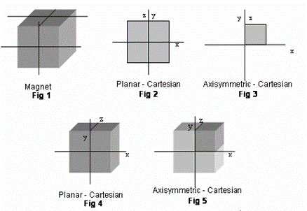
Fig 1 shows a cubical magnet and the way it can be solved is shown in Fig 2 as Planar-Cartesian and Fig 3 as Axisymmetric-Cartesian, while the same can be solved in a 3D-mode, by specifying the depth of the model in the problem as shown in Fig 4 and Fig 5.
In Fig 5, the solvation of the problem in Axisymmetric mode is shown.
Understanding Working FEMM
Step by Step Working Details
The model can be made by making the origin as the reference point either for Planar or Axisymmetric case.
Define the problem as Planar or Axisymmetric using the Problem command in the menu.
Define the coordinate system as Cartesian or Polar using the Grid Set Grid command from the menu.
Define the materials using the Properties Materials Add Property to add new material.
To add new material for Magnetostatics application, Material name, material properties like permeability, coercive field, BH data point in case of Non-linear material, conductivity must be fed in the relevant text box mentioned in the material dialog box.
If the material is available in the library, the material can be selected and added from the library.
To select the material from the library go to Properties Materials Library Add Material
Sketching
Now to sketch the drawing, go to menu, select Operation Node. Use Tab key to enter the dimension so that the nodal points are placed at the respective location.
To draw a segment, go to menu, select Operation Segment and select the respective points. Once two points are selected, a segment is drawn.
Similarly to draw an arc, go to menu, select Operation Arc Segment and two points are to be selected and the arc angle is to be specified with number of segment in the arc.
After sketching, each closed area is termed as "Block" and each block must be represented by material properties, for which the block is to be defined by selecting the commands
To define a block, go to menu, select Operation Block and each area is specified by a block by clicking on the area or by the specific point, pressing the Tab key entering the points where the block to be specified.
Sketchs can also be imported from AutoCAD-DXF file as a 2D model. For importing the DXF file, go to the menu, select File Import and select the respective file from the source folder.
After importing the 2D model of the file, the block is to be defined by using the block icon or using operation command from the menu bar.
Properties
Defining Material
For any type of analysis, the material has to be defined; even the material has to be Air.
To define the material properties, go to menu, select Properties Materials, if new material to be added or defined, click Add Material.
If the material is available in the Library, go to menu, select Proprieties Materials Library and add the material available in it.
If the material is not available in the library, the material can also be defined in the Material Library by selecting the New Entry command in it. After adding the material in the library, the same can be selected for computation.
Defining Boundary
One has to define the boundary for the problem, such that the computation is carried out in a specific region only
To define the boundary, go to menu, select Properties Boundary and click Add Property, the required boundary condition may be specified and following are the available boundary condition
Prescribed A - Magnetic Vector Potential
Small Skin Depth
Mixed
Strategic Dual Image
Periodic
Antiperiodic
Define Circuit Property
The circuit has to be defined for any carrying current conductor. To define the circuit property, go menu, select Properties Circuits and click Add Property. The circuit may be defines as Series or Parallel and the input current or current density may be specified.
The
circuit property may be also defined in the material property itself, while
defining the material, by specifying the current density to the material
itself. The current density may be calculated as the product of number of turns
times the input current to the ratio of the conductor cross section area
(in case that the conductor is defined as whole block).
To define circuit property while defining the material, go to menu, select Properties Materials, if new material to be added or defined, click Add Material and specify the current density in the respective Text Box given.
To define the current density for a material already added, go to menu, select Properties Materials, if new material to be added or defined, click Modify Material and specify the current density in the respective Text Box given.
|
