finalRender 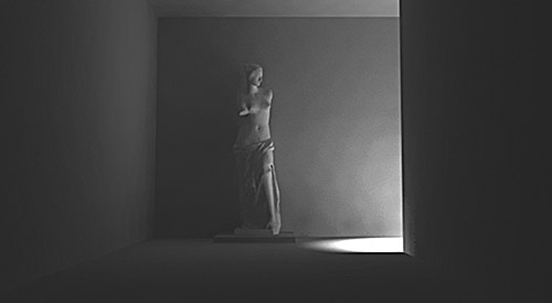
Welcome
Thank you for purchasing finalRender for 3ds max.
finalRender is the ultimate rayttacing and Global Illumination system for 3ds
max, offering unparalleled power to the user. We hope you find that finalRender
allows you to create the incredible effects you are looking for. Our philosophy
is to integrate software design and ease-of-use into our products. If you find
we need to improve in some areas of finalRender please let us know! finalRender
is under constant development and we need your help to improve it. We love to
hear from our customers and we will always answer your emails. It doesn't
matter if it's a new idea, a bug, or you just want to give us your opinion.
Tell us what you think and what you would like to see in upcoming releases.
finalRendor may seem a bit confusing at first, but if you follow the tutorials
and watch the training videos, the ideas of finalRender's design should become
more dear to you. Be aware that finalRender is an extremely powerful tool that
offers many new concepts that you might not have seen before. Stick with this
manual and try to work through it in easy stages, don't make the mistake of
trying to learn everything in one gol
Stay in Contact
You can reach us most easily by email. Our approach is to supply software
through author- ized dealers, so please remember that your dealer should be
your first contact for help or more information. Only registered users will get
MAXimum supportl. Our contact address is as follows:
cebas Computer GmbH email: [email protected]
Recommended System
finalRender is a software plug-in for Windows based platforms
that run 3ds max 4 only. The preferred operating system is Windows 2000.
finalRender will run with any workstation that 3ds max is installed on. We
recommend a minimum of 256MB RAM and a fast processor (1000Mhz at least, or
better yet l.8GHz).
Installation
CLAMP-System
Before you can begin the installation of finalRender our CLAMP-System must be
installed and activated by a rebooting the PC. The CLAMP-System is a software
protection system developed by cebas Computer GmbH for Win9x, Windows NT and
Windows 2000. It is implemented as a system service under Windows NT and
Windows 2000, Win 9x systems will not require the system service CLAMP-SYSTEM.
Note that this system service must be active at all times, but don't worry as
the installation of CLAMP-System is fully automatic and transparent to the
user. On the installation CD-ROM you will find a file called CLAMP- System.EXE,
double click this file to start the installation process. There is no need to
set any parameters for this installer as everything is done automatically. The
PC however must be rebooted before you can proceed with the installation of
finalRender. There only needs to be one instance of the CLAMP-System installed,
regardless of the amount of different cebas plug-ins you may have. If you
accidentally deactivate or forget to install Clamp-System before installing the
plug-in, a warning message will show up when you start the installer.
Plug-In Installation After
rebooting you should decide how and where you would like to install
finalRender. If you haven't changed your original 3ds max installation on your
hard disk it should look like this:
[drive letter]:\3DSMAX
[drive letter]:\3DSMAX\PLUGINS
[drive letter]:\3DSMAX\STDPLUGS
[drive letter]:\3DSMAX\SCENES
If for any reason you have changed the standard installation of 3ds max you
will have to adjust where you placed your install directories. To start the
automatic installation of finalRender you have to start die installation
program called "finalRender.exe". You'll find this file on the
finalRender installation CD-ROM. To run the installer, either double click on
its icon in EXPLORER or choose RUN in the Start menu and type [cdrom]:\
finalRender.exe. After several seconds the installation program will come up
and you will be prompted to type in the relevant directory path for each file
category. If you haven't changed the original installation of 3ds max then the
installer will automati- cally suggest your original 3ds max installation path.
You must supply the root directory of 3ds max as the installer will not accept
any other directory. The installation program offers two installation options.
Full Modeling License Network Install finalRender supports a network rendering
mode. If you do not have a render farm or multi- ple PCs with 3ds max installed
you do not need to worn' about the network option. Users who wish to use their
render farms with finalRender, must remember to install the CLAMP- System onto
each of their slave machines before choosing the Network Install option and
installing finalRender. The network installation option will install the
necessary DLLs only. To get a trouble free network installation you must use
the Network install option. If you try to create a manual network install it
will not work. You may load and edit scene files that contain finalRender effects
on those machines that have a network install. No error messages or missing
plug-in messages should appear when you load a finalRender scene file onto a
correctly installed net work render machine. However, on these machines there
will be no menu options or any other editing available of finalRender
parameters. Of course rendering and editing of other parts of the scene will be
possible.
Note:
Network Rendering will not work if you manually copy the relevant finalRender
DLLs onto each render node! You must install the CLAMP-System onto each of your
slave machines before choosing the Network Install. Now the installation
process is complete you are ready to authorize finalRender.
I skipped the license Part cause do YOU need IT? (Strolchi)
About finalRender
finalRendcr is a modern raytracing system for 3ds max, by using a physically
correct approach to calculate diffuse and non-diffuse lighting situations,
finalRender is able to create images of outstanding quality. The method used to
render photo realistic light distribution is called Global Illumination.
Distributed raytracing and massive parallel rendering techniques enable the
user to use these rendering effects with the least amount of processing time.
finalRender is a complete raytracing system, which is fully integrated into 3ds
max and appears to the user as a core component. In fact a rendering system
like finalRender touches nearly every module within 3ds max. You'll find
enhanced finalRender features using lights, atmos- pheric effects &
materials.
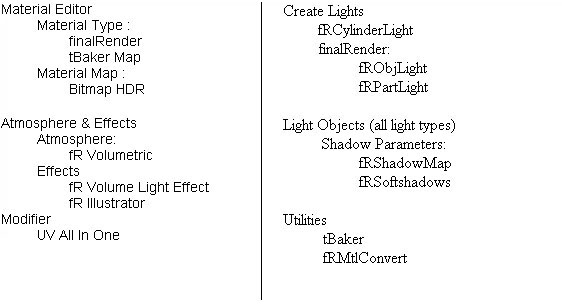
Below you can see a map of new features added to 3ds max by finalRender.
What else is finalRender?
finalRender doesn't just offer one of the fastest raytracing systems on the
market, it also contains one of the most successful illumination plug-ins ever,
LumaObject. LumaObject is now a core part of the finalRender raytracing system
and is closely integrated to give full access to the core functionality of
finalRender.
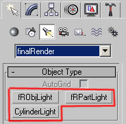
LumaObject offers two new light types, fRObjectLight (formerly LumaObject) and
fRParticleLight (formerly LumaParticle). LumaObject was the first plug-in for
3ds max to offer real area lights. This means that any 3ds max model can be
turned into a light-emitting object. There is nearly no restriction on the type
of object that can be turned into an area light source, polygons, nurbs,
patches and any particle system (meta particles or mesh-based particle systems)
may all be used.
Another advantage offered by LumaObject, is die option to fake Global
Illumination with vastly improved render rimes. A special "light"
bouncing mode makes it possible to turn an object into a real light reflector
and in many cases die results can look like a Radiosity or GI rendering. This
feature helps LumaObject to ease the problem of long render rimes associat- ed
with Global Illumination. To learn more about this feature check out the sample
files in the fRObject light folder. Some of those sample files mimic the
lighting found in the GI- Samples. It's up to you to decide if you wish to use
GI or a fRObject light rendering method.
. . . and a Bunch of Volumes
For a raytracing system like finalRender to work all kinds of visual phenomena
must be han- dled correctly. The lights and materials play a big part in every
raytracing system, but also volume lights & atmospheric effects also play
an important role in the overall realism of your image.
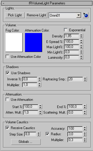
To handle these effects BunchOfVolumes™ (an advanced volumetric cebas
plug-in) has been integrated as a core part of the finalRender raytracing
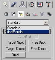
system. Volume light effects can be easily added using the standard 3ds max
commands. One of the unique features of finalRender volume lights is the option
to create them as Render Effects in 3ds max. These Volume light effects can be
rendered in near real-time without having to render a complex scene every time
the volume effect changes. As well as enhancing die rendering speed of
volumetric effects, finalRender also offers advanced controls and settings
compared to stan- dard volume lights. Volume light effects will render correctly
with Global Illumination using an frVolumetricLight assigned to any light
source in the scene. For more information about the interaction between volume
lights and Global Illumination, please read the next chapter.
Description of Rendering methods
In this chapter we will explain how understanding Global Illumination can help
you create better images. This chapter is very important to read because it
contains important explana- tions about die concepts and ideas used in
finalRender, which will help you to understand the techniques that you will use
to improve your renderings. First let us explain the differences between the
illumination methods used in finalRender.
A 3D scene is usually divided into the following basic parts:
1.) Geometry (the 3D models; a building, monster, spaceship)
2.) Textures/Materials (the surface definitions)
3.) Light/Illumination (direct lights)
4.) Animation/Movement
5.) Special F/X (video post)
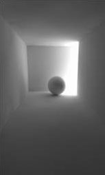
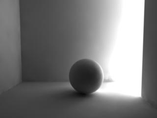
Local Illumination (direct light)
This is the standard implementation of calculating any illu- mination effects
in a 3D scene. Using direct illumination is a straightforward approach to
render an image; only where the light rays strike an object does an
illumination calculation take place. In all other areas, non-illuminated or shadows,
there will be no light calculation at all. The big advantage of this method is
mat, even on slow processors, fast rendering speed is achieved. The drawback
however, is the unrealistic look of the lighting in the image. Looking at the
illustration on the right, we see the light hit the back of a room. As this is
the only area where the light is visible, all other areas will show a pure
black color (the standard ambient color). For many years 3D artists have
learned to live with this and have found many ways to fix unrealistic
renderings. Using multiple light sources (fill lights) the problems caused by
direct illumination can almost be avoided. This isn't an easy problem to solve
when you want to render a very photorealistic image.
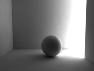
Global Illumination
finalRender can be used to calculate the indirect light distribution in a
scene. The Global Illumination (GI) process is started once all the direct
illumination has been calculated; this includes effects like caustics and
volumetrics. Each rendered pixel will be analyzed for an amount of diffuse
light. When the GI pass detects a rendered pixel needs additional infor-
mation, a diffuse amount of light is added to the pixel. Light is calculated by
bouncing it around the 3D scene. The amount of light transport and the number
of light bounces can be freely adjusted in the menu options offered by
finalRender. Remember that it's the materi- al itself (the surface properties
of an object) that determines its light distribution in a scene. Brighter
materials like white or yellow will not absorb as much light compared with
darker surfaces.
|
Standart |
GI render with
FR |
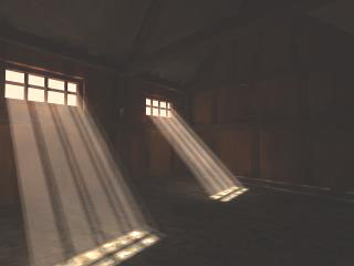
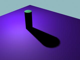
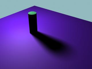
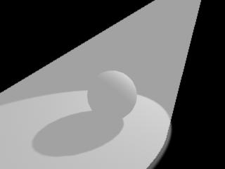
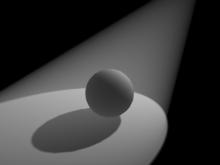
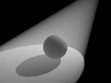
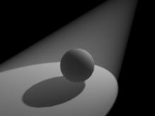
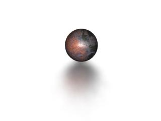
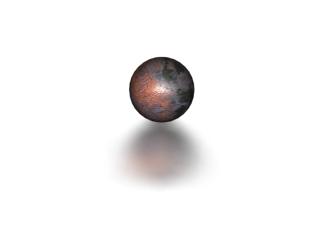
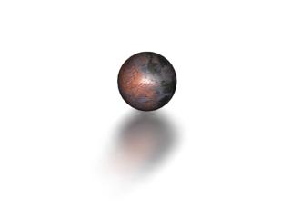
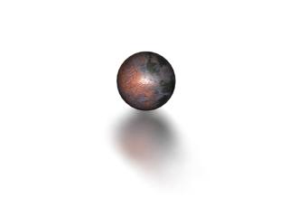
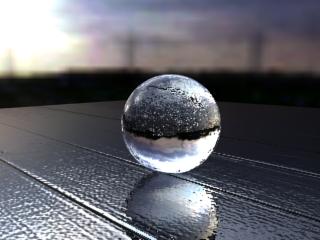
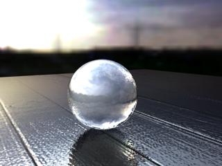
The images above of identical 3ds max scenes couldn't be more different. The
second shows the dramatic impact a Gl-rendering has. Both images have the same
camera and the same lights but are rendered with different methods. In the GI
image you can see how the light bounces around the corners, also notice the
soft and diffuse shadow cast by the sphere. It's pure indirect illumination
that's causing this soft shadow, not direct light. This scene will be used
throughout this manual to explain how GI is calculated by finalRender. The file
is called GI-Classic.max and can be found in the Global Illumination folder of
your original finalRender installation.
Why Global Illumination ?
finalRender creates photorealistic images by recreating natural light levels
found in a 3D scene. The lighting simulation uses advanced raytracing
techniques to compute the illumina- tion values- the amount of light each
surface receives or emits. There are two competing rendering technologies for
light simulation, one is Global Illumination & the other is called
Radiosity.
Radiosity uses a different approach to calculate and simulate light. It is
geometry dependent, so it needs to subdivide meshes as its algorithm decides,
this usually results in extremely high memory consumption. Even though there
are other drawbacks with radiosity renderings, it is thought that radiosiry is
more accurate when distributing light in a 3D scene. As Raytraced Global
Illumination calculations done by Radiosity are so different in their core, you
might expect different results in the rendering. In fact, the visual results
you get out of either ren- dering methcjd would be identical because both methods
use a physically correct approach to distributing light in a 3D scene.
Nowadays however, Global illumination has become accepted as die only
reasonable method to render physically correct light distribution. An advantage
GI has to offer is its unlimited scalability of the rendering process itself.
With other rendering methods each cal- culation is dependent on a previous
result. This isn't the case with finalRender as everything may run in parallel,
so more processors will accelerate the rendering process. These are a few of
the reasons why finalRender has chosen a raytracing approach to Global
Illumination.
How does it work?
finalRender uses an ultra fast hybrid raytracer to render Global Illumination
images. Any 3ds max scene may be used for a GI rendering. The scene is analyzed
and compiled into an "MSP-Tree" that acts as an efficient data
structure for the raytracing process (determining which surface a ray
intersects). Without using an "MSP-Tree" or similar sorting method
ray- tracing is not practical and would soon come to a crawl.
The lighting simulation engine of finalRender uses a new approach of multiple
rendering methods, like Monte Carlo and deterministic raytracing, to achieve
the best possible result in a reasonable time. All light calculations start
based on any of the rendered pixels (as seen from the camera); these are then
traced, as rays of light, backwards to their sources (other surfaces).
The light calculation can be divided into three main passes:
1.) Direct component the light hitting the surface directly
2.) Specular indirect component: light hitting a surface from other surfaces
3.) Diffuse indirect component:: light hitting a surface and being transmitted
with no directional preference
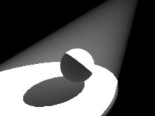
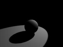
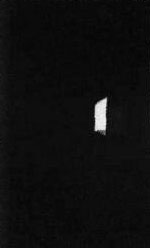
The direct light component
The direct light component consists of light hitting the surface directly from
a light source. No other light calculation is done with the exception of a
global ambient value that is added on top of the surface. All surfaces without
any direct illumination will be drawn with a pure black color. In the sample
illustration shown below, the areas that don't fall within the range of the
light cone will not receive any light.
Illustration GI-1
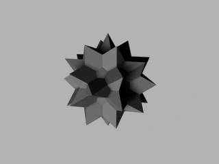
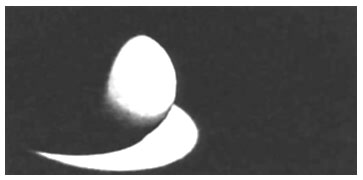
In the illustration below, an example of the direct illumination situation
shown above, there is no light bouncing off the sphere or the ground plane. All
the areas with no direct light (outside the cone) are pure black.
Illustration GI-1a
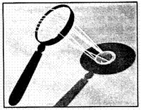
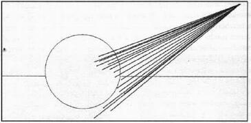
Caustics: The perfect indirect light
The specular indirect component consists of light hitting a surface from other
surfaces or light sources being reflected off or transmitted through surfaces
in a directional manner. Such perfect specular light transport is handled by
finalRender through an independent photon- tracing pass. This light transport
is calculated by shooting extra rays from each light source and then simply
redirecting the rays in the appropriate reflected or refracted direction (see
illustration to the right). Along each ray and its bounces (secondary rays) the
energy is collected and stored in an advanced 3D photon database. This
technology can very efficiendy calculate physically correct light patterns
created by reflective or refractive surfaces or material properties. Caustics
are great to simulate transparent and refractive material properties like
crystal glass or optical lenses.
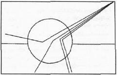
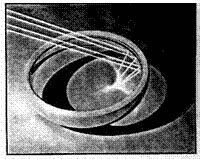
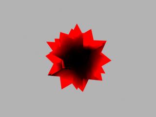
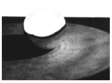
Illustration GI-lb represents a rendered example of the illustration above The
light rays bounce off the sphere and are reflected in a physically correct
manner onto the ground.
Illustration Gl-lb
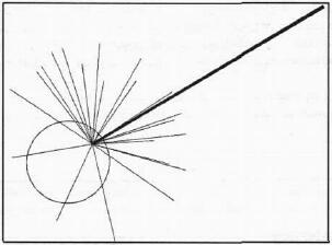
Total diffuse and indirect illuminations
The diffuse indirect component consists of light hitting a surface and being
reflected or transmitted with no directional preference (totally diffuse). The
nature of this component requires that hundreds of directions be examined in
order to make a reasonable
Illustration GI-2
Global Illumination is one of the most expensive light simulations; an average
of 3.1208 (3.12E08) rays have to be sent out to calculate a good light
distribution in an average 3D scene. This number could easily go up by a factor
of 1000 depending on the type of scene and the amount of indirect light that
had to be calculated! To measure the light level at a specific pixel (shading
point) in an image, lots of rays have to be sent out from the surface of each
object. The illumination level at such a point is only accurate when there are
enough rays shooting in all directions. finalRender uses an advanced
hemispheric dome of random rays to collect the surrounding illumination.
This still isn't enough to generate a nice image- there is more that must be
done! We described the first hit only. Each of the individual rays created by
the first hemispheric ray bundle will create another on impact with a surface,
then a new set of hemisphere rays has to be calculated. And this is how the
avalanche can start, let's say the first pixel creates 512 extra hemispheric
rays, each of the 512 secondary rays will also create another 512 rays and so
on.y
System related restrictions
Global Illumination will help you in getting better and more realistic images.
However, be warned that Global Illumination is not the "one button"
solution everyone is dreaming of.
The amount of rays plays an important role in achieving believable image
quality. A reason- ably high amount of rays must be sent out to get a good
overall illumination calculation. Sending out more rays results in a more
accurate illumination calculation, usually resulting in better image quality.
However, it is trivial to say the amount of rays is the only reason for
realistic rendering results. One technical shortcoming is the way in which
light is detected in a scene, diis is common for all GI based Tenderers, including
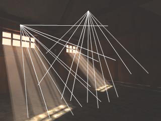
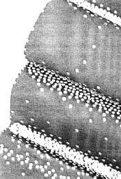
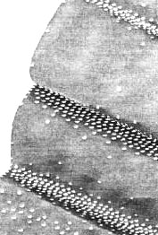
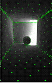
finalRender. Illustration GI-3a shows a stripped-down version of the light
detection as it happens in finalRender.
|
Illustration
CI-3 |
|
Illustration
GI-3a |
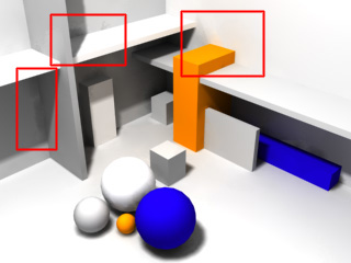
In illustration GI-3, two shading points (pixels in the image) are visualized
with some of the hemispheric random rays. To avoid confusion only the first ray
level is displayed, as each sin- gle hemispheric ray creates another set of
hemispheric rays and so on. As you can see in GI-3a, the initial rays are shot
from the ceiling and from the wall, neither is able to detect (see) any light
in the scene. Perhaps some of the secondary rays might reach those areas in the
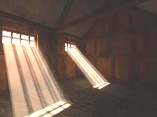
scene but the result probably won't be good enough. The only areas in this
scene that might be used as a source of indirect illumination, are the small
lit areas on the floor (from the sunlight through the windows). In relation to
the whole room, the lit area is very small to serve as a proper GI source. To
solve this problem the amount of hemispheric random rays must be increased by a
huge amount. This is just a "natural" behavior of the rendering
technology; compare this to mother nature, she would send out 1000 trillion
rays and even more Photons to solve the lighting situation! Also, remember
Global Illumination works the opposite way to direct lighting- light is
detected and collected in a scene rather than created in the direct light pass.
The Curvy Surface Problem
Besides the light detection and collection challenge in a 3D scene, there are
other challenges Global Illumination has to conquer. Many Radiosity or Global
Illumination systems are very "picky" when it comes to high polygon
counts, render rimes can explode by enormous factors. finalRender uses an
advanced method to calculate Global Illumination, which isn't so dependent on
the polygon count in a scene. finalRender is extremely responsive to the
surface properties of an object. Flat non-curved objects are treated very
efficiently by finalRender. A flat plane with 50,000 polygons will be treated
by the Global Illumination engine as if it were an object of only 12 polys.
However, as soon as you start to create some displacement on the surface the
problems are about to begin with render times. Note, that it isn't just the
fact that the surface is displaced or bumped- only when the bumps or canyons
are "near" to each other will the optimization algorithm be fooled in
some situations. As we mentioned before Global Illumination is all about
diffuse light bouncing around. Now try to imagine that a ray is
"trapped" in a little canyon. When the ray first enters the canyon
perhaps 512 (MC-Rays) rays are created and those 512 rays are trapped as they
hit the other side of the canyon and so on. The bad thing about this is that
those rays are useless as they will not find any important light values in
those canyons. It isn't possible for the algorithm to know if certain canyons
should to be rendered and others not. From the programming side there is no
difference between a corner in a room and a tiny canyon on a surface of an
object; both situations are identical, confined areas that need light bouncing
around.
Illustration Gl-3b
The solution to the problem, is clever user interaction, if you understand the
problem you might be able to avoid it. As you can see in the illustration GI-3b
the little canyons or bumps are real geometry, the sample points increase in
the confined areas to an unnecessarily high amount. In many situations you
would not expect to render "micro facet" inter reflections of light
on such surfaces. It wouldn't make sense to render with Global Illumination a
stucco wall created with real geometry. In this case you would need to control
the sample point placement based on the curvature of the surface. finalRender
offers a special function that performs exactly this task. If the surface
changes too quickly from one pixel to another, a sample point is usually
created automatically. In many situations this is fine, however in the case of
the stucco example we must avoid this behavior.
We strongly recommend that you watch all of the training videos that ship with
finalRender; they cover all the important steps of optimizing finalRender. All
of the training videos can be found in a folder called Training videos on the
distribution CD-ROM.
Control the surface
By using rhe finalRender global settings parameter Curve Balance, the creation
of sample points can be controlled in detail. If you compare Illustration GI-3b
with GI-3c, you can see there are less sample points in the curvy areas.
Shooting less random hemispheric rays will mean quicker render times.
Illustration GI-3c
It is a good idea to make heavy use of this parameter and even better to use it
on a per object basis. Curve Balance can be controlled globally so all objects
are affected, however more control can be achieved by changing th,e parameter
locally. The option to control local Global Illumination parameters can be
found under the GnalRcnder material settings. Remember when activated they will
overwrite the global settings. The finalRender material is where the option to
use local Global Illumination parameters is controlled from, remember when
activated they will overwrite the global settings. Using this method you can
set a different curve balance for each material in a scene. For example, a 3D
model of a sculpture might need a different sample point density than a model
of a roof in the same scencl Each object in the scene with a finalRender
material is available for this kind of fine-tuning.
Good news, light is scattering!
As mentioned before, light detection can be a difficult task and it's an
unwritten law that increasing the amount of rays will increase the render time.
GnalRender uses a physically cor- rect approach to distribute and detect
illumination levels in a 3D scene and this includes such phenomena as light
scattering caused by volumetric effects. So another source to gather
illumination levels in the previous sample scene is the volumetric light beam
itself I finalRender can respond to volumetric effects in a physically correct
way, so bright volumet- ric effects are able to emit light into their
surrounding area.
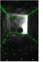
To solve the light detection problem in this scene, the amount of hemispheric
random rays was increased and the volumetric beams taken into account. The
result may be seen in the illustration GI-4. As you can see, the light
distribution in this scene is now much more realis- tic with all the physical
phenomena taken into account. The light bounces off the ground and the
"dust particles" also scatter the light into the room.
Illustrarion GI-4
Optimizing a Global Illumination calculation
As soon as you enter the world of GI you will find all of your thoughts
concerned with "How can I make it render faster?". Here we describe
some of the problems & solutions that can occur when working with GI. Very
often the solution for better cleaner images with GI is to simply to increase
the amount of rays in a scene. This solution isn't acceptable for most users
because processing power is still an issue. The only way to get around long
ren- dering times is a good understanding of the fundamental concepts and
methods used to optimize finalRender.
To get the best possible results with the minimum amount of rendering overhead,
the ren- dering engine determines "important areas" and less
important areas in a 3D scene. In gen- eral terms less important areas will
show a lower density of sample points (which are used to send out the
hemispheric random rays) and this will result in a much faster rendering time.
finalRendc? ftffers several parameters to control the speed and quality of the
GI rendering process, the parameters can be divided into two sections.
1.) Overall Sample Point Density
2.) Adaptive Sample Point Density Control
Illustration GI-5
The illustration GI-5 shows an "unintelligent" GI sample point distribution.
All sample points (hemispheric random rays) are evenly spaced without any
respect of the geometry details. If you rendered this scene with finalRender it
would create too many unnecessary samples in areas where less points would
create the same result. Even worse, there are areas that need more sample
points to avoid creating rendering artifacts. A rule of thumb is that big flat
areas usually don't need as many sample points compared widi confined areas or
areas of high contrast, which usually need many more sample points. finalRender
uses advanced detection algorithms to distribute the GI sample points on the
surface of objects. By applying this function wisely there is a lot of
potential to speed up rendering times. A world-case scenario for placing sample
points is when every pixel needs to create hemispheric random rays, regardless
of any conditions that might apply. You want to avoid these kinds of
situations, if you have to render a scene under such circumstances finalRender
offers a brute force method of the
Reduce the amount of sampling points
One of the most important Global settings in finalRender is Balance%, this
parameter controls the balancing between the Min. Density and Max. Density. A
balance value of 100% would mean that every shading point (pixel) will create
hemispheric random rays. All other values be low 100% will balance the density
of sample points towards the Min or Max density. You want to avoid a Balance of
100%, as the render time and memory consumption could get quite high. The
density of sample points is dependent on the size of a 313 scene, scenes with
large dimensions need high density value, while scenes with small dimensions
are ok with lower values.
The overall sample point density in a 3D scene is controlled by two parameters:
Min. Density and Max Density. Min Density controls the minimum density of
samples that should be used on all surfaces, regardless of any adaptive rules
that might be applied. Larger numbers will create higher densities of sample
points in the scene. Min Density is usually used to control the density of
sample points in "flat" areas of a 3D scene. "Flat" means
not just those regions with no nearby objects but also those areas that show
less changes in illumination levels. Keep in mind that Min Density is not
restricted to those "flat" areas alone, it will also affect to a
certain degree the areas with higher densities.
Max. Density on the other hand controls the "near areas", those areas
with a high variance in the illumination level. You would find these areas in
regions where a shadow appears and also where two objects are close to each
other.
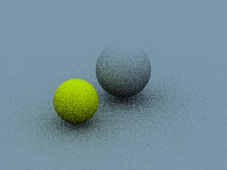
illustration GI-6
As you can see in the illustration GI-6, the distribution and density of
sampling points is now respecting the geometric properties of the scene
(compared to illustration GI-5). Corners now show a higher density than flat
areas. Look at the shadow area near the sphere, this are a shows a higher
density of sampling points than the surrounding "open" areas. This
distribution of sampling points is the preferred one, as those regions usually
create some sort of shadow this means that the illumination levels change much
faster.
finalRenders detection algorithm of these areas is usually very efficient.
However, it is possible that in some scenes the detection will not be as
efficient as in other scenes. This is not a mistake of the software, as there
are many variables that influence the distribution of Global Illumination
sampling points. An important thing to do to help finalRender work as
efficiently as possible, is the supply of a minimum amount of "first
level" detection. What does "first level" detection mean? The
Global Illumination process is started after the calculation of all direct
lights is done, the GI pass then starts to "search" for light in the
scene. Each sample point will create new rays that are sent out in a random
hemispheric dome manner. Those new rays are used to detect further light in a
3D scene. Now it should be dear that the number of sample points must be
reasonably high, so that the random hemispheric rays can detect light and other
objects nearby Sample points arc always created on the fly and so there is no
chance to do any corrections if an important sample point is missing. If the
distance between two sample points is too high (tow density) it might be
possible that an object lies "in between" the samples and so can't be
seen by the Global Illumination process.
illustration GI-7
|
Another indication of bad distribution (density) of sample points are artifacts in soft shadows! The Global Illumination rendering process creates real area shadows or soft shadows. These types of shadows are usually created in real world situations where there are multiple light sources or area lights (light boxes). Technically speaking this means that a point that lies in the shadow might "see" another fight source. The result would be a much brighter shadow than you would get it from a point light To detect such fine details with area lights or multiple |
|
light sources (other
surfaces bouncing light) a certain minimum amount of sample points is needed.
Illustration GI-7 is an example of how the shadow areas took when you don't
have enough sample points in a scene.
illustration GI-8
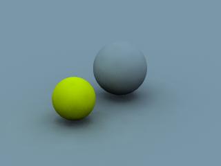
Illustration GI-8 is how the shadows should look like when the amount of sample
points is high enough to detect all the details.
Always make sure that a 3D scene has enough minimum sample points, this is
usually controlled by the Min Density parameter. Don't think that more is
always better, usually the "mid" values create the most impressive
images with "first rendering time.
Other ways of optimizing
One could say "Raytracing in general, is a time consuming process"
but regardless of any speed issues with raytracing, it is still the only
rendering method available to represent red world effects like reflections or
reflections.
So what is the problem with raytracing?
All raytracing software faces the same problem, regardless if it's a $5000
package or a $50 shareware raytracer. Shooting the rays is the core problem, be
cause each ray that is sent out into a 3D scene has to be tested against an
intersection with a triangle. The computation of these intersections is very
time consuming, especially if the software had to check each ray against all
triangles in a scene. An increased amount of triangles in a scene will result
in an increase of computation time. When the software manages to get the
intersection done properly and fast, the nest problem is the calculation of the
illumination level at the intersection point. This is called shading and
usually different shaders take care of the surface illumination. Another
important time factor in a scene is the type of shading equation because.
Careful research and development has been done to solve the first problem of
raytracing in finalRender. The core module of finalRender that handles the
intersection besting with 3D objects in a scene is called an MSP-Tree. A
proprietary bounding volume collection algorithm is used to effectively
optimize the ray intersection testing in finalRender. Explaining the algorithm
or method in detail is be yond the scope of this manual, but some basic
knowledge about this optimization method is helpful in using its advantages.
Before the actual rendering starts, all 3D objects will be collected as a big
list of triangles. Each luster of triangles is bound by a volume for faster
testing. In general, a ray intersection test against abounding volume is much
faster than testing against all triangles. If a ray does not hit abounding
volume, all the triangles within it do not need to be processed at all
finalRender has two controls for the MSP-Tree, one is the sorting depth for
nested objects/triangles and another is the amount of triangles per bounding
volume. Both parameters affect the memory consumption and processing speed of
the render. Remember that the default settings are fine for most of the scenes
you will create in certain situations though it might make more sense to adjust
one 12512y2416m or both of the parameters. Note that increasing the depth will usually
result in more memory consumption and sometimes the render time will increase
as well. Increasing the amount of triangles per bounding volume might decrease
the memory consumption, but it will also increase render time in certain
situations. The MSP-Tree algorithm is a highly dynamic and adaptive process
that is difficult to predict. There are so many variables that influence the
bounding tree generation no one can foresee the final result and performance
for an optimized scene.
Conclusion
finalRender is a complex raytracing system and it covers all the areas of
modern computer graphics. Illumination, atmospherics and advanced distributed
raytracing effects are only some of the areas that are supported by finalRender.
So how should you, a new user of finalRender start exploring the world of
advanced ray tracing. Well it's always a good idea to start with the tutorials
that you are interested in, some may understand better the training videos that
ship with finalRender, also try to work through all the chapters in this
manual, along with the rich set of example scenes of finalRender features for
an in depth understanding.
To make things easier here are some initial tips and tricks that will help you
in avoiding the typical pitfalls a new user may run into.
Analyze the scene ou going to render.
When it gets to illumination or material adjustment of a scene try to split it
into as many parts as possible. What is causing direct light (Sun, light bubs
etc.) and what is causing indirect light? What is the balance between direct/indirect
light?
Avoid high variation in illumination levels
Detecting illumination levels in a 3D scene can be quite tricky. To avoid this
problem add as much direct light as possible. Also don't be afraid of using a
light gray ambient value for the Final GI rays.
Reduce the intensity level of the direct light amount when using GI
Global Illumination takes care of the indirect illumination effects in a 3D
scene. This will usually result in brighter scenes as if you were using direct
light, bear this in mind when setting up a scene with many direct lights.
Make heavy use of the optimization tools
It is essential to understand how finalRender offers many speed optimizations.
Some of the tools need user interaction and some don't. It is always better to
assign separate finalRender materials to multiple objects, this gives you full
control of all raytracing features on a per object/material level.
Use the Internet, if you can't
Do you have Internet access? Try to search the web for Global Illumination or
Raytracing articles. Many of the descriptions you can find are relevant for
finalRender. Also www.finalRender.com serves as a source of information along
with great sample images. It's always a good place to take look at.
New finalRender Light Types
LumaObject is now a core part of the finalRender raytracing system for 3ds max,
it offers additional light types to the standard set of lights. Some of the
light types can be used to turn any 3ds max geometry into a light emitter and
so allow the simulation of a real area light. You can also use these same light
types to simulate or fake Radiosity-like effects by turning any 3D geometry
into a light-reflector. Light may bounce around in a 3D scene and areas usually
dark or even black will receive illumination, as you would expect from in a
real world situation.
|
In addition to geometry based area lights finalRender also has a real Cylinder type light and a Particle based light type. All of these light types can be used to enhance the realism of a render or to add unique special effects finalRender light types offer realistic area lights & radiosity effects in a very effective and efficient way. In this chapter we discuss how to use these new light types. |
|
Radiosity with finalRender Object Lights?
illustration LO-1
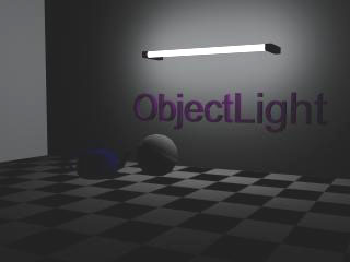
First lets concentrate on the geometry based light type called fRObjLight It's
the most powerful light type that can be used in many situations In the
illustration above, you can see a Radiosity-style image. finalRender is a Global
Illumination system, why would you want to use it to take radiosity if it can
render such images with much more realism. The reason is that this image took
only 10 seconds to render, compared with minutes for a GI render, add 1000 of
frames to an animation and you have a good reason to take GI!
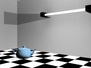
The finalRender fRObjLight light type is used in the illustration LO-1 in
several ways. First of all the neon tube is emitting light to the extents of
room from the total area of the tube. Ibis is hard to create using the standard
scanline rendering system so a fRObjLight is used on the geometry (the neon
tube is modeled) to turn it into an area light. The next major effect
distinguishable in the Illustration LO-1 is the reflection of the shades from
the teapot. This is also nearly impossible for a scanline rendering system to
achieve, one would need a processing intensive Global Illumination calculation
to get the correct look.
In the Introduction to finalRender chapter we were talking about the different
rendering methods offered by various software packages. LumaObject or
finalRender object lights in contrast to other common rendering methods like
Radiosity or Global Illumination, try to simulate real lighting situations by
offering the ability to bounce fights off any surface in a 3D scene. Like in
Radiosity or Global Illumination every surface is taken into account for this
calculation and every surface is handled in a similar way to a light source.
However, finalRender light objects are rendered in the "direct" light
pass and so the rendering speed for this effect is much more optimized. The big
secret about this incredible rendering speed is the use of many highly
optimized virtual light sources scattered on every surface of an object. Those
virtual lights can be turned on in two different ways. The first option is to
turn them on by a constant amount, which is calculated from the surface
(mapping) of the object itself, in this case you would get a realistic area
light. The second option of a fRObjLight is to make the virtual lights react to
other finalRender object light sources that shine on (or near) the surface of
an object.
What's the big deal about Object Lights?
With Object Lights finalRender offers an approach to mimic Global Illumination
or Radiosity effects in order to offer practical rendering speeds and
flexibility Object lights share the same elementary methods as Radiosity or
Global Illumination. The strongest argument to use finalRender object lights is
for animation. As finalRender object lights are calculated in the direct
illumination pass, based on a fixed non-stochastic method, it's much quicker to
use this type of illumination for animation. Currently none of the Global
Illumination or Radiosity rendering systems is able to render animation in a
reasonable amount of time. On the other hand, finalRender object lights have no
restriction at all You may animate any aspect in jour 3D scene regardless if an
object is moving or a light color is changing or a mesh deforming, all this is
possible without any rendering errors.
How to use finalRender Object Lights
To assign a finalRender Object light effect to a specific object in a 3D scene
our AABS (Automatic Analytical Binding System) method is used. finalRender
object lights are not simple lights like spot lights or omni lights, a 3D mesh
is needed to define the area of light emission, but how do you visualize such a
light object? A spot light for example, has a visible light cone and a target
point but how would you know where the light shines from a teapot as or a wavy
surface? finalRender object lights are implemented as "shapeless"
helper objects (a little yellow "X" in the scene). This
implementation avoids thinking about the light as a specific shape or position.
The light helper object is used to store all settings and parameters. So, how
do you tell that a light helper is affecting a specific object: This is exactly
where AABS can help you? Keep on reading to learn how it works.
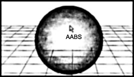
What is AABS?
Whenever you create an object light helper, an automatic analyzing process is
started by tracking the mouse movements in a 3D space. The area below jour
mouse cursor is analyzed before you release the mouse button. Any object type
that maybe suitable for such an operation is indicated by a cursor change to
the letters AABS. No other user interaction is needed to assign an object light
effect to any 3D mesh. As a result of the AABS method, the object clicked on,
is added to the list of final render object lights.
What else can be assigned via AABS?
For example, if you want to turn a particle system into a thousand different
glowing lights you would use. AABS to control the generation of the effect. If
you click the fRPartLight helper onto a particle system, AABS will
automatically take care of the effect. Every particle is auromatically turned
into a highly optimized point light. No further assignment or selecting is
needed.
What do the little pins do?
SPi-Technology
![]()
Another cebas workflow enhancement for 3ds max4 is called Selective Parameter
Instancing (short: SPI).
SPI allows to have only selected parameters shared between other objects of the
same type. When there are multiple fRObjLight helpers in a scene, each single
parameter maybe connected or instanced with others. This functionality is
similar to the parameter wiring function of 3ds max4. The only difference
between the functions is the easy of use of SPI, to enable a parameter
connection (wiring) with 3ds max4 you would need at least 8-10 mouse clicks
while SPI does it all in one single mouse click!
So how does SPI work?
Notice the little pins (Pin Image) to the right of each parameter. If you
"pin down" a parameter it indicates that you want to share this value
among all other objects of that type.
Example:
A scene has 3 fRObjLight helpers. Those
helpers are used to rum several walls in a room into light reflectors. You do
not want to have to control each wall (each helper object) on its own. The
amount of fight bouncing should be a "global" setting for all
fRObjLight helper objects. To achieve this you need to "pin down" the
pin icon right next to the Multiplier value of the fRObjLight. Repeat this step
for each of the helper objects. The first parameter in the first helper object
that was pinned down will act as an initial master. All following "pin
down" operations will automatically set the Multiplier value to the same
amount as set in the first (master) helper object.
We believe SPI offers a real advantage and will help you control your scenes
much faster and easier than before.
Object Lights and Volume Effects
finalRender object lights treat volumetric effects like any other light does.
Compared with 3ds max LumaObject renders volume lights up to 4 times faster.
However, keep in mind that as finalRender object lights are real area lights it
makes it extremely complicated to render volumetric for them. Imagine a light
box as a volumetric light effect, the whole area of the light box would need to
create light beams. You expect to see one big area light beam coming out of the
light box surface and not 100 individual tiny beams, finalRender easily handles
such complicated volumetric effects.
The following pages will explain in detail the parameters of finalRender object
lights. If you are interested in how to set-up object lights check out the
tutorial chapter that covers many of the common tasks.
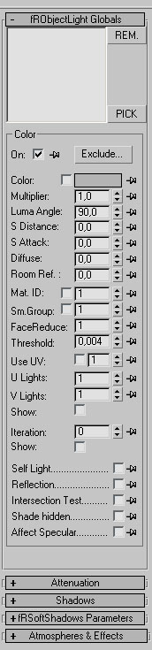
The fRObjectLight rollout menu
Selection
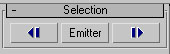
Object lights are implemented as helper objects and this means that each
different light effect may have its own fRObjLight helper. Many objects in a
scene may cause some workflow problems when you want to change multiple
settings in one go. The selection rollout menu has three buttons that help you
to organize and access the fRObjLight helpers in a very efficient way. To
wander through all object light helpers in a scene you may use the Next or
Previous buttons. There is no faster way to switch between different object
light helpers. You may even press the Emitter button to get the relevant light
emitter (the mesh) activated. This works without leaving the modify mode or
calling a different dialog (e.g. Select by Name). Right-click on each button is
also possible to get a list of all available helper objects or emitters in the
scene. A double-click none of the entries will jump directly to this
object.
Globals Rollout Menu
Pick and Remove
|
Besides
the AABS method described in the previous chapter, you can also use a
standard 3ds max pick operation to assign the object light effect to multiple
3D objects in a scene. To do this, press the PICK button and select one
object or use the "Select By Name" feature of 3ds max to select
multiple objects in one go. The selected objects will be added to the list.
To remove one or many objects from His list use the REM. button. All objects
selected will be removed. |
|
Exclude/include
This function works exactly the same way as regular lights in 3ds max or 3D
STUDIO VIZ. If you press this button you will get a new dialog identical to the
exclude/include dialog 3ds max or 3D STUDIO VIZ uses. It is a very good idea to
use include/exclude lists in a scene. Depending on how complex the scene is,
you may save up to 50% rendering time just by using an exclude list for light
objects. See 3ds max or 3D STUDIO VIZ manual for more details about using
exclude lists for lights.
Color Swatch
![]()
The color parameter for finalRender object lights behaves a little bit
different when you compare it to the color parameter for standard lights. When
unchecked, the light color is taken from the object's surface (material). A
self-illuminated material will control the light intensity via the amount of
self-illumination. If you check this color switch the light color becomes the
value set in the color swatch tight next to the checkbox. The color can be set
as usual via the standard 3ds max color picker.
Multiplier
![]()
As you already know it from standard 3ds max lights, the multiplier spinner
controls the intensity of the light source. A value of 1.0 will light a scene
with the original intensity and color of the light. 1 value of 0.5 will only
use half of the initial color intensity. You may also use negative multiplier
values to get "negative light" effects, so instead of making the
scene brighter the scene gets darker.
Luma Angle
![]()
Luma Angle controls the angle of the light emitters on the object's surface. finalRender
places on each triangle of the object a special highly optimized "Virtual
light" source. Lima Angle lets you control the spreading of the light cone
of all light emitters. See diagram below
illustration LO-2
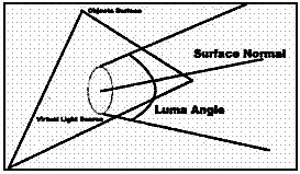
As you can see in illustration LO-2, the angle value represents the opening of
the light cone. A value of 180 degrees will generate the widest possible angle
for a light emitter. Keep in mind that this value is used per "Virtual
light" emitter!
Tip:
For most realistic Radiosity style effects you should use wide angles
(>60o). This will make sure the light reaches even the farthest coiners of a
scene. It is not recommended to use volumetric effects with wide Luma Angle s
as the rendering times maybe come very high. Smaller angles increase
calculation speed, but will show the spotlight nature of finalRender object
lights.
S Distance
![]()
is distance automatically controls the widening of the Luma Angle dependent on
the distance to an object.
Take a took at the illustration be low.
Illustration LO-3
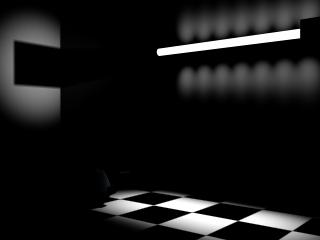
Illustration LO-3 shows a problem that you usually want to avoid. If you
examine the floor you will recognize that there are no spotlight cones visible.
In contrast to the floor the wall shows in a very precise way the spotlight
nature of finalRender object lights. This is because the Luma Angle is set to
45 degrees. Because of the small distance between wall and neon tube the light
doesn't have enough distance to blend together. One way to solve this problem
would be to increase the Luma Angle of the light emitter, but then you
sacrifice render time. Instead the S Distance value is used as a solution. When
the distance to an object decreases the Luma Angle will automatically get
bigger, so this will result in * mo m diffuse natural looking light.
Illustration LO-4
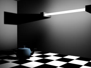
Illustration LO-4 uses the S Distance value. When you compare the two
illustrations you will see that LO-4 has a much smoother result in the
"near" areas making it impossible to tell where the "Virtual
lights" are placed on the surface of the tube.
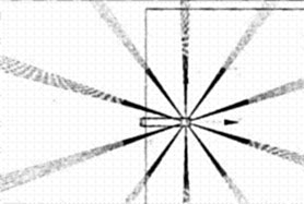
How do you know the distance to a light
emitter?
It would be impossible to tell the distance to the nearest object by eye,
finalRender however offers visual feedback on where it starts to increase the
Luma Angle up to 180 degrees. Blue rays coming out of the light emitters show
the areas when finalRender will start increasing (decreasing) the Lima Angle
value. This is usually done in a linear way. When a blue ray hits an object it
will start increasing the Luma Angle automatic ally. The length of the blue ray
defines the time it takes the virtual light to reach an angle of 180.
Illustration LO-5
S Attack value
![]()
S Distance is used to get smooth illumination on areas where the surface of an
object light is near to another surface that receives it's light. However, the
S Distance will only change the angle of the virtual light in a linear way and
this might look a little strange if an object moves around or is deforming very
fast If the linear took is wrong you can control the speed of angular change of
the S Distance (how fast Luma Angle win be increased) by using S Attack.
As described in S Distance, finalRender increases the Luma Angle value up to an
amount of 180 degrees in a linear manner. The length of the blue ray (and this
is the S Distance value!) is equal to the inverse f the Luma Angle. In an animation it maybe too obvious
that the Luma Angle value is increased and it may appear unrealistic. To get
rid of this "mechanical" took you an use the S Attack value. It controls how fast the
Luma Angle is increased by distance. Higher values will result in a faster
change (exponential) of the Luma Angle value.
Diffuse Value
![]()
Because of its "spotlight" nature, finalRender usually can't simulate
real diffuse lighting in a Radiosity manner, however, clever programming can
create nearly the same impression. If you increase the diffuse value above aero
light will "spread" away from the original vector of each light (the
face normal). This makes it possible to bend light over an object's edge, as
occurs in natural lighting situations.
Illustration LO-6

Illustration LO-6 is rendered with a Diffuse value of 0. As you can see, the
left corner of the room is very dark and the left wall shows a dark round spot.
This is because no light can reach these regions.
Illustration LO-7
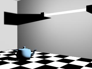
Illustration LO-7 shows a more diffuse look to the lighting. Even the comers of
the room receive some light and the complete scene looks much more believable.
This picture uses a Diffuse value of 0.5.
Tip.
Take care in using the Diffuse value with objects defined as light reflectors.
These will receive more light and so the overall reflection intensities will be
higher. Your scene will look too bright, a solution to this is to reduce the
Multiplier value of the object lights.
Room ref.
![]()
A widespread problem among artificially generated images is the lack of overall
light distribution in a scene. The Room Reflection value increases the lighting
of all objects in a scene, like an ambient "background" light level.
By increasing this value, you are even able to illuminate faces of an object
from the backside! This is how you can simulate indirect lighting! However,
don't confuse this with the ambient light feature of 3ds max, which works globally
and is not influenced by different lights in a scene. LumaObject does room
reflection calculations based on the selected light emitter. This approach
generates much more believable diffuse lighting. See the pictures LO-8 and
LO-9.
Illustration LO-8
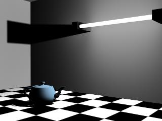
Illustration LO-9
Material ID
![]()
Check this switch to use a specific material ID to generate light emitters on
an object's surface. You can select a material ID by using a multi/sub object
material. With this feature you are able to decide which part of an object
should light the scene. For example, if you have a lamp that is one single
object with different mull/sub materials you can easily choose which part
should shine by selecting the material ID.
SM Group
![]()
Using smoothing groups is another way to indicate which pan of an object should
emit light. In contrast to the Material ID option, smoothing groups are a
geometry based selection method. Usually different parts (elements) use
different smoothing groups. With this feature you are able to let only round
(smooth) parts of an object emit light.
Face Reduce
![]()
Usually when you attach a fRObjLight helper to an object finalRender will
generate a "virtual light" source for each single face. This behavior
might be close to real physics but if the object were made out of 100,000 faces
it would take hours or even days to calculate such an object YOU wouldn't see
any difference to an object using only every second (or even any 20th) face as
a light emitter. To reduce render time use this value to reduce the creation of
light emitters on each surfaces. A value of two would me an every second face
acts as a light emitter. The preferred method to distribute the emitters along
the surface of an object is by UV mapping.
Threshold
![]()
finalRender turns a 3D mesh into an object light, it places a light emitter on
all surfaces. The color for each light emitter is calculated based on the
object's surface color . If you don't want to have virtual lights reated in dark are as. Threshold controls the cut-off
value at which a light emitter is generated on the object's surface. This value
represents the face intensity and all surface intensities below this value wont
reatea
light emitter. If you increase the value you will reduce the total amount of
light emitters on the objects surface.
Tip
This function plays a big role when you are going to use High Dynamic Range
Images on object lights. By treasuring the Non Clamped Color value you are able
to detect the real lights in the HDR image.
Use UV
![]()
If you check this switch finalRender will use the object's UV mapping
coordinates to place the light emitters on the surface. The light emitters are
equally spread over the 2D UV space. You can control how many light emitters
are created by changing the U Lights or V Lights value.
The object must have a UVW mapping modifier or be created with "generate
mapping coordinates" turned on!
Tip
Using UV mapping should be the preferred method for Luma objects in your scene.
If's the most flexible and optimized way of generating light emitters for the
object.
U Lights
![]()
This value controls the number of light emitters in the U-mapping direction.
Light emitters are equally placed along the 2D UV space. This value enables you
to control the absolute amount of light emitters for the selected object. If
you multiply U Lights by V. Lights you get the overall amount of light emitters
place don the surface of the object.
Tip
You must check the Use UV option in order to use this value. Try to use as few
emitters as possible! This will help you get the fastest render time. To compensate
for missing light emitters, you can increase the Luma Angle value to get a more
diffuse light.
V Lights
![]()
This value controls the number of light emitters in the V=mapping direction.
Light emitters are equally placed along the 2D UV space. This value enables you
to control the absolute amount of light emitters for the selected object. If
you multiply U Lights by V Lights you get the overall amount of light emitters
placed on the surface of the object. You must check the Use UV option in order
to use this value.
Tip
Try to use as few emitters as possible! This will help you speed up render
times. To compensate for missing fight emitters, you an increase the Luma Angle value to get a more diffuse
lighting.
Show UV
![]()
If you check this button, the light emitters are shown on the object's surface
as small red dots. This provides visual feedback of where the light emitters
are going to be placed on the object's surface and how many light emitters are
used for the object.
Iteration
![]()
finalRender object lights get their color and intensity values based on the
object's surface properties. For ex ample, if a self-illuminated material is
used, the surface of the object will act as a light emitter. The light color
for each "Virtual" light is based on the map applied to the object. A
self-illuminated blue-green gradient mapped on the object will result is an
area light of the same colors. Light reflector objects will also behave like
this they will reflect the light with the color of the surface of the object.
Iteration is used to control the quality of area sampling around the light
emitters. When a virtual light is created on the object's surface, the
intensity and color is defined by the surface color, which might not be the
correct one. If there is a black pixel in the map and all other pixels around
are white, the virtual light would still use black as color/intensity. By
increasing the iteration amount a bigger area is used to collect the colors and
intensities form the map on the surface. The Iteration function is great when
you do not want to increase the amount of virtual lights on the object's
surface.
Tip
Area sampling is much faster than creating more lights on the surface and most
of the time the result is the same or even better. We recommend that you use
iteration most of the times and especially on objects acting as light
reflectors.
Illustration LO-10 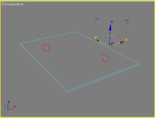
Image with iteration valu = 0
Illustration LO-10 shows an object that has four fight emitters in total. To
make this object reflect light you would usually use more virtual light
emitters. In this situation you would get only a light bounce when an emitter
is hit. A much more efficient way would be to increase the iteration count.
This extends the single light emitters and so it covers a bigger area it can
react on. See next illustration.
Illustration LO-11 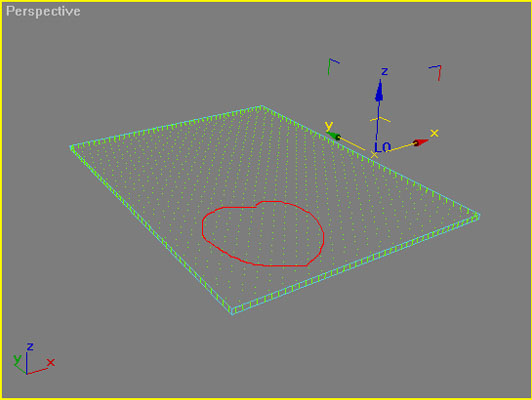
Image with iteration valu = 20
In Illustration LO-11 you see that the whole object is "hot" now.
Even when a light cone only hits the outer edges of this surface it will start
shining fight back. If the surface were a color gradient, the correct mixture
(average) of the colors would be reflected from this surface.
Show (Iteration)
![]()
Check this button to get a visual feedback of the iteration area. finalRender
takes into account the increased area to calculate the color or the active area
of a Luma object and is shown as little yellow dots. See Illustration LO-11.
Self Light
![]()
If you check this button the attached object will emit fight regardless of its
self-illumination value. This an produce paradoxical scenes where the object is dark
(near black), but illuminates its environment. When off the illumination
intensity will be taken from the self-illumination amount of the map.
Tip
You may also use the output rollout menu in the bitmap section of the material
to increase the RGB level to numbers way above 255! This is great when you want
to create re ally bright light sources.
Reflection
![]()
The incredible fast rendering speed you can get from object lights has
drawbacks that are caused by the method of how the area lights are calculated.
Multiple object lights will not shine (bounce) light onto each other, if
finalRender alb wed this you would end up creating real Global Illumination. To
achieve at least one bounce between multiple object lights activate the
Reflection checkbox. When checked, each object light will be able to shine
light onto other object lights in the scene.
Intersection
![]()
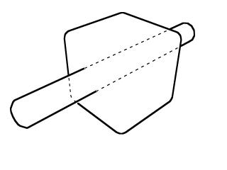
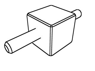
Object lights do not support real area shadow creation or self-shadowing.
However, finalRender offers a unique method of doing a self-intersection test
with object lights. Light rays that would be blocked by the object creating
them aren't sent out into the scene. Imagine you have a box with an open top,
only the inside of this box is turned into alight emitter. When intersection is
turned on, all the light will come out form the top only. When off the light
will spread through the walls of the box as you can see in Illustration LO-12.
Illustration LO-12
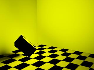
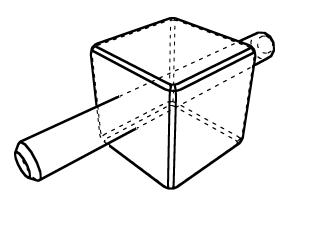
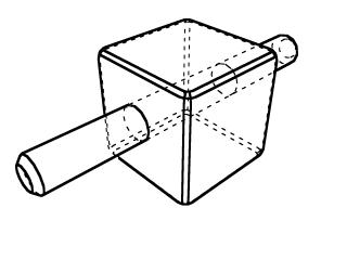
Illustration LO-13 has intersection testing turned on. All light beams
intersecting with the object light itself are switched off automatic ally. They
are not actually switched off but faded to black. Note this only works with
self-intersection and not with other object lights!
Illustration LO-13 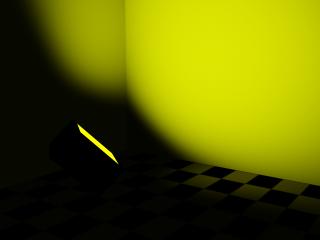
Shade Hidden
![]()
Standard lights created by ads MAX or VIZ are not visible. When you create a standard
omni light, only its effect (illumination) is visible and not the object
creating the fight. fRObjLight objects are visible lights by default. The
object or surface creating the area light effect is a standard geometry and so
it is also visible to the rendersr.
Affect Specular
![]()
Area lights usually do not create any specular highlights on surfaces. In fact
the problem of area lights creating specular highlights in ads max is more
related to how shaders like Phong or Blinn calculate such highlights. When
Affect Specular is turned on, the shaders get an averaged point to calculate
the specular highlight.
Attenuation
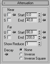
In nature a light beam reduces it's intensity by the distance traveled from the
light source. The intensity is reduced by the square of the distance traveled.
This dialog is identical to 3ds max or VIZ own attenuation dialog for light
objects.
Reduce
The reduce parameter is specific to fRObjLight objects only. An attenuation
range vector is created for each light emitter, this can easily end up in
thousands of lines being drawn. To show only every Nth vector, use the reduce
value. A value above 1.0 decreases the amount of rays drawn.
Cast Shadows
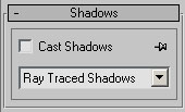
This dialog is also identical the 3ds max dialog for shadow casting lights.
However, finalRender creates a special kind of shadow caster. In contrast to
standard 3ds max/VIZ light objects, finalRender creates a shadow casting omni
light that resides in the center of the light object. This special shadow
caster creates six shadow-casting lights - one for each direction. When you use
a raytraced shadow an averaged center point is used to simulate a point light
only for shadow casting. This is done for speed issues and compatibility
reasons as 3ds max shadow generators only support point lights.
Atmospheres & Effects
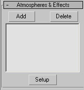
finalRender object lights also support atmospheric effects. The method to apply
a volume light effect is identical to the way you would do it for any other
light in 3ds max.
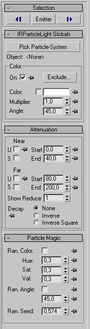
Particle Light Rollout menu
Particle systems are also supported in a very special way. The functionality is
nearly the same as object lights. When you want to turn particles into fight
emitting objects you just need to lick onto a, particle system emitter when creating a
fRPartLight helper. The helper object (the little X) snaps to Me center of the
particle system. This is the visual feedback that AABS was activated and
everything is "ok". You can also create the helper object by a simple
mouse click on the background of the modeling view port and then you may use
the Pick Particle System button to choose any particle system in the scene.
|
Selection Rollout |
|
Pick Object ![]()
If you do not like the -LUIS approach or if you want to change the assignment
afterwards, use the Pick Object button to pick a different particle system.
On/Off
![]()
This switch works exactly the same like other light objects in 3ds max or 3D
STUDIO VIZ. To switch off a light, uncheck this button. This value acts as a
switch only.
Exclude/Include (fRPartLight)
![]()
This function is identical to the one implemented in 3ds max or 3D STUDIO VIZ.
If you press this button you will get a new dialog identical to the
exclude/include dialog ads max or 3D STUDIO VIZ uses. Depending on how complex
the scene is, you may be able to save up to 50% rendering time just by using a
clever exclude list for light objects. See jour ads max or 3D STUDIO VIZ manual
for more details about using exclude lists for light objects.
Color (fRPartLight)
![]()
The color parameter for finalRender particle lights behave a little bit
different when you compare it to the color parameter for standard light objects
in 3ds max or VIZ. Check this color switch to make finalRender use the color
you have chosen from the 3ds max color picker.
Multiplier (fRPartLight)
![]()
The multiplier parameter controls the intensity of the light source for each
single particle light. A value of 1.0 will light a scene with the original
intensity and color of the light. A value of 0.5 will only use half of the
initial color intensity.
Angle (fRPartLight)
![]()
Angle controls the cover angle of the light emitters. finalRender will create
for each particle a highly optimized point light source. In contrast to a
standard point light you may adjust the cover angle each particle light should
have.
Attenuation
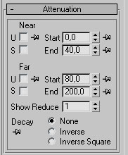
In nature a light beam reduces it's intensity by the distance traveled from the
light source. The intensity is reduced by the square of the distance traveled.
This dialog is identical to 3ds max1 or VIZ own attenuation dialog for light
objects.
Note.
The reduce parameter is specific to finalRender only. In the case of a particle
light only every Nth particle is shown with a attenuation volume.
Random Color
![]()
If you turn this switch on, finalRender will use random light colors for each
particle. This will ensure that no two particle lights look the same.
Hue, Saturation, Value (fRPartLight)
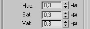
To get random light colors out of the particle system you need to adjust ho w
much the colors should vary. The base color is always the particle color or the
light color you select. The values you type in for Hue, Saturation and Value
are angles on the standard color wheel Higher values mean more variation in the
particle system, and also you an randomize each setting separately.
Random Angle
![]()
Another possible way to add some randomness to a particle animation is by
randomizing the Angle value. If you switch this button on, finalRender will
create random angles for each particle light. If you increase this value you'll
get more variation in the light particles.
Random Seed (fRPartLight)
![]()
The randomizer engine has to start some where to generate random numbers. If
you always use the same starting number and you have more than one particle
system using fRPartLight objects, they will all look the same! To change this
you should always use a different random seed number for each particle light in
a scene.
Cylinder Light 
Besides the object based light emitters, finalRender also offers a real
procedural area light implemented into 3ds max. The Cylinder Light is like any
standard light type. To access and create the new light type select create
lights and choose from the drop down list finalRender. This brings up the
finalRender light menu where you an create a new Cylinder Light.
A Cylinder light can be used and controlled like any other standard ads max
light. It is tightly integrated into ads max and it offers all the functions
and features of standard lights. In this chapter way will only cover those
features that are different to standard 3ds max lights, please check the ads
max online manual for more details about these standard features.
Cylinder Light Rollout Menu
Features like On/Off, Color, Multiplier, Exclude/lnclude, Attenuation, Shadows
and Atmospheres Effects are identical with the standard light implementation.
Every standard light source has those rollout menus and so does the finalRender
Cylinder light.
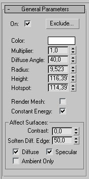
Diffuse Angle (Cylinder Light)
This value controls the "diffuseness" of the area light. It defines
the angle at which the light should spread out from the cylinder. Values range
from 0 to 179 degrees.
Keep in mind that even when the Cylinder light is an area light it does not
mean it can replace Radiosity or Global Illumination. It is still a direct
light with all its consequences! Areas in a scene that are not illuminated will
be as bright as the ambient value 3ds max.
See sample Illustration LO-14 and LO-15.
- Diffuse angle of a Cilinder Light
Illustration LO-14
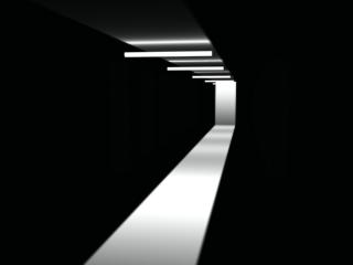
Angle=0
Illustration LO-15
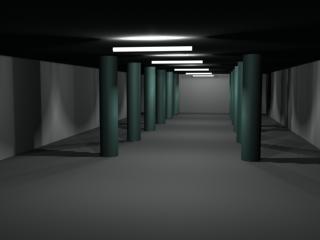
Angle=120
Radius
![]()
This defines the radius of the cylinder hot Increase this number if you want to
get a bigger area at which the light is emitted from. Keep in mind that this
also increases the surface area of the cylinder light and this pleys a big role
on the total energy distribution from the surface.
Height
![]()
Change this value to increase or decrease the height of the cylinder light.
Changing this parameter influences the total are a of the surface or where the
light is emitted. This plays a big role in the energy distribution.
Hotspot
![]()
Usually you want that the height of the cylinder light to reflect the hotspot
area of the cylinder light. For special purposes you may change the hot spot
area. However, the hotspot can't be greater than the height.
Illustration LO-16
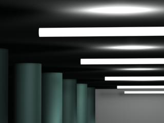
Hotspot=0,001
Illustration LO-17
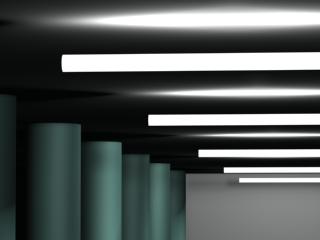
Hotspot=Heigth=22
Render Mesh
![]()
Check this radio button to rum on visible light emitters. With this option on
the cylinder lights be rendered as a self-illuminated cylindrical mesh.
Constant Energy
![]()
Check this option to get the same light intensities at every point on the
surface of the light source. If this option is turned off the lights energy is
averaged evenly around the cylinder shape. In such a case you might need to
increase the multiplier value to an incredible high amount (50 or even 100).
Affect Surfaces
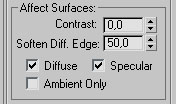
The settings are identical to those found in standard lights. Check the 3ds max
online manual for details of these parameters.
finalRender Shadow Types
Area shadows represent real world shadows much better than anything else on the
market. finalRender uses the latest technologies and new proprietary rendering
algorithms to render area shadows in 3ds max.
Illustration LO-18
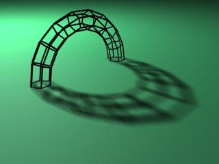
Illustration LO-18 shows an example of an area shadow. Note how the shadow gets
blurred with increasing distance to the shadow-casting object. One of the core
problems when rendering area shadows is the amount of rays that must be created
to get the correct blurring. Many extra rays have to be sent back in the shadow
render pass to detect the correct dimensions (area) of the light source.
To handle this task finalRender uses its own proprietary MSP-Tree algorithm to
know in advance how many rays are needed to get a certain render effect done.
This optimizing process is generally transparent to the user. However as the
scene gets more complex a dialog will pop up while rendering the scene to
inform you that the S building is in progress. finalRender also offers
advanced settings for the MSP-Tree, which can be found under Global.
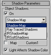
Ray traced area shadows can be assigned from within any standard light rollout
menu. To do this open the Shadow Parameters rollout and select from the drop
down list of shadow types fRSoftShadows. The rollout menu for the fRSoftShadows
looks like the one on the right.
The SoftShadow Rollout
Force 2 Sided
![]()
When this option is turned on all geometry will treated as two sided regardless
of the render status. Understand that this flag is only affecting the raytraced
area shadows and nothing else. The rendered geometry can still be single sided
but the shadows will not.
Illustration LO-19

Force 2 side = off
Illustration LO-20

Force 2 side = on
Use Transparency
![]()
As you might expect from a raytraced shadow, finalRender supports correct area
shadows cast by colored transparent objects. Check this option to activate this
feature, remembering however, that it will add more workload to the render.
Illustration LO-21
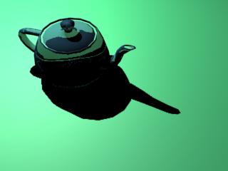
Use Transparency = off
Illustration LO-22
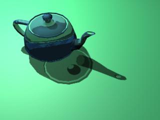
Use Transparency = on
Raytraced Shadows and Object Motion Blur
You must also check the Use Transparency option, to get correct motion blurred
raytraced shadows from fast moving objects. Such objects must use "Object
Motion Blur".
Soft Shadow Area Types
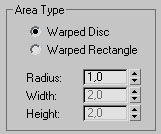
The whole idea behind soft shadows is that any real life light source usually
has an extension in 2D or 3D and isn't created, as Max standard lights are,
from a single point. Take a coated light bulb, the light isn't coming from a
single point in space but the light is emitting from the surface of the bulb.
Different shaped objects generate different shaped area lights and finalRender
offers two types of virtual area lights to choose from:
1.) Warped Disc
2.) Warped Rectangle
Warped Disc
This option is used to simulate a shadow cast by a disc shaped light source
(the Sun or a Flashlight). Radius sets the radius of the virtual disc that is
used to calculate the shadow finalRender uses a special proprietary disc
calculation method that warps the area a little bit in space. Warped areas create
much better area shadows than plain areas.
Warped Rectangle
This area shadow type can be used to simulate a shadow cast by a rectangular
light (neon tube or light box). Width and Height settings control the
dimensions of the rectangle. finalRender uses a special proprietary rectangle
calculation method that warps the area a little bit in space. Warped areas
create much better area shadows than plain areas.
Soft Shadow Surface Sampling
Raytracing is based on a physical computation model in which individual rays
are sent into a 3D scene and those are "followed around" until they
disappear or return a value. So everything is about shooting rays. As you can
imagine, rays are very valuable so it's a good idea to use them sparingly. As
we've explained, area shadows are created by shooting many rays back to the
"Virtual" light source, this method is completely different from the
one 3ds max uses to render raytraced shadows. Highly adaptive algorithms are
used to prevent sending unnecessary rays whenever possible. The three controls
used to fine-tune this adaptive algorithm are explained in the following
chapters.
Min Samples / Max. Samples / Accuracy
(SoftShadows)
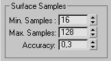
Each single ray traced shadow pixel may create an enormous amount of extra
rays. One shadow ray can explode into 128 or more individual rays. This happens
for each single shadow pixel. So be warned using high sample rates cause long
render times.
The method used by finalRender is adaptive and decides when to shoot more rays.
Two parameters let you control the ray creation process: Min. Samples and Max.
Samples. Min. Samples defines the amount of rays always shot from every shadow
pixel. Max Samples shoots as many rays as defined, whenever the algorithm
detects that more rays than Mim. Samples are needed. More shadow rays are
needed to get a smoother soft shadow. The adaptive algorithm of finalRender
needs some minimum rays to detect the "critical" regions in an image.
It would not make sense to have 2 Min. Samples and Max. Samples at 512 It would
be very unlikely that two rays are able to detect that more rays are needed to
get a smooth transition in the soft area of the shadow. We recommend using 416
Min. Samples at least. This depends also on the size of the virtual light
source, bigger area lights usually need more samples than.
Accuracy helps you to control the shadow ray creation. An accuracy of 1.0
(100%) will use all rays created by the algorithm to render the SoftShadows
effect. Less accuracy means that the amount of rays will be constantly reduced
by the factor defined by the Accuracy parameter.
Illustration LO-23 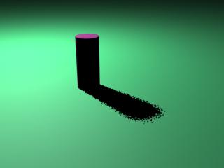
Min. Samples = 1, Max. Samples = 1
Illustration LO-24

Min. Samples = 16, Max. Samples
= 128
Volume Light Soft Shadows
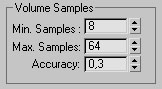
finalRender also supports rendering effects like raytraced soft atmospheric
shadow. As you have learned, area shadows are very computation intensive
effects. Now imagine the shadow calculation in 3D space (volume)! Atmospheric
are a shadows must create extra rays for every point in space (Min Samples, Max
Samples) to get the shadow intensity in a 3D volume. As you can imagine a
"big" volume light cone will create millions of extra rays that are
needed to render the shadows in the volume. Keep this in mind when you intend
to use this effect in a scene try to keep the volume as small as possible, this
will help in speeding up the rendering process. The parameters to control the
atmospheric soft shadow effect arc identical to those found in the surface
samples menu. Also the settings and behavior for rendering are the same. Note
that the volume samples section is used for the atmospheric shadow only. It is
a good idea to use different sample values for surface and atmospheric shadows.
Even though ifs not physically correct usually 30 won't notice the difference if the two shadow
sections use different amount of rays. The softness of both effects is
identical. However, as we explained volume effects are really processing
intensive and so ifs a good idea to use as less rays as possible. Another thing
that helps in saving rays in the volume is that the brightness of the volume
light effect is usually much higher in contrast to the shadow areas in the
volume. Errors introduced by reducing shadow rays in the volume do not affect
the visual appearance of the final rendering as much as it will with surface
shadows. You can learn more about the Min Samples, Max Samples and Accuracy
parameters in the previous chapter about the surface samples for raytraced so
ft shadows.
Blur (Soft Shadows)
![]()
Raytraced area shadows (soft shadows) are usually very time consuming rendering
effects. To get smooth results, a fairly high amount of rays must be shot into
the cebas1 invention "ULTRA BLUR(TM)" enables the user to render such
complex effects with a speed increase of up to 100 times! Check this button to
activate the ULTRA BLUR rendering of raytraced soft shadows. The blur amount
controls the smoothness of the shadow.
Tip
Keep in mind that this technology has some restrictions. One restriction is
that it's not possible to see ULTRA BLUR soft shadows in mirrors or through
refractive objects.
Ray Bias (Soft Shadows)
![]()
Increasing the bias moves the shadow away from the object and decreasing the
bias moves it closer to the object. The Ray-Trace Bias value an be any positive floating-point number. For example,
if a shadow-casting object intersects another object but its shadow doesn't
meet properly at the intersection, the bias is too high. This effect varies
with the angle of the spotlight to the object. Extremely shallow spotlight
angles usually require higher bias values. Another purpose of bias is to avoid
problems with objects that cast shadows onto themselves. If you see streaks or
moire patterns on the surface of the object, the bias value is too low.
Skip Co planar Faces (Soft Shadows)
![]()
Depending on geometry and the method of construction if s likely that you will
encounter some aliasing or false shadow pixels when rendering a scene with soft
shadows. The faces pointing slightly a way from the camera (towards the light)
can cause rendering problems. If you see streaks or moire patterns on the
surface of the object the Coplanar value is too low.
Threshold (Soft Shadows)
This parameter controls the falloff angle at which the shadows should not be
generated. A value of 1.0 means 90 degrees towards the camera or in other words
the face is perpendicular to the light source as seen from the camera point.
Tip
A threshold of 1.0 will remove all shadows from the objects! Lower values will
show more shadows on objects.
Globals/Global Exclude...
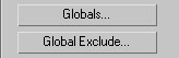
Click the Globals button to bring up the main finalRender Globals menu.
Raytraced shadows use the MSP-Tree acceleration function supplied by the core
rendering engine of finalRender. To speed up rendering of raytraced soft
shadows you may use the Global Exclude button to select any object that is not
involved in area shadow calculation. finalRender Stage-0 will also remove this
excluded object from any other raytracing based effect (reflections, global
illumination, reflections...). Keep this in mind when you prepare the scene for
optimization. The main finalRender Globals menu is explained in full detail in
the chapter finalRender Parameters.
Color Shadow Maps 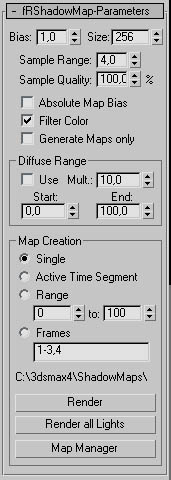
finalRender is the first light and shadow plug-in that overcomes a restriction
found in ads max, it does not respect transparent objects when you use shadow
maps. Raytraced shadows do respect transparency and color filtering, but they
are just too unrealistic be cause they are always way too sharp and accurate.
finalRender has none of those restrictions, it even offers one pass or two-pass
rendering with enhanced shadow map quality!
Bias
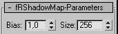
Map bias moves the shadow toward or away from the shadow-casting object (or
objects). By default, this value is 1.0 world coordinate unit. Increasing the
bias moves the shadow away from the object, and decreasing the bias moves the
shadow closer to the object. The Map Bias value an be any positive floating-point number. For
example, if a shadow-casting object intersects another object but its shadow
doesn't meet properly at the intersection, the bias is too high. This effect
varies with the angle of the spotlight to the object. Extremely shallow
spotlight angles usually require higher bias values. Another purpose of bias is
to avoid problems with objects that cast shadows onto themselves. If you see
streaks or more patterns on the surface of the object, the bias value is too
tow. If you increase the bias so much that the shadow becomes disconnected from
the object, reduce the bias and increase the shadow map Size value instead.
Size
Sets the size (in pixels) of the shadow map that's computed for the light. This
value will create a shadow bitmap with equal resolution in each axis! So be
careful when you increase this number! Bigger shadow maps create more accurate
shadows than smaller ones. With increasing map size the memory consumption and
processing time also increases. If the Size equals 512 then this means that the
shadow map will be 512x512 pixels!
Sample Range (Color Shadow Map)
![]()
Affects the softness of the edge of shadow-mapped shadows. The sample range
determines how much area within the shadow is averaged. Small values reduce the
area that is averaged, effectively bringing the edge of the shadow inward and
producing sharper edged shadows. Note that sharper edges can cause aliasing.
Large values extend the area that is averaged, effectively bringing the edge of
the shadow outward and producing softer edged shadows. Soft edged shadows have
more antialiasing. The effect is similar to the falloffof a soft-edged
spotlight. The default Sample Range value is 4. The Sample Range value can be
any floating-point number from 0 to 20. Values of 2 to 5 are recommended.
Values below 3 can produce coarse-edged shadows. You can reduce this effect by
increasing the map size. Values greater than 5 can produce streaking and moire
patterns. You can reduce this effect by increasing the map size or the Bias
value. Rendering time increases exponentially as the Sample Range value
increases.
Sample Quality (Color Shadow Map)
![]()
This controls the quality of the sampling area of the shadow map. Shadow Maps
are nothing more than special bitmaps. Softening of the shadow map edges is
done by filtering the edges of the relevant pixels. Filtering bitmaps is a time
consuming process and the time that is needed by the filtering function
increases by square with the size of the bitmap Reduce the Sample Quality to
get a faster but less accurate filtering of shadow map edges.
Absolute Map Bias
![]()
When on the bias for the shadow map is computed on an absolute basis, relative
to all of the other objects in the scene. When it's off, the bias is computed
relative to the rest of the scene. This feature is usually needed when you do
large scale scenes with small details in it, like "Will the fly cast a
shadow onto the planets surface.
Fitter Color
![]()
Check this option to get colored shadow maps in the volume shadow and also on
any other object in the scene. If Filter Colors is unchecked it behaves like
the standard MAX shadow maps except that it isn't possible to still see the
effects of transparency regardless of the filter color the object might have.
Generate Maps only
![]()
Check this option to turn off shadow casting onto other objects in the scene
but in the finalRender atmospheric effect This feature is really cool and
allows for fantastic special effects. Depending on the method of how the shadow
map was created you may create "ghosts" in a volume light. As soon as
the shadow maps are stored to jour hard disk the objects that caused the
shadows maybe deleted or hidden. The shadows will still be rendered as if the
objects were still in the scene.
Note:
If this option is turned off, the shadow will no more be visible on other
objects. The only way to still see the shadow is in a finalRender volume light
effect.
Diffuse Range (Color Shadow MAP)
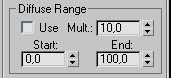
Use:
Check this option when you want to use the advanced area shadow code of
finalRender. When this option is turned on area shadows are created based on
shadow map technology. This is a really unique approach introduced to 3ds max
for the first time by finalRender! proprietary area shadow calculation method
is used to get the look for realistic area shadows but without the overhead of
area sampling and its potential artifacts.
|
illustration LU-25 |
|
illustration LU-26 |
As you can see in the illustration LU-25 and LU-26, image LU-25 shows standard
shadow maps without area shadow calculation code (Use = Off). Image LU-26 uses
the area shadow map calculation and creates a much more realistic shadow. This
calculation is also based on the distance to the shadow casting object,
however, it isn't based on the size of the light source as you can simulate it
with raytraced soft shadows.
Multiplier (Color Shadow Map)
This multiplies the sample range value based on the distance and light
visibility to the shadow casting object. Be careful, as larger values will make
the render time explode exponentially.
Example:
Let's say that you have a Sample Range f 4 and Mult. is set to 10. Whenever a shadow pixel
reaches the End range, the sampling area (smoothing) would be 10 x 4 = 40
pixels And as you can see from the big sampling area this will take some time
to process. The good news is that it's only done in the far range area so not
all pixels are.
Start (Color Shadow Map)
Sets the start range of the area shadow map calculation. This value is measured
in world units and sets the absolute distance to the shadow casting object.
|
illustration LU-27 |
|
illustration LU-28 |
Illustration LU-27 shows the area shadow effect beginning right from the start
of the object. In illustration LU-28 you can see that the blurring of the
shadow starts at a distance of 50 units from the object casting the shadow This
is how you can control the shadow to stay sharp and then to blur really fast.
End (Color Shadow Map)
Sets the end range of the area shadow map calculation. It means the distance at
which the most Hurting should occur Between Start and End the blurring of the
shadow increases smoothly.
Shadow Map Handling 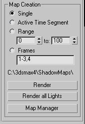
All shadow maps created with finalRender can be pre-rendered for later access
when rendering on a single PC or network. Storing shadow maps on hard drive
offers many advantages. One advantage is the option to some image processing in
a later stage of the production process. You may color correct color shadow
maps, add additional Hurting or any kind of other image based effects to the
maps stored on your hard drive. This option needs some kind of planning as it
may turn out that you end up with hundreds or thousands of different maps created
by one 3ds max scene. Another great advantage in storing shadow map files onto
the hard drive is once they are rendered you do not need to render them again
except when the shadow casting objects change in the scene. finalRender shadow
map files are stored as standard 3ds max RPF files. Those files can be easily
edited by combustion, for example.
Single (Color Shadow Map)
![]()
Check this option to render the shadow for the selected light at the current
frame
Active Time Segment (Color Shadow Map)
![]()
When this option is checked, all frames in the animation range are rendered to
ere ate the color shadow map files.
Range (Color Shadow Map)
![]()
Check this option to tender a range of an animation Use the two entry fields to
set the range (number of frames) of the animation.
Frames (Color Shadow Map)
![]()
For more control you may choose specific frames or even separate ranges.
Path Display (Color Shadow Map)
![]()
Beneath the frames text field you'll find the shadow map path settings. Make
sure that this line shows the correct path information for the local machine.
This path entry maybe incorrect if you got this scene from another machine that
used different drive settings.
Render (Color Shadow Map)
![]()
Press this button to render the shadow map as viewed from the selected light
source. This button renders only the selected light object. It doesn't matter
which ads max viewport is active while you render shadow maps.
Render All Lights (Color Shadow Maps)
![]()
Activate this option to render all shadow maps from 211 lights that use a
finalRender shadow map. This is a useful feature as it allows you to render all
shadow maps without selecting each light in the scene.
Map Manager (Color Shadow Map)
![]()
Click this button to open the Shadow Map\Tanager dialog.
Shadow Map Manager Dialog 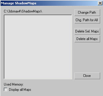
Change Path (Color Shadow Map)
This option allows you to set the path where the color shadow map files are
stored. Remember to choose a path that can be accessed by all PC's if you
intend to do net work rendering.
Change Path for All (Color Shadow Map)
Everv light in the scene map store its own color shadow maps in a different
folder. You should avoid spreading shadow map files all over your hard drive as
it becomes very hard to keep track of them. Use this path option to change the
paths for all lights in the scene in one go.
Delete Sal Maps (Color Shadow Map)
Click this button to delete the selected shadow map.
Note, finalRender is not able to decide if a shadow map is outdated (something
changed in the scene) and if it needs to be updated. Only when a shadow map is
deleted and it does not exist in the path supplied is a new one created
automatically. The exact behavior depends on the Automatic Save/Creation flag
of the color shadow map. As explained in the previous chapter you may create
the shadow maps in three ways:
1.) Fully automatic like 3ds max standard shadows
2.) Manually, stored to a specific folder
3.) Fully automatic, but stored to a specified folder
Delete all Maps (Color Shadow Map)
Click this button to remove all rendered shadow maps from this list and your
hard drive. Be careful, as there is no undo for this operation!
Close (Color Shadow Map)
Click this button to close the dialog.
Used Memory (Color Shadow Map)
For your convenience the total memory consumption is displayed here.
Display all Maps
When this option is checked all shadow map files created by every light in the
scene are listed. y default the shadow map files of the selected light
are listed.
What is a Caustic?
finalRender supports two types of caustic effects, one by retracting light
exams the other by reflected light beams. This effect is a natural phenomenon
produced by one or many focal points of multiple light raps. Mother nature
doesn't differentiate between caustics created by reflection or refraction, the
cause is always the same. Light raps hitting onto a reflective surface bounce
off in a specific way and assemble in a focal point somewhere near to the
object Transparent objects will bend the light rays and some of them will fall
into one focal point creating a caustic light effect on other surfaces.
|
illustration LU-29 |
|
illustration LU-30 |
Illustration LU-29 presents a glass lens creating caustics. Many light rays hit
the same point on the surface. The white lines represent some of the light rays
traveling through the glass lens. Illustration LU-30 shows a reflective chrome
ring creating caustic light effects on surface. The white lines represent rays
of fight hitting the chrome surface and bouncing off the surface in a specific
angle. Caustic patterns arc visible only when there is a focal point (or area)
where many light rays fall together. Isolated caustic rays won`t have any
visible influence. Objects with curved surfaces (non-planar) will always
generate one or more focal points where all the rays fall together to create a
caustic light effect. You can find some samples and a visualization of the
effects in illustration LU-29 and LU-30. The big white lines represent the
light rays with their paths from the light source. As you can imagine real flat
surfaces or planar objects won't create nice caustic effects as these surfaces
tend to scatter the light in all directions with no chance to create a focal
points where more rays fall together.
Volume Caustics
Illustration LU-31
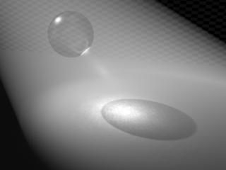
Volume caustics follow the same rules like standard caustic effects. However,
they are volumetric and so the effect happens not just on a surface but also in
a 3D volume! Bent and focused light rays become visible in a volume effect like
a volume light effect does. This is the ultimate rendering technology of today.
Illustration LU-31 is a good example of a volume caustic effect. The glass
sphere bends and focuses the light rays to a specific point. The rays arc
visible because of the simulated volumetric light effect. You need to
understand that this is a true 3D effect. The complete volume must be sampled
and covered to get the correct volume light effect rendered.
So how does it work?
finalRender uses a special 3D database called Photon-Tree to store photon
energy data. Photons can be described as light particles that travel through 3D
space and their initial energy is constantly reduced as they hit or collide
with objects in the 3D scene. If s easy to imagine that this process needs a
lot of processing power especially when you want to simulate physically correct
the energy distribution in a 3D scene.
One fight ray may create hundreds or even thousands of Photons along its path
Such Photons influence the final look of the caustic effect a lot as the can change color or lose energy along the way Surface
caustics are not so expensive to process compared to their volumetric
counterparts. Photon tracing (the caustic creation process) happens before
rendering - the photon database must be filled with energy and color values
before the actual rendering starts.
Setup of a Caustic Effect.
You must do some preparation in advance when you want to create a finalRender
effect that involves caustics, either refractive, reflective or volume
caustics. Here is the list of things to do:
1) You need to adjust the photon shooting light at fast
2.) Next you must assign a finalRender material to the objects of your choice.
Also you should change the objects properties.
3.) Finally you must setup the caustic material and the Global settings
As you can see from the list above almost all areas of 3ds max must be touched
before you can start rendering caustic effects. Y u need to setup the light sources from the lights
rollout panel and then you need to setup the materials so that the objects in
the scene are able to receive and create caustic effects. Finally tweaking the
Global settings to achieve the look you want.
Important
finalRender supports standard 3ds max materials in receiving and generating
caustic effects. Restrictions in the 3ds max programming interface forced us to
implement the support of standard materials in a very special way.
The following description is valid for all standard 3ds max materials, however,
we recommend using the finalRender material to create caustic effects. It
offers much more powerful features and it's much faster compared to the built
in materials.
How do I make a standard 3ds max material
receive or generate caustic effects?
Each object in 3ds max offers standard object properties that an be accessed by a single right mouse lick on the object. The object properties dialog
presents lots of parameters an object might have. There are flags like receive
shadows or generate shadows, visible to camera and so on. With finalRender
installed you will get additional options activated in the object properties
dialog of 3ds max. finalRender utilites the mental ray properties section of the
object properties dialog. Usually these settings are inactive and can't be
accessed by the user until mental ray or finalRender is installed. The
additional object properties available are Generate Caustics, Receive Caustics,
Generate Global Illumination and Receive Global Illumination.
Every object in the 3D scene must have the additional caustic flags set
properly Only when this is done will each object render caustic effects. This
will happen regardless if it's a finalRender material or any standard 3ds max
material. A finalRender material must be added to the scene to render caustic
effects with only standard materials. This is done easily by adding a
finalRender material to a free slot in the material editor. Note that there is
no need to assign it to any object in the scene. The presence of a finalRender
material in the material editor is enough to activate the finalRender
raytracing engine for the scene. Standard 3ds max materials do not offer any
caustic parameters or additional settings, those global settings must be set in
the Globals menu of the finalRender material. These global settings are valid
for all 3ds max materials and for finalRender materials. In contrast to
standard materials you may change the caustic settings locally for each individual
finalRender material. Ifs one reason why we suggest using finalRender materials
instead of standard 3ds max materials. Rather than start new each time
finalRender offers several ways of converting standard materials to finalRender
materials and back.
Let's start doing Caustics
In this chapter we introduce you to the workflow of creating caustics with
finalRender. Please take your time and read this chapter about the
implementation of caustic effects in finalRender. You'll find the caustic tools
and settings of finalRender in multiple sections of 3ds max.
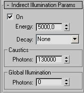
Every new and old light source in a scene has an additional rollout menu added
to it called "Indirect Illumination Params". This light rollout
dialog offers all parameters to control the amount of Photons and initial
energy levels. You may also set a certain amount of physically correct energy
decay as the Photons travel through the scene.
Keep in mind that this light rollout menu utilites the mental ray menu which is
a separate rendering product from DISCREET. We used this to avoid adding more
rollout menus to all of the light sources in a scene. finalRender does not use
the Global Illumination section of this rollout menu in contrast to mental ray
Photons are not used to render indirect illumination in finalRender.
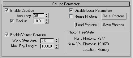
Once you have set up all lights in a scene, materials and object properties are
neat. We recommend using a finalRender material on all objects receiving or
gene rating caustic effects. By assigning a finalRender material to each of the
objects you can decide how accurate the caustic effect should be on a per
material basis.
Another way to control the caustic effect in finalRender is by adjusting the
object properties for each single object. The object's properties menu can be
accessed for one or many objects by a single tight mouse click.
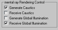
The illustration above shows the lower left part of a standard object
properties menu. All four heck boxes work with finalRender!
Tip
Object properties will always overwrite material settings!
If for example an object has Receive Caustics turned off but it uses a
finalRender material with Receive Caustics turned on, no caustics will be
rendered on this object. Using the object properties menu is a great way of
excluding single objects from the specified rendering effects. While other
objects with the same finalRender material may still receive caustics single
objects with that property turned off won't see this effect. This is the main
reason why we strongly recommend using the finalRender material instead of
standard 3ds max material.
Last but not least, you need to create some transparent or reflective objects
to create some caustic beams in the scene. Nice caustic effects demand a
material or object with refractive or reflective properties.
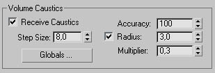
Besides the steps described above there is one more place left in 3ds max you
need to adjust. If you wish to create a volume caustic effect (as shown in
Illustration LU-31) you need to activate the relevant settings in the
finalRender volume light rollout menu. You will find a detailed description of
the finalRender volume light effect in the next chapter.
Summary
The setup of a caustic effect involves several steps to be performed. Also,
many different parts of the ads max interface must be accessed to achieve this
goal. Here is a summary of the general workflow.
1.) Modify the light object that you want to act as a "photon
shooter" (Modify Light)
2.) Check/Adjust the object properties accordingly (single right mouse click)
3.) Assign a finalRender material to the scene or material editor (Modify
Material)
4.) If needed, adjust in "Render Effect" or "Render
Atmosphere" the volume light
5.) Make sure that there is at least one object creating and receiving caustics
in the scene
Caustic Material Settings 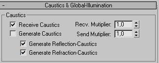
A finalRender material is the preferred material type when you want to render
any special finalRender effects like caustics or Global Illumination. In
contrast to standard ads max materials you will get extra in depth control of
the caustic effect when you use the Local Parameter rollout menu to adjust the
toe al settings f an effect. The local parameter menu of a finalRender
material lets you decide on a per material bases if an object or surface should
create or receive a caustic effect. The great thing about this is that each
material can have different settings and this might help you in speeding up the
rendering. Find below the parameters of the local settings.
Remember to read the chapter about the finalRender Global Settings menu.
Receive Caustics (Local Parameters)
![]()
Check this option to make the material receive caustic effects created by
Photons bouncing off 2 reflective material or by refracted light rays.
Generate Caustics (Local Parameters)
![]()
Check this option to make the material a caustic generator. This only makes
sense for refractive or reflective objects.
Accuracy (Local Parameters)
![]()
Sets the amount of Photons to be se arched for by the finalRender caustic
engine. Higher numbers me an that more Photons are collected before the final
light energy for a point on the surface is calculated.
Tip
Larger, numbers tend to wash out the caustic effect.
Radius (Local Parameters)
![]()
This value is used whenever the radio button is checked. It defines the radial
are a in world units for the caustic engine to look for Photons in space.
Larger numbers will ere ate better more realistic images. As you can imagine se
arching in a bigger area and averaging such an are a will take more time to
render! For fast rendering keep this value as low as possible.
Tip
You an
tell that the radius value is too low, as you will you starting to see single
spots or splashes of lights where they shouldn't be. get rid of this increase the radius value.
Indirect Illumination Params
As described in the chapter "Let's start doing Caustics" finalRender
adds a new rollout menu to the light panel of each single light object in the
scene. It lets you define the amount of Photons (light particles) each light
source should shoot out into the scene.
Tip
finalRender uses the 3ds max mental ray interface by activating it when
finalRender is installed!
The Global Illumination menu section isn't
used in finalRender! It's not needed, as finalRender does not use photon maps
to render Global Illumination effects.
Find below a description of the Indirect Illumination parameters.
On (Indirect Illumination Params)
Check this option to turn the light into a photon emitter. This is great for debugging
purposes as it lets you temporarily switch off the effect.
Energy (Indirect Illumination Params)
This parameter sets the amount of initial energy for all Photons. The energy
value is divided amongst all Photons (Energy/ number of Photons) shot into the
scene. Depending on the distribution of the Photons it might be necessary to
increase the energy level a lot (greater than 10.000).
Decay (Indirect Illumination Params)
This parameter is used to simulate a natural effect of Photons. In the real world
light loses energy by square as it travels a way from its source. For jour
convenience you may choose between three falloff methods: None, Inverse and
Inverse Square.
Photons (Indirect Illumination Pararns)
Sets the number of Photons that should be shot into the scene from the selected
light source. Higher numbers will create a more realistic look of the caustic
effect. Be warned though, if you overdo the amount of Photons in a scene you
might end up waiting forever for the image to render.
Volume Caustic Interface
finalRender uses the latest state of the art technologies to render volume
caustic effects to create interesting and photo real images. A good knowledge
of how the effect is created is needed to speed up the creation process.
Remember
Keep in mind that you need to prepare several things before you may be able to
see a volume caustic effect. The lights need to be adjusted and then the
object's properties or material needs some adjustments to render the caustic
effects. Also a fRVolumeLight entry must be added under "Render
Effects" or "Render Atmosphere". Only the lights with a
finalRender Effects & Atmosphere added to them will be able to create volume
caustic effects. The following list of volume caustic parameters is also
explained in the chapter finalRender Volume Light Effects.
Receive Caustics (Volume Caustic)
heck this
option to make the volume receive caustic effects. Volume caustics will be
rendered only for those lights with this flag turned on.
Step Size (Volume Caustic)
Sets the amount of volume steps through the 3D volume. Be careful though as
lower values result in long renders. We suggest to use values between 3 and 15.
Tip
You can tell that the Step Size value is too high when you start seeing an
offset between the volume caustic ray and the surface caustic effect. In this
case reduce the step size.
Globals (Volume Caustic)
Press this button to open the main finalRender Globals dialog.
Accuracy (Volume Caustic)
Sets the amount of Photons to be searched by the finalRender caustic engine.
Higher numbers mean that more Photons are collected be fore the final light
energy for a point in space is calculated.
Note:
Larger numbers will tend to wash out the caustic effect
Radius (Volume Caustic)
Radius is used whenever the radio button is checked. It defines a spherical
volume in world units for the caustic engine to look for Photons in space.
Larger numbers will create better, more realistic images. As you can imagine
this will also take more time to render! Keep this value as low as possible
especially for volume caustics!
Tip
You can tell that the radius value is too low when you start to see single
spots or splashes of lights where they shouldn't be. To get rid of these
increase the radius.
Multiplier (Volume Caustic)
To enhance the effect of volume caustics (make them brighter) increase this
value.
Volume Light Effects
finalRender is a raytracing system that offers all kinds of illumination
options within 3ds max, one of the most advanced parts in finalRender is the
volume light effect. No other plug-in for 3ds max offers such depth of control
to create volume light effects. Volume fight effects are used to simulate
visible light beams that are caused by dust or other tiny particles in the air.
In the real world light beams are only visible because of particulate matter
like fog or dust In contrast to the built in 3ds max volume light effects,
finalRender has to offer an incredible amount of flexibility and rendering
speed. In fact, it's the only volume light plug-in that works in near real time
when updating even the most complex volume light effects.
|
The Volume Light Interface |
|
How to access fRVolumeLight 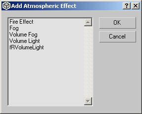
Every light source or finalRender object light has an Atmosphere & Effects
rollout menu in modify mode. This menu allows you to add or re move a volume
light effect or any other render effect. As you can see in the illustration
above, there are two finalRender volume light effects available. One being the
"real-time" Render Effect and the other being the real 3D volumetric
render effect. The Add Atmosphere Effect user dialog displayed by ads max has
also some options. Those are described in the 3ds max user manual, however are
want to stress that you may use the Atmosphere or Effect radio button to know
which effects are 2D post effects and which ones are real 3D effects. After
selecting the effect of your choice, you may proceed as usual with the Setup
command button of the light rollout menu.
In the tutorials section of this manual we will describe in detail how to add a
volume light effect to a scene.
Volume Light Parameters
You'll find the basic volume light parameters in the main rollout dialog of
finalRender atmospheric or render effect interface. This dialog is only
accessible when the relevant atmospheric entry is selected in the atmospheric
menu of 3ds max.
Many parameters you find there are identical to those found in 3ds max.
However, keep in mind that the finalRender atmospheric is much more
sophisticate d and use s all the "internal" methods and functions
finalRender has to offer. For example, the advanced color shadow map is only
accessible by the finalRender atmospheric plug-in.
Pick Light (Volume Light)
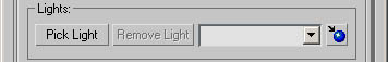
Activate the Pick Light button and then click onto any light in the scene that
you want to enable as a finalRender volume light effect.
Note:
You can pick multiple lights. Click Pick Light and then press the H key. This
displays a Pick Object dialog that lets you choose multiple lights from the
list.
Remove Light (Volume Light)
Select any of the lights in the drop down list and then click the Remove light
button to delete a light from the list.
Parameter Transfer (Volume Light)
![]()
Click the Parameter Transfer icon to bring up the Get Parameters dialog. This
feature is very useful when there is more than one volume effect in the scene.
From the list you may choose any Atmospheric or Render Effect to get (or
convert) the settings from one to another. Please note that this parameter
transfer is only possible between finalRender volume light effects and standard
Volume Light effects. Any other atmospheric or render effect can't be transferred
to a finalRender volume light.
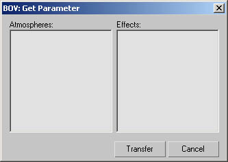
Tip
it's always a good idea to do some house keeping before starting or changing
any scene. Remember to name each individual effect, as you can imagine later on
it's not easy to find the right effect entry when all effects are called
fRVolumeLight.
Fog Color (Volume)
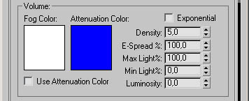
Sets the color for the fog that makes up the volume of the light. To change it,
click the color swatch and then choose the color you want in the Color selector
dialog. You an animate the color effect by changing the fog lor at a nonzero frame with the Animate button on.
This color swatch also controls the "start" color in the Color
Parameter Rollout menu. Bear this in mind when you activate the Use Attenuation
Color, when activated, the color swatch is automatically linked to the first
key in the color graph.
Tip
This fog color mixes with the color of the light. For the best effect use white
fog and then color it with a colored light.
Attenuation Color (Volume Light)
This attenuates volume light over distance. The volume Light ramps from the Fog
Color to the Attenuation color over the lights Near and Far attenuation
distances. Clicking swatch displays color selector to change the attenuation color.
Remember that effect is only visible when you activate the Use Attenuation
Color radio button. When you do this, the color swatch win be linked to the
last color key in the Color Parameter rollout menu Any changes to this color
swatch will be reflected as three (R,G,B) curves or lines in the color graph
rollout dialog.
Tip
Attenuation Color interacts with Fog Color. For example, if our fog color is red and your attenuation color is
green in the rendering our fog will shade to purple. Usually the attenuation
color should be very dark and neutral, Hack being a good.
Use Attenuation Color (Volume Light)
Check this option when you want to activate the attenuation color effect. This
option also activates the advanced color gradient feature of finalRender
volume.
Exponential (Volume Light)
Check this button to increase the fog (or dust particles) density exponentially
with distance. When turned off density increases linearly with distance. This
feature should be used when you want to render transparent objects in volume
lights.
Density (Volume Light)
Sets the density of the fog. The denser the fog the more the light reflects off
it inside the volume. We suggest that you use densities between 2 and 15
depending on the other settings you might have chosen.
Note:
Even with high density values you may get very transparent effects. This value
is multiplied by the value found in the alpha value (density) of the color
graph found in the Color Parameter rollout menu. A density of 100 an drop down to zero when the alpha key in the color
graph is set to zero (100 x 0 = 0).
E-Spread (Volume Light)
![]()
Energy Spreading is an advanced finalRender feature for volume fights and it
causes the volume effect to look more realistic or not be careful, it's the
final look of the image that might create a realistic impression that the
calculation isn't real for this Energy Spreading effect.
Here is an easy rule of thumb on how you would use the E-Spread parameter. A
value of 0 will create nice "realistic" looking images and a value of
100 will create images that while calculated physically correct tend to look
not as real to the viewers eye.
In the illustration BO-01 and BO-02 you'll notice the dramatic change when you
play with the E-Spread setting. Illustration BO-02 uses an E-Spread of 0%, as
you can see the volume's density isn't used to calculate the overall fog
illumination and density! It's the light source alone that controls the volume
effect. In illustration BO-01 you can see the opposite (E-Spread=100), the
effect now respects 100% the volume. The light (or illumination) energy is
spread evenly within the whole volume. Compact or smaller volumes (the light
cone) would appear brighter in contrast to the standard 3ds max behavior, which
is the exact opposite.
|
illustration BO-01 |
|
illustration BO-02 |
Max Light% (Volume Light)
Represents the maximum illumination of the volume effect that you an achieve. Lower numbers will result in a lower
brightness of the volume effect.
Min Light% (Volume Light)
Min Light% centrals the fog effect (volume) overall and outside the volume cone
(or ray/sphere).
Values that are greater than 0 will create a haze or general fog outside the
light's restricting volume. Understand this means that areas of open space
(where the light ray can travel forever) will end up the same as the fog color
(just as with normal fog). It usually makes sense to use this feature only when
the camera "sits" inside an environment. Make sure you have geometry
around the camera view, a background only will end up with an unwanted flat
colored effect.
Luminosity (Volume Light)
Sets dig amount of "additive pixel blending" for the volume light
effect. This value can be seen as an intensity factor for the volumetric
effect. It lets you control how much the background "in" the volume
effect is brightened by the volume itself. Higher values will brighten up the
background in the volumetric effect.
Check out the illustrations shown be low, a Luminosity value of z will not affect the background pixels in the volume.
Illustration BO-04 uses a luminosity value of 100 and this causes all objects
behind or in the volume effect to get brighter. In areas without any geometry
behind or in the volume light effect, the pixels will not be affected and they
keep their original intensity You may also use Luminosity numbers as high as
500 (or even more) but it might create bad aliasing problems and false colors
may.
|
illustration BO-03 |
|
illustration BO-04 |
|
illustration BO-05 |
Atmospheric Shadows
finalRender uses enhanced shadow calculation methods for volume light shadows.
Compared to ads max, finalRender uses shadow information in a completely-
different way. For example, finalRender is able to use raytraced shadows to
cast a shadow in the volume light effect, 3ds max is not able to do this. Also
with raytraced shadows it means that you can also use raytraced soft shadows to
render the shadow effect in a volume light. If you plan to use such advanced
rendering features make sure that you understand the concepts of creating such
ray tracing effects like soft shadows or volume light shadows. Everything has
to do with casting rays and more rays always means more time to render! A soft
shadow effect, for example, creates per shadow pixel up to 128 rays or even
more. Now soft shadows in a volume will create the same amount of rays per
pixel but because we are talking about a volume this means. The amount of rays
explodes by a cubic (^3) amount. Do you better be prepared for some long render
times when you start to use these advanced features.
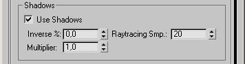
Use Shadows (Volume Light)
Check this option if you want to see shadows cast in volume light effects. This
includes shadow maps, raytraced shadows, finalRender raytraced area shadows and
finalRender color shadow maps.
Tip
Raytraced shadows are only visible in the final rendered image and not in the
Render Effect preview!
Inverse% (Volume Light)
When set to 0, finalRender will render volume light effects as you would expect
from standard 3ds max. Values higher than 0 will turn the volume effect into
its inverse counterpart. Inverse means that shadows will be bright and former
bright areas will be dark.
|
illustration BO-06 |
|
illustration BO-07 |
|
illustration BO-08 |
Multiplier (Volume Light)
This parameter lets you control how "dark" the shadow in the volume
should be. A value of 1.0 will use the exact shadow "darkness" as
calculated by finalRender. All other values will increase or decrease shadow
brightness in the volume.
Raytracing Smp. (Volume Light)
This only affects r ytraced shadows in volume light effects. The amount of
volume samples will affect the final raytraced shadow quality and the render
time needed to finish the image calculation.
Tip
Do not use numbers higher than 50 unless you really need it. Due to several
restrictions in 3ds max it might be very common that you'll get a certain
amount of pixelation in the darker areas of the shadow casting object.
Volume Light Attenuation
finalRender supports all standard 3ds max light and illumination features but
it does also offer much morel In fact finalRender offers one of the most
advanced volume effects available for 3d studio max. One example such an
advanced function is the use of the advanced attenuation feature called light
mattering.
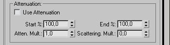
Use Attenuation (Volume Light)
Check this button to activate the light attenuation effects to be used by the
volume light calculation. The controls in this section are reliant upon the
settings of the Start Range and End Range attenuation parameters for each
individual light Rendering volume fight at some angles can introduce aliasing
problems. To eliminate aliasing problems activate the Near and Far Attenuation
settings in the light object that the volume light applied to.
Tip
Regardless if you check this option or not, note that many finalRender features
will always use the Far Range End to normalize falloff curves or other advanced
volume effects! Bear this in mind when you adjust other finalRender effects.
Start% (Volume Light)
Sets the start attenuation of the light effect relative to the actual light
parameter's attenuation. It defaults to 100 percent, which means that it starts
attenuating at the Start Range point of the selected light When you reduce this
parameter, it starts attenuating the light at a reduced percentage of the
actual Start Range value of the light itself.
End% (Volume Light)
Sets the end attenuation of the lighting effect, relative to the actual light
parameter's attenuation. By setting this lower than 100 percent, you can have a
volume effect stop way before the actual illumination of the light stops! This
is great for mysterious scenes with re ally dense fog effects when-, the fog
eats up a lights energy re ally fast.
Attenuation Multiplier (Volume Light)
finalRender uses the attenuation multiplier in a different way to how 3ds max
uses it. This parameter will boost the attenuation effect of the volume. Higher
numbers will make the volume diminish much faster, rather than changing any
other settings in the light object.
Scattering Mult. (Volume Light)
Any nonzero value will activate the 'Volume physics mode' causing finalRender
to behave like you would expect it to in Mother Nature. This means that with increasing
distance the light intensity falls off b square, or whatever amount you have chosen for each
individual fight!
Increasing numbers will boost the distance dependency of the volume light
effect The idea behind this is to simulate the natural behavior of light losing
energy. The volume effect (visible light) usually simulates dust or fog, these
are just particles that reflect the light back into the cameral Only
finalRender is able to render such a physically correct volume light effect,
standard features in3ds max wouldn't be able to simulate this effect. How is it
done? finalRender measures the distance from the camera to each single
"Virtual" particle and takes this into account when rendering volume
light effects.
Real world example:
Imagine you are walking at night through a very dense foggy landscape. The
flashlight in your hand will create a nice light beam in the fog. While you are
still able to see the light beam, a person standing 100 feet away wouldn't be
able to see you or the light be am in the fog. With standard ads max volume
lights you would still see the light beam regardless of the distance of the
observer.
Volume Caustics 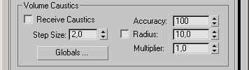
Volume caustic effects are really great to help create interesting and photo
real images. finalRender uses the latest technologies to render such effects in
the least amount of time. However, a good understanding of how the effect is
created helps a lot in preparing the rendering engine to speed up the creation
process.
Remember!
Keep in mind that you need to prepare several things before you maybe able to
see a volume caustic effect. The light(s) needs to be adjusted, the object's
properties and also material need some adjustments to render caustic effects.
Also a fRVolumeLight entry must be added under "Render Effects" or
"Render Atmosphere". Only the lights with a finalRender Effects &
Atmosphere added to them will be able to create volume caustic effects.
Receive Caustics (Volume Caustic)
Check this option to make the volume receive caustic effects. Volume caustics
will be rendered only for those lights with this flag turned on.
Step Size (Volume Caustic)
Sets the amount of volume steps through the 3D volume. Be careful Lower values
will result in long render times. We suggest you use values between 3 and 15.
Tip
You an tell that the Step Size value is too high when you start seeing an
offset between the volume caustic rap and the surface caustic effect, in this
case reduce the Step Size.
Globals (Volume Caustic)
Press this button to get the main finalRender Globals dialog.
Accuracy (Volume Caustic)
Sets the amount of Photons to be searched for by the finalRender caustic
engine. Higher numbers mean that more Photons are collected before the final
light energy for a point in space is calculated.
Note:
Larger numbers tend to wash out the caustic effect.
Radius (Volume Caustic)
Radius is used whenever the radio button is checked. It defines a spherical
volume in world units for the caustic engine to look for Photons in space.
Larger numbers will create better, more realistic images. As you can imagine
they will also take more time to renders Keep this value as low as possible
especially for volume caustics!
Tip
You an tell that the radius value is too to w when you start to see single
spots or splashes of lights where they shouldn't be. To get rid of this
increase the radius value.
Multiplier (Volume Caustic)
To enhance the effect of volume caustics (make them brighter), increase this
value.
Volume Light Color Parameter 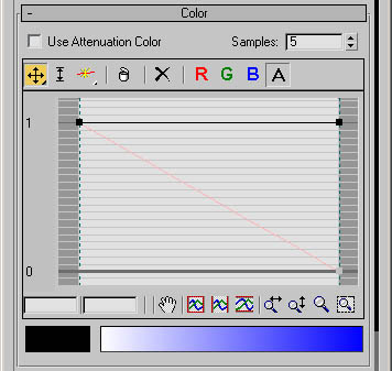
The Color Parameter Energy Graph is one of the most powerful features of
finalRender. It lets you create everything you want, giving you total control
over the volume light effect. This rollout menu is divided into several
sections that you might already know from standard 3ds max tools. In fact this
dialog is identical in use to the one that can be found in the 3ds max material
editors Output rollout menu. We recommend that you check out the MAX online
manual if you are in any doubt as how to use this tool. This curve control is
100% animatable, just with standard 3ds max features every aspect may be
animated.
There are some basic rules you must understand be fore you start working with
the Energy Clor Graph. The left side of the Energy Color Graph (point 1,0)
always represents the position of the light source (light emitter)! The right
side of the Energy Color Graph re presents the End Far Range of the light
source, regardless if used or not.
Use Attenuation Color (Volume Light)
Check this button to make finalRender use the color definitions found in this
Energy Color Graph or leave it unchecked to use the two colors found in the
main rollout (Fog Color and Attenuation Color).
Samples (Volume Light)
This parameter controls the curve sampling in relation to the intersecting
points in the volume. In other words: more samples means better quality and
representation of the drawn curve! We recommend you not use more than 20
samples, higher values will result in much longer rendering times!
The following onto is affect the points on the graph:
Color Channel Selector
![]() - Enables the Red color curve
- Enables the Red color curve
![]() - Enables the Green color curve
- Enables the Green color curve
![]() - Enables the Blue color curve
- Enables the Blue color curve
![]() - Selects the Density curve
- Selects the Density curve
Move
![]() - Moves a selected point in any direction, but not
across each other
- Moves a selected point in any direction, but not
across each other
![]() - Constrains movement to the horizontal
- Constrains movement to the horizontal
![]() - Constrains movement to the vertical
- Constrains movement to the vertical
You may turn any point into a Bezier point by right-clicking and choosing
Bezier Corner or Smooth. On a Bezier smooth point you can move the point or
either handle to adjust the curve.
![]() - Scale Point
- Scale Point
Changes the output amount of control points while maintaining their relative
position. On a Bezier comer point this control is effectively the same as a
vertical move. On a Bezier smooth point you can scale the point itself or
either handle.
Add Point fly out
![]() - Adds a Bezier corner point anywhere on the graph
line.
- Adds a Bezier corner point anywhere on the graph
line.
![]() - Adds a Bezier smooth point anywhere on the graph
line.
- Adds a Bezier smooth point anywhere on the graph
line.
When either Add Point button is active, you can use CTRL+ click to create the
other type of point. This eliminates the need to switch between buttons.
Delete Point:
![]() - Removes selected
- Removes selected
Reset Curves:
![]() - Returns graph to its default, a straight line
between 0,0 and
- Returns graph to its default, a straight line
between 0,0 and
The following controls affect the view of the graph. The change in vicar does
not affect the graph`s results.
Pan:
![]() - Drags the graph in any direction within the viewing
"window.
- Drags the graph in any direction within the viewing
"window.
Zoom Extents:
![]() - Shows the entire
- Shows the entire
Zoom Horizontal
![]() - Shows the entire horizontal range of the graph.
- Shows the entire horizontal range of the graph.
Zoom Vertical
![]() - Shows the entire vertical range of the graph
- Shows the entire vertical range of the graph
Zoom Horizontally
![]() - Compresses or expands the graph in a horizontal
direction
- Compresses or expands the graph in a horizontal
direction
Zoom Vertically
![]() - Compresses or expands the view of the graph in a
vertical direction.
- Compresses or expands the view of the graph in a
vertical direction.
Zoo
![]() - Zoo this in or out around the cursor.
- Zoo this in or out around the cursor.
Zoom Region
![]() - Draws a region around any area of the graph, then
zooms to that view.
- Draws a region around any area of the graph, then
zooms to that view.
Color Swatch
![]() - Represents the actual color value at the position of
any selected point.
- Represents the actual color value at the position of
any selected point.
Color Gradient
![]() - This gradient represents the color blending over
distance (from light source to Far End)
- This gradient represents the color blending over
distance (from light source to Far End)
Volume Light Fall Off 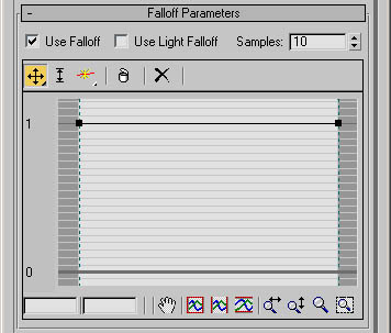
The second big feature in finalRender volume light effects is the Falloff
Energy Graph. This is a powerful feature with unlimited potential in use with
the Color Graph.
The Falloff Energy Graph opens up a whole new level of attenuation control for
volume light effects. With this
graph you may draw am curve to control the energy falloff in the volume of the
light. In contrast to the Color Energy Graph you do not control the density of
the volume effect, it's the "brightness" of the volume effect that is
controlled by this graph.
Usually ads max uses a fixed falloff1 method for the hotspot, the only control
available is in the hotspot and falloff values of each single light. This is
where the Falloff Energy Graph comes into play it lets you freely control the
blending of the light falloff from the center (point) to the outside of the
light one.
The left side of the Falloff Energy Graph (point 1,0) represents always the
light source center (point)! The right side of the Falloff Energy Graph
represents the lights Falloff regardless if active or not.
Use Falloff (Volume High)
Be careful and note that this option must be checked if you want to use the
Graph control or the lights own falloff. Also remember that this effect is
independent of the lights attenuation controls! There will be no falloff
rendered when this option is unchecked or if the graph shows a straight
horizontal line (constant values).
Use Light Falloff
Check this option to make finalRender use the standard 3ds max implementation
and parameters for light falloff This option deactivates the Falloff Energy
Graph.
Samples
This parameter controls the curve sampling in relation to the intersecting
points in the volume. In other words: more samples means better quality and
representation of the drawn curve in the volume light effects. We recommend
that you not use more than 20 samples, as higher values will result in longer
rendering times.
The tools and icons that control this interface are identical to those
described in the previous chapter (Volume Light Color Parameter).
Volume Light Noise Params 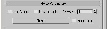
The noise parameter rollout menu is the last option that an be found in the Atmospheric or Render Effect
rollout menu. At first glance it might look a little less powerful than the
standard 3ds max noise Features for volume lights. In fact, its real power
comes from the fact that finalRender uses a standard 3D map to create the noise
structure s in the volume light effect As it uses a standard 3D texture map
everything can be done and adjusted in the materials editor. You just have to
animate the X Y Z offset or rotation to simulate wind etc.
NOTE:
You may only use procedural 3D texture maps to create noise or any other
fractal effects in the light's volume. This restriction is caused by the 3D
nature of volumetric effects.
Use Noise (Volume Light)
Check: this option when you want to use any 3D map to modify the color or
transparency in the light's volume. Remember to use only 3D maps!
Link To Light (Volume Light)
Check this option to lock the noise space to the lights cone, cylinder or
sphere. Animations created with this option on tend to look like solid objects
instead of a real volumetric effect.
Samples (Volume Light)
The amount of samples controls the quality of the final effect. More samples will
create more points in space to analyze the 3D map for color and transparency
values.
Map Button (Volume Light)
Click onto this button to open the Map browser dialog. If you turn the MAP
filter to 3D maps only, this will display 3D maps only and it will make it much
easier to choose a correct map.
Filter Color (Volume Light)
When this option is checked, the color information of the 3D map will affect
the volumes color.
finalRender Global Settings
We suggest that you read the chapter "About finalRender" before you
proceed reading with this chapter about the finalRender parameters and
settings. To understand the settings and parameters of the finalRender
Materials and Global settings a basic understanding of the methods used in
finalRender is essential menu. During the install of finalRender an entry was
added in all available ads max "menu" files to make sure that you
will get a finalRender Globals menu entry regardless of the menu style you've
chosen. From this Quad menu entry you may access the finalRender Global
settings dialog.
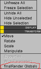
If for any reason the installer didn't add a menu entry to the 3ds max menu
file you may add it manually. To add a finalRender Globals menu entry to the
standard Quad menu follow the steps described below.
1.) Open the "Customize User Interface" dialog of 3ds max.
2.) Select the "Quads" tab, then select finalRender in the Group
3.) Drag and Drop the finalRender Globals action to the right side of the
dialog, placing the action in the Quad menu wherever you want it. Lastly
remember to save your new UI.
finalRender Globals Menu 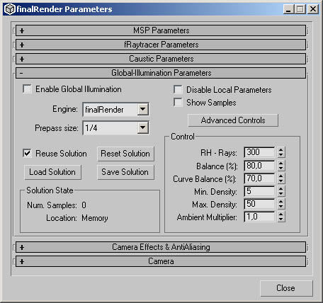
In the finalRender Globals menu you'll find all the necessary settings to
control the appearance and performance of the finalRender raytracer. The main
dialog is divided in several sub sections with each section having its own
individual rollout menu. One of the most important rollout menus is the Global
Illumination Parameters menu. There you will find all the global settings to
handle the various aspects of a Global Illumination rendering. Illustration
FR-03 presents all features and functions available in this rollout menu. Note
that the Advanced Control button must be pressed to reveal the advanced GI
parameters.
Illustration FR-03
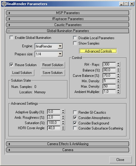
Global Illumination Parameters
Find be low descriptions of all the GI-rollout parameters.
Enable Global Illumination (fR Globals)
![]()
Check this option to enable Global illumination calculations. This feature is
great for debugging purposes as it disables globally all GI calculations.
Engine (fR Globals)
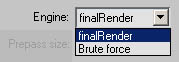
finalRender Stage-0 comes with a choice of two GI-Engines. One rendering engine
is finalRender's highly optimize a Global Illumination raytracing core. The
other option is to calculate a Global Illumination scene with the Brute Force
method. This GI-Engine works completely different from the standard and
preferred finalRender engine, Brute Force uses a much more time consuming
process to calculate the indirect illumination in a scene. Each shading point
will be used to generate a set of hemispheric rays regardless if it makes sense
to do so or not. Images created by this method often show sharp details even on
small structures. A recommended use of Brute Force is for daylight or outside
scenes.
Warning
Be careful when using diffuse bounce values above 2 with Brute Force! The
amount of RH-Rays should not exceed 128 rays on standard PC's.
Example
Computer: processor - Atlon 1 GHz, RAM - 256, MB - MSI K7T Turbo, Video - Riva
TNT2 Ultra.
|
Brute force |
|
Final Render |
Prepass Size (fR Globals)
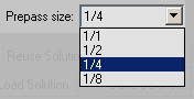
To speed up the Global Illumination render a prepass is per formed by
finalRender. The prepass can be described as an illumination gathering pass.
It's a standard raytracing pass with reduced resolution and shading functions.
By default a quarter (1/4) of the rendering resolution is used to gather the
first illumination values which are then fed into the main Global Illumination
pass.
Tip
A quarter of the rendering resolution is a good starting point for most scenes.
The speed versus quality ratio is good at this size. Smaller sizes tend to
produce more visible artifacts in the rendering, bigger sizes (1/1) will reduce
artifacts the best.
Raise Solution (fR Globals)
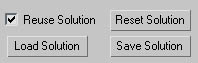
Check this option to make finalRender use a previously saved Global
Illumination solution. No prepass rendering is then needed with this option
active.
Tip
You must not change any light settings or geometry while this option is active
or the rendering will be incorrect as it was based on previous settings.
Changing camera angles is ok though so creating a camera fly through is
possible.
Load Solution (fR Globals)
Click this button to get a standard Load File window. Global Illumination
solution files use the extension GIM. Make sure that you use the correct GIM
file for a given scene or the result maybe random and contain false illumination.
Reset Solution (fR Globals)
Click this button to start a GI-rendering from scratch. Note that you must
reset the GI-solution whenever you do any changes to the lights, materials or
geometry in a scene.
Save Solution (fR Globals)
You may at anytime save a specific GI-solution to your hard drive. Make sure
that you choose a proper name for the GIM file so you can recognize it later. A
GIM file is only valid for a specific scene with specific settings.
Solution State (fR Globals)
The Solution State displays the actual count of GI-Samples along with the k
memory consumption. Location indicates the file name to be used for storing the
samples (GI Solution). When Location is set to memory it means that new sample
s have been reated in a tendering pass and that the actual
GI-solution is different from the solution stored to the hard drive. Those new
samples exist only in memory! If you re set the scene or dose 3ds max all of
the GI-Solution is lost!
Every rendering pass could create new samples, so check this dialog to make
sure that your GI-Solution from your hard drive is still valid.
NOTE
The GI-Solution path is stored along with the scene file and so it's possible
to do a network rendering with a presaved solution file! Make sure that this
path is valid for all machines (i.e. every network PC must have drive
X:\3dsmax\tbaker\hangarscene\). For more information about network rendering
and how to create animations see next chapter!
Animated Global
Global Illumination is a very time consuming process and it is very unlikely
that you can afford to render big animations with pure Global Illumination.
It's not just the render time alone that can be a hut die to get an animation
done with GI. finalRender vises a highly optimized stochastic sampling method
to detect light on other surfaces in a scene. Each shading point may create
hundreds of random hemispheric rays (RH-Rays) and every single ray may detect different
illumination levels on other surfaces and so on. To get de an images and the
best performance possible random directions and random rays must be used. As
this randomness is dependent on thousands of conditions and situations every
frame will create different re suits. For still images each frame rendered will
be "perfect" However, for animations it will be a big mess, even the
slightest changes in the GI-creation process will be visible as constant noise
throughout the animation.
So how would anyone be able to render animations with GI?
This problem doesn't just effect finalRender, all GI-based rendering systems on
the market behave like this. No one has found a good solution to this problem
right now. Some claim that they you have solved the problem but those solutions
are based on brute force rendering methods. Some might use 5000 RH-rays and so
your animation result will be pretty stable With approx. 5000 RH-Rays the
randomness is nearly eliminated as every sample will get the correct result for
the scene with no changes over various frames. The problem is you don't.
Do it the clever way!
finalRender comes with many tools and one of them is very useful in
streamlining animations with GI. tBaker allows you to bake lighting situations
into texture maps including GI solutions. The workflow for a GI rendering might
look like this:
1.) Render the GI for every object in the animation for the "perfect"
viewpoint
2.) Bake each light situation for every static object (walls, floors and so on)
3.) Render the animation with standard directional fights and the tBaker
materials
It will need some preparation and planning to create GI animations like this,
but the results you will get with these methods are unmatched.
Disable Local Parameters (fR Globals)
![]()
Check this option to disable any local settings any material might have. This
is useful for debugging purposes as it allows you to render the scene without
any interaction between the local settings.
Show Samples (fR Globals)
![]()
This is the most important switch in finalRender! If you want to get good
results out of finalRender you must use this switch!! If s the only way that
you can tell if a rendering is going to be good or bad and where you can
enhance your settings.
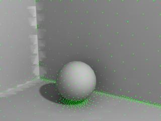
Turn this setting on to see how the samples are produced or detected by
finalRender. In the image to the tight you can see where the samples ate placed
please note that it's not just the position but also the size of the samples
that tells you how a rendering might rum out. In general if you start to see
samples getting too big, the Max Density value is much too low for the scene.
For more information about using the Show Samples button check out the tutorial
"My very First GI-rendering".
Advanced Controls (fR Globals) ![]()
Press this button to reveal the advanced settings. Advanced settings are
usually needed for complicated scenes. Usually you don't need to use these
settings often.
RH-Rays (fR Globals)
![]()
Random Hemispheric Rays (RH-Rays) are an essential part of Global Illumination
rendering. The amount of RH-Rays used has a direct relationship to the quality
of the final image. Using more rays will create smoother and better images,
assuming that the sample distribution in the scene is good enough. More rays
are needed in scenes that have less or no direct light; e.g. self-illuminated
materials serving as a replacement for area lights. RH-Rays are ere ate din a
hemispheric dome like manner from each sample point. Every single RH-Ray that
hits another surface will create another.
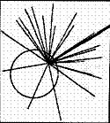
Balance % (fR Globals)
![]()
This controls the balancing between the Minimum Density and the Maximum
Density. A Balance of 100% means that every shading point will be used to
detect GI specific data in a scene. Specific data can include nearby objects,
intersecting geometry but also contrast changes in illumination levels. You
need to adjust the Balance value whenever you start to see missing parts that
are not covered by sample s or seeing samples that are too big. A good example
of this is when shadows are missing or jagged. To be careful as increasing this
value even in small amounts will result in an explosion of the total samples
created by final Render. You need to "balance" all three parameters.
Curve Balance % (fR Globals)
![]()
Curved or bumpy surfaces are a classic GI-killer Imagine a surface with small
canyons. The lower points of the curves will ear up many of those RH-Rays and
many of them won't escape from this Black Hole! Even worse, the "near
object detection" condition will run wild as it detects each ray created
by a nearby object and it will start to create more samples to compensate for
that. To help you in avoiding these problems we have added the Curve Balance %
parameter. Decrease this parameter to make the finalRender engine ignore curvy
or bumpy surfaces. Read the chapter The Curvy Surface Problem1 for mo re
information.
Mm. Density (fR Globals)
![]()
Defines the minimum density to be used when placing sample points in space.
Each sample point will be within this distance of each other.
Tip
The distance you are able to set with Min. Density is calculated relative to
the scene boundary. A really big scene will need bigger Min. Density values. Be
careful with these settings, if say you removed an object that was 100,000
units away, the scene would suddenly be only 500 units wide, if you kept the
original Min. Density you would face problems, as the density has now increased
by a factor of 200!
Max Density (fR Globals)
![]()
The Global Illumination engine that finalRender uses has several optimization
approaches to get the best possible render times. One approach is to avoid the
creation of unnecessary rays. This optimization is achieved by creating more
rays only where they are needed. Reasons that result in more sample points (and
this means more rays later) include nearby objects, intersecting geometry and
large change sin contrast on a surface. This is controlled by Max. Density
which sets the maximum density allowed for a scene. In corners, for example,
densities will increase automatically as more rays are needed. Increase this
parameter to get higher densities of sample points in important areas of the
scene.
Tip
Use this with the Show Samples feature of finalRender! This is the only way to
see where the samples are being placed by the GI-engine. If you start to see
big green samples covering large areas of the scene you will need to increase
the Max. Density.
Ambient Multiplier (fR Globals)
![]()
Use this setting to globally control the indirect light level in a scene.
Increasing this value does not destroy the GI-Solution file, so you can change
this value without the need to reset the GI-Solution. All indirect light values
are multiplied by this factor.
Tip
It's too easy just to use this global setting to make your scene look nice. We
do not recommend this as a solution to get dark scenes brighter, because most
of the time this will reveal image artifacts. The better choice is to model the
scene correctly with a natural distribution of direct light, then use the
global Send and Receive multipliers of the materials instead!
Advanced Settings (fR Globals)
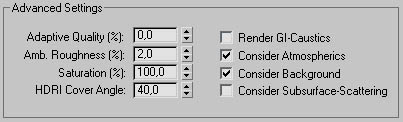
Adaptive Quality % (fR Globals)
Use this setting to activate the creation of adaptive random hemispheric rays
(RH-Rays). If this value isn't set at zero additional rays will be created
whenever the algorithm detects that an illumination level is not correct. An
Adaptive Quality of 100% means that up to 10,000 rays are sent out per sailing
point, though this amount of rays would be the worst case only. The image
quality will improve with an increasing amount of Adaptive Quality.
Important
The algorithm needs to send out a minimum amount of RH-Rays to detect if new
rays are needed For example, if RH-Rays is set to 3 rays and Adaptive Quality
is set to 100% the result will be still very bad and splotchy. A good minimum
amount to start with is a RH-Rays setting of 64 though for some scenes 128 rays
or higher will be needed.
Illustration FR-03 on the left uses no Adaptive Quality (0%), as you can see
the image is full of artifacts when you compare. In to FR-04 on the right which
uses an Adaptive Quality of 100%.
|
Illustration FR-03 |
|
Illustration FR-04 |
Ambient Roughness% (fR Globals)
Our research showed that some images look their best when there is a special
kind of noise visible. Such noise patterns tend to blend away the image
artifacts created by the GI rendering process. The Ambient Roughness value
defines the amount of noise, which will be added in shadow areas or areas of
high contrast. Higher values will create more visible noise.
Saturation% (fR Globals)
Global Illumination calculations are based on physically accurate methods.
Energy is distributed among different surfaces in a scene until all of the
energy is consumed. As an artist you usually don't care about how physically
correct a rendering is if an image looks wrong it is wrong, regardless if the
rendering is mathematically correct or not. To serve your needs as an artist we
have added a Saturation parameter. This parameter allows you to de saturate or
even over-saturate the colors of an image. If you prefer more and stronger
color bleeding increase this value, if you don't like saturated colors turn it
down to zero.
HDRI-Cover Angle (fR Globals)
This lets you control the lighting quality of an HDR-Image. Some HDR-Images
show an enormous range of intensities for each single pixel. Increase this
value to reduce the amount of bright or dark spots in an image. To learn more
about HDR-Images and how you can use them as a light source read the chapter
about High Dynamic Range Images.
Render GI-Caustics (fR Globals)
The Global Illumination method used b finalRender is able to detect all kinds of optical
phenomena. Complex effects like caustic patterns created by refractive or
reflective objects are handled in a single pass. Turn this option on to see
caustic light patterns. Please note that the rendering times will rise
considerably.
Consider Atmospherics (fR Globals)
When checked atmospheric effects are considered in the Global Illumination
pass. Atmospheric effects like Fire Effect or volume fog may be used as a real
volumetric light source in a scene. When turned on a good amount of rendering
overhead is added to the render time.
Consider Background (fR Globals)
To use a background image or a background cobras a light source that adds some
amount of indirect light to the scene check this option. If turned off all rays
hitting the background will be treated as the had found a black color.
Consider Subsurface Scattering (fR Globals)
Turn this option on to consider sub-surface light scattering in the Global
Illumination pass. When off sub-surface light scattering is only considering
direct light sources.
Ray tracer Parameters 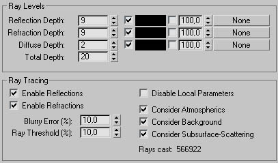
As you should know by now finalRender is a real raytracing system, all major
settings affecting the raytracer performance and quality are found here.
The first section in the raytracer parameters menu is the ray level handling.
The ray level defines the amount of bounces a ray performs or the amount of
refractions or reflections a ray will go through.
Here's an example:
Imagine a wine glass, how many bounce levels would you need to get through the
glass to hit the ground. Without liquid filled in the glass the amount of ray
levels (bounces) needed to get through to the ground would be 5. The first ray
is the first hit on the outer shell of the glass, second is the exit of the
inner shell of the glass, the third is the inner side of the glass, fourth is
the outer back side of the glass and finally the fifth is the background pixel
In this example we didn't take into account any rays that would create
reflections or come from a reflection. If we wanted to see the glass in a
mirror we need to add one more bounce level and so on.
So how deep should the ray depth level bet?
This depends on the type of scene and what kind of objects are in the scene.
Many reflective objects will force a higher setting of the bounce level as
would many intersecting glass objects. You can easily tell that the ray depth
is too low when you start seeing black spots or black areas in glass or mirror
objects.
Reflection Depth (fR Globals)
Here you can set the maximum bounce level a ray should reach before it is
treated as black, or any color you set in the "end color" color
swatch. This parameter affects the reflected rays only.
Refraction Depth (fR Globals)
This is used to change the maximum ray bounce level for refracted /s only If this value is set too low you will start
seeing black spots or black areas in glass objects.
Diffuse Depth (fR Globals)
Global Illumination is a raytracing process in that multiple rays are shot into
the scene and each ray hit creates another set of hundred rays and so on. If
there were no limit to the amount of maximum bounces a ray may create, the
rendering would never stop. This parameter is important in detecting the
correct illumination in a scene. Take a 2 for example, imagine this maze is
created with white walls and one light source only at the end of the maze. To
see some light from the camera at the start of the maze many bounces are
needed, but don't over do it as each bounce level adds extra overhead to the
total rendering time.
Total Depth (fR Globals)
Sets the total ray depth possible, this is calculated by adding up all ray
levels a ray may have created. For example, if a ray had 2 reflections and 10
refractions and also 5 diffuse bounces, the total depth of this ray would be 13
bounces. This parameter is useful in cutting off the other individual ray
depths.
Final Color (fR Globals)
When a ray exceeds the maximum allowed depth (ray level) color must be chosen, by default this final color is
black. Note that the ray doesn't get any color information because the ray
wasn't alto wed to do any more bounces to get to the final color. This makes
sense when assume that the ray has bounced so often that there
is no energy left (color) to add to any coloring of the raytraced pixel. To
manually seta fixed color for the "final ray" heck the first box. If you enable the second checkbox
a texture map, map be used to set the final color of the ray. Any mapping type
can be used for this texture map, but using an environment mapping type only
makes sense. Using texture maps as the final ray color maybe used to get a more
realistic "final ray color" based on the environment colors and the
angle of the ray. You may also set ray colors for the Reflection, Refraction
and Diffuse rays.
Enable Reflections (fR Globals)
To globally rum On or Off all reflections in a scene check this option. This is
great for debugging purposes.
Enable Reflections (fR Globals)
Check this option to globally turn On or Off all refractions in a scene, this
is useful for debugging purposes.
Blurry Error % (fR Globals)
finalRender is one of the first "true" raytracer to bring realistic
diffuse reflections to 3ds max. Base don physically correct raytracing methods
Diffuse or blurry reflections are very processing intensive raytracing effects.
Blurry Error % controls the amount of error allowed for a diffuse reflection
ray. If this parameter is set too high speckles or other kind of artifacts can
be created, keep this value as low as possible for best rendering results.
Ray Threshold % (fR Globals)
This value defines the "selection" threshold for the Blurry Error
parameter. Higher values will create more artifacts in diffuse reflections.
Disable Local Raytracing Parameters (fR
Globals)
Check this option to overwrite all local raytracing settings (reflection,
refraction & Blurry Error).
Consider Atmospherics (fR Globals)
If you-want to see atmospheric effects in ray traced materials (reflections or
refractions), check this option.
Example:
When on a mirror object will reflect a PyroCluster(R) effect or a glass object
may show refracted atmospheric effects.
Consider Background (fR Globals)
When turned off the refracted or reflected rays will not see the background
color or image.
Consider Subsurface Scattering (fR Globals)
Enable this option to render sub-surf are light scattering effects. If this
option is turned off all sub-surf ace light scattering will be disabled.
Rays Cast (fR Globals)
For your enjoyment the number of rays shot is displayed here. If you see huge
numbers there the image better be good!
Caustic Parameters 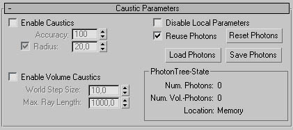
Caustic light patterns, simply called Caustics, are described in detail in the
chapter about finalRender Lights. The section "What are Caustics?"
describes how caustics are created and controlled within finalRender. The
global caustics rollout menu holds all the important parameters and settings
that will affect your whole scene.
Enable Caustics (fR Globals)
Check this option to enable the processing of caustic light patterns. If turned
off no caustic effects will be rendered.
Accuracy (fR Globals)
This global control lets you set the quality or smoothness of a caustic light
effect. This value represents the amount of Photons used to average the
illumination level of an area. Increase this value to get rid f tiny spots or isolated Photons that are away from
the focal point. Accuracy is also available as a local finalRender material
setting, local settings will overwrite the global parameter. For
non-finalRender materials (standard 3ds max materials) the global parameter
will be used. Enable Caustics must be checked to activate the Accuracy
parameter.
Radius (fR Globals)
Defines the radial area in world units where the caustic engine looks for
Photons in the space. Larger numbers will create better more realistic images.
As you can imagine though searching in a bigger area and averaging such an area
will take longer to render! When the checkbox of Radius is unchecked an
unlimited search radius will be used! For faster renderings you must keep this
value as to was possible. Enable Caustics must be checked to activate the
Radius parameter.
Note:
You can tell that the radius value is too tow when you start to see single
spots or splashes of lights where the shouldn't be. To get rid of these increase the radius.
Enable Volume Caustics (fR Globals)
Enable this checkbox to render! Volume caustic light effects. If this parameter
is turned off no volume caustic light effects will be rendered.
Enable Volume Caustics (fR Globals)
Sets the amount of volume steps through the 3D volume. Be careful! Lower values
will result in long render times. We suggest using values between 3 and 15.
This parameter is active only when Enable Volume Caustics is on.
Tip
You can tell that the Step Size value is too high when you start seeing an
offset between the volume caustic ray and the surface caustic effect. In this
case reduce the Step Size.
Enable Volume Caustics (fR Globals)
3ds max light sources do not have "an end". The ray of light created
by a 3ds max light source has an unlimited length. As you can easily imagine
"unlimited" is not good for stepping through abounding volume because
it would take an unlimited time to finish this stepping. Max. Ray Length
defines a fixed length for a light ray, if a volume caustic effect is cut off
along its path increase this value.
Disable Local Parameters (fR Globals)
Check this option to turn off all local caustic settings set in finalRender
materials.
Reuse Photons (fR Globals)
Turn on this parameter to re-use previously generated Photons or Photons stored
to the hard drive. Keep an eye on this setting! If you forget to reset the
Photons after you changed a light source or material properties you will get
the wrong rendering result. Changing the camera or moving objects that do not
interfere with the caustic effects of other objects is possible though.
Load/Save Photons (fR Globals)
Press the relevant button to load or save a finalRender photon file. A photon
data file includes all the data needed to restore the correct caustic effect
without re-processing the Photons again.
Reset Photons (fR Globals)
Press this button to dear the memory from any Photons created so far. This is
only necessary when Reuse Photons is active and you've changed some important
scene properties.
Photon Tree State (fR Globals)
This section of the caustics rollout menu display the current state of the
Photon tree. When the Location is set to "Memory", new Photons have
been added to the Photon tree (database). If you do not wish to lose all of the
processed Photons then use the Save Photons option. When Location is set to a
filename (e.g. X:\max4\Photons\myphotons.pho), make sure that this path name
can be accessed by all network machines or you won't be able to use the photon
file in network rendering model.
Camera Effects & Anti Aliasing 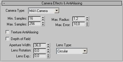
finalRender is a full-blown raytracing system offering many raytracing.
specific functions and rendering effects. The Camera Effects & And Aliasing
rollout menu gives you access to the view dependent raytracing parameters.
Camera Type (fR Globals)
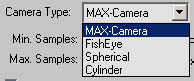
finalRender supports various camera types that are specific to raytracing. If
you choose any other camera type other than the MAX-Camera the finalRender ray
tracer is activated for the rendering. These are the camera types below:
1.) MAX-Camera, the standard scanline rendering camera of 3ds max.
2.) Fish Eye Camera, this camera is based on a real Fish Eye lens.
3.) Spherical Camera, real 360-degree camera.
Please note that all raytracing. camera types (2-4) are raytracing. only
cameras. You need to set a proper Min. Samples and Max. Samples value to get
good AA. Raytracing is considerably slower than scanline rendering. A
combination of both scanline and raytracing is not possible with this special
camera types.
Min Samples (fR Globals)
Doing proper Anti Aliasing (AA) is one of the most important aspects of any modem
raytracing system. finalRender uses adaptive (AA) functions to detect where
extra rays are needed. Min. Samples defines the minimum amount of rays to be
used! when an (AA) condition is detected.
Max. Samples (fR Globals)
finalRender uses advanced adaptive algorithms to detect (AA) situations in a
rendering with unmatched speed and quality. In theory finalRender would be able
to do (AA) processing fully automatic ally However, as rendering speed is
always an issue a maximum amount of (AA) rays can be defined. finalRender will
not create more (AA) rays than set in Max. Samples.
Texture Anti Aliasing (fR Globals)
Texture Anti Aliasing maybe turned on or off for standard ads max materials.
This option should also be turned on when rendering reflections or reflections
with finalRender materials. Each finalRender material offers the option to do
local (AA) which is restricted to objects using this material only. We
recommend you use this global setting instead of the local material based
version.
Attention
When texture Anti Aliasing is turned on Min. Samples and Max. Samples controls
the AA quality.
Max. Radius (fR Globals)
This parameter defines the adaptive search radius around each screen pixel.
Bigger radius values may increase render! times because of the possibility of
finding more (AA) pixels is increased now. Also by increasing Max. Radius the
blur of the image also increases.
Max. Error (fR Globals)
Defines the maximum error allowed to treat an AA situation as "good"
before new rays are shot through the screen pixel. Bigger Max. Error values
might reduce render! time but can also decrease image quality. There is no real
rule of thumb for this setting every scene has different (AA) requirements and
so you may need to adjust this setting for each scene you are working on.
Depth Of Field (fR Globals)
Many artists think that the only "real" way to render a proper DOF
effect is by raytracing the scene. Everything else is just a fake and
"will fail to work properly in many situations. To use finalRenders
physically oirect DOF torn this option on.
Attention
The smoothness of the DOF effect depends on many parameters. Mainly it's the
amount of rays used for AA (Min. and Max. Samples). For good DOF re suits you
need to increase the Min Samples considerably. The camera aperture value also
plays an important role for the DOF effect Increasing aperture sizes will
increase the blur of the final rendering.
Lens Rotation (fR Globals)
finalRender offers additional camera lens effects in conjunction with DOF Re al
movie cameras show a very interesting effect when shooting in dark situations
with a high DOF blur. Bright spots, which are way out of focus will show up as
blurred circles, triangle s or any other kind of shape that is produced by the
optical properties of the lenses used in the camera. To control the orientation
for non-circular blur artifacts use this setting Lens Rotation defines the
angle of rotation for the camera blur artifacts.
Note:
Rotating a circle does not make sense!
Lens Exp. (fR Globals)
Increase this value to get brighter exposure and more visible camera blur.
Lens Type (fR Globals)
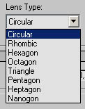
finalRender supports many different lens types to generate camera blur
artifacts. Choose any shape for the blur artifacts from the drop down list of
lens types. Camera blur artifacts are only visible in blur red areas, note that
the size of the camera blur artifacts will increase with the blur of the image.
Camera
This rollout menu is used whenever a turn MAX-Camera type is chosen. The
formula used by finalRender to create a fish eye rendering is based on a real
fish eye camera lens system.
Distortion (fR Globals)
This setting defines the viewing angle of the hemispheric glass lens. Note that
fisheye must be selected under camera type. An angle of 180 degrees defines a
"full" visible panorama. All objects in front and to the sides of the
camera are visible and will be distorted (bend) towards the edges of the lens.
Zoom (fR Globals)
The standard ads max camera settings are disabled whenever a special lens type
is chosen. Increase the Zoom value to enlarge the visible part of the image.
MSP Parameters 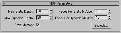
finalRender uses state of the art raytracing acceleration technologies, the
core acceleration system in finalRender is called MSP-Tree. This proprietary
"depth sort" system speeds up the raytracing process a great deal.
The technology be hind this NISP-Tree is quite complex and would take several
hundred pages to describe the ideas and enhancements of this technology. We
recommend that you leave the parameters untouched, as you don't really know
where to dial the parameters in. The default settings should work for 90% of
all scenes you might create. However, there are some situations where you might
need special adjustments to the MSP-Tree. Such situations are usually where there
is a memory problem, such as an enormous high polygon count or heavy object
motion blur in the scene. All this effects the triangle sorting mechanisms and
sometimes the MSP-tree might run into a dead end by asking for more and more
memory.
Max Static Depth (fR Globals)
One idea is to accelerate the intersection testing of rays in space to find
them a lot fasten Usually each ray must be "traced" and rested
against all kinds of situations (intersection with faces, volumes, refraction,
reflection etc.). This is where the MSP-Tree comes into play where the whole 3D
scene is subdivided into quadrants. It's easier and faster to find a quadrant
compared to finding a single face. The Max Depth parameter controls how often
the 3D scene is subdivided into smaller quadrants. Higher values will result in
a much bigger MSP-Tree, which will use more memory. Large numbers will improve
render time on scenes with high object counts.
Max Dynamic Depth (fR Globals)
finalRender creates two separate acceleration trees. One tree holds the static
faces, these are faces that do not move, change or deform in an animation. The
other, the dynamic tree holds all the faces that are changing in an animation.
The advantage of dividing those object types into different acceleration trees
is that only the triangles that change from frame to frame must be recalculated
for each frame.
Save Memory (fR Globals)
Saving memory is always a good idea and we recommend to keep this option
activated on 32-bit systems (Pentium 3, 4 and AMD Thunderbird etc.). You might
already know that finalRender is ready for 64-Bit CPUs like the Intel Itanium.
Software running on 64-Bit CPU's is able to access easily 16 GB of All or even
more, on such a system you would be more than willing to trade the memory consumption
of a MSP-Tree for endless scalable rendering speed!
Faces Per Static MCube (fR Globals)
This sets the maximum number of faces that should be collected in one MCube
quadrant. Increase this value only when there are complex objects with high
poly counts in the scene. Higher face counts will reduce the memory consumption
of the MSP-Tree. When rendering scenes with more than 200,000 polygons we
suggest you use 32 faces per MCube.
Faces Per Dynamic MCube (fR Globals)
finalRender also differentiates between static triangles and deforming or
moving triangles. You may set the maximum number of dynamic faces that should
be collected in one MCube quadrant. Increase this value only when there are
complex objects with high polygon counts in the scene. Higher face counts will
reduce the memory consumption of the MSP-Tree. When rendering scenes with more
than 200,000 polygons we suggest you use 32 faces per MCube.
Exclude (fR Globals)
Click the Exclude button to open a standard 3ds max Exclude/Include dialog.
This dialog enables you to exclude objects from the MSP-Tree completely so that
the
do not exist in the MSP-Tree.
Attention!
The Exclude/include dialog that pens up has nothing to do with the light source
Include/Exclude function of ads max. Bear this in mind, settings like
Illumination. Shadow Casting and the option both have no influence at all The
only flung that is used from this dialog is the list of objects.
Material Type: finalRender 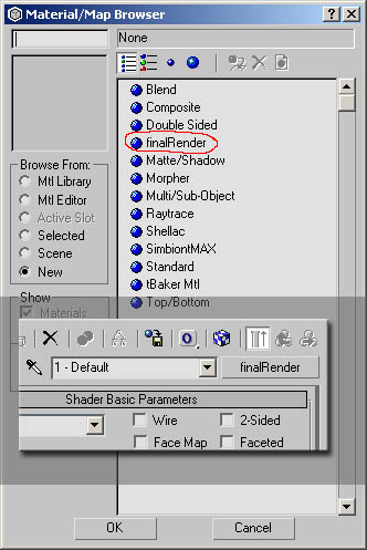
All the power of
finalRender is implemented in 3ds max as a new material type. There is no need
to add or change the 3ds max scanline render to activate the advanced
raytracing or Global Illumination features. A hybrid rendering approach gives
you the ultimate rendering and raytracing power be cause each part is activated
fully automatically and is transparent to the user. All objects using standard
3ds max materials will render lighting fast as before without any restrictions,
only objects using finalRender materials will use raytracing methods to render
those objects.
Whenever you plan to use advanced Global Illumination functions make sure that
there is at least one finalRender material is present in the material editor
slot. Remember that there is no need to assign the finalRender material to the
scene, all f it's functions can be used with standard 3ds max
materials. Another way to use finalRender raytracing features, without any
material changes and settings, would be to use the right quad menu of 3ds max.
Any global property setting can be activated and you can even use Global
Illumination or Caustic effects with standard 3ds max materials. However,
remember that you must properly set up a 3ds max scene that uses standard materials
only. All object properties (right-click on each object) must be
changed/adjusted to re present the correct behavior (send GI, receive GI etc.),
you should also make sure that not all lights are photon emitters.
We added this support for standard 3ds max materials to make life easier when
handling your old scenes that can't be changed easily. We don't advise you make
this your normal scene set-up though! We strongly recommend you using
finalRender materials instead of standard raytracing or standard 3ds max
materials. The material converter utility makes your life easier when
converting "old" scenes to be finalRender scenes. As finalRender
materials are much more sophisticated than standard materials they offer
effects and controls impossible to get with any other material.
Keep in mind that effects like Global Illumination can modify the ambient value
of the material to achieve the proper lighting level. Standard materials that
do some sort of combining multiple materials into one (e.g. Shellac) may possibly
interfere with a physic ally correct rendering approach. You will end up using
all of the material tricks you have before just don't be surprised if the
result is a little different from what you expect it to be.
finalRender Material Settings
|
The finalRender material type is in some ways identical to a standard
3ds max material type. The Basic Shader Parameters rollout menu for example
is identical to any standard 3ds max material. All the settings you'd find in
this rollout menu are explained in the 3ds max manuals. Other rollout menus
identical to 3ds max standard materials are: |
|
|
finalRender Parameters Rollout menu
Illustration FR-05
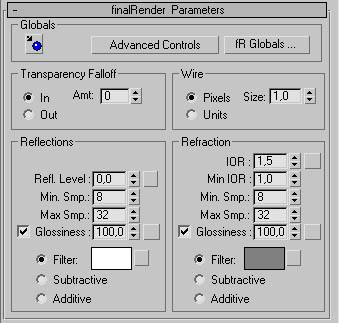
All the important features of finalRender can be accessed in the finalRender
Parameters rollout menu. This menu will show the most important default
parameters (see Illustration FR-05). As soon as you press the Advanced Controls
button the rollout menu expands and you will see even more features to play
with! For now though we will just deal with the default menu layout.
Convert Material Icon (fR Material)
Press this icon to activate the finalRender material converter. As soon as this
icon is pressed 3ds max goes in to pick mode where you may pick any object in
the scene to transfer its material properties. Material conversion isn't a
trivial process because 3ds max has such a powerful material editor and the
complexity of a single material maybe extreme. Our tests showed that the
material conversion works best with standard materials that do not use any
raytracing or 3rd party material plugins. One restriction is that a finalRender
material can't be converted into a different material type. A converted
material will include all shader parameters along with the various texture
slots and sub-textures.
Advanced Controls (fR Material)
Activate this button to reveal the Advanced Parameters section of the rollout
menu. There you will find extra material parameters that usually makes life
much more fun. To learn more about the advanced parameters see the relevant
chapter.
fR Globals (fR Material)
Click this button to get the Globals menu of finalRender. Note that there is
only one Globals menu in finalRender, this is the same menu you can get when
you right-click with the standard quad menu.
Transparency Falloff (fR Material)
This section is identical to the standard 3ds max materials, it lets you
control the opacity falloff for a transparent material. When In is checked the
transparency increases towards the inside of the object, as with a glass
bottle. In contrast when Out is enabled the transparency increases towards the
outside of the object, similar to cloud of smoke. Amt. defines the maximum
amount of transparency for either the In or Out areas. Note that the overall
opacity is still controlled by the opacity spinner.
Important Opacity in finalRender works
differently from standard 3ds max materials! In finalRender, opacity controls
the amount of refraction (transparency) an object has. For example, to get a
proper glass or refractive effect you would set the opacity amount to 50 along
with a change of the filter color.
Wire Menu Section (fR Material)
This menu section is identical to those found in any of the standard 3ds max
materials. It lets you define the wire frame thickness and also lets you set
the line thickness in pixel size or in absolute world coordinates.
Refl. Level (fR Material)
Sets the amount of reflection a surface has. Higher numbers will make the
object behave like a perfect mirror.
Important
finalRender behaves like 3ds max when mixing colors or calculating reflections.
To create a surface that behaves like a 100% perfect mirror, you must
paradoxically set the reflection level to 50% and the filter color to white
(RGB = 255,255,255). With this setting you can control the reflection amount by
changing the filter color to a black color or a white color. Reflection Levels
be low 50% or above 50% will "feed in" the diffuse color amount f the material.
Or in other words, finalRender defines a reflection as a component of the
Filter Color, the Diffuse Color and the Reflection Level. The Filter Color and
Diffuse Color is balanced by the Reflection Level.
Min. Samples Reflection (fR Material)
Used for blurry reflections only. This parameter sets the minimum samples to be
used to render blurry reflections. finalRender uses a highly adaptive algorithm
to calculate proper blurry re flections. Blurry reflections are a 100%
distributed raytracing effect, where multiple rays are sent out into the scene
to detect the correct surface color. Is with all other distributed raytracing
methods (GI for example) the amount of processing power needed to render such
effects is enormous. To be able to render such effects with current processors
finalRender uses highly adaptive algorithms to reduce the total amount of time
to calculate these effects. There must be a certain amount of minimum rays to
be sent out from the object's surface to detect if more rays are needed. Min.
Smp. plays an important role as it defines the render quality to wards the
lower end of this effect. If this parameter is set too low, visible grain will
appear in the blurry reflections. To reduce this grain you must increase the
Min. Smp. amount.
Max. Samples Reflection (fR Globals)
This is used for blurry reflections only. This parameter is part of the highly
adaptive approach to render blurry re flections in finalRender. Max. Smp.
controls the higher end of this effect. To get nice and smooth blurry
reflections, which are physically correct a certain amount of rays must be sent
out from each point on the surface of the object. To avoid render errors and a
grainy look increase this parameter as high as feasible. Setting this parameter
with high numbers isn't as critical as it is with Min. Smp. For example, if
Max.Smp. is set to 128 and Min.Smp. is set to 16, each point on the surface of
the object is shoo ting out 16 rays into random directions (the angle is
controlled by Glossiness). Whenever the algorithm detects an error in the
calculation of the blurry result, extra rays are sent out with an upper limit
set in the Max.Smp. The worst case would be that 128 extra rays are sent out to
get the correct blurry result (a smooth image).
Glossiness Reflection (fR Material)
When checked, the glossiness value of the Shader Basic Parameters is
overwritten with the value found here Glossiness defines the amount of blur for
the reflective part of the surface. You need to increase this value to make the
reflections sharper. You can also use a texture map in the Refl. Glossiness
slot to control this effect, a black pixel in the texture map would use a
Glossiness value of aero while a white pixel would use a Glossiness value of
100.
Note:
Blurry reflection simulates a diffuse surface, objects nearby appear to be much
sharper than objects farther away. This is physically correct behavior as the
rays dissolve much more by distance.
Filter, Subtractive, Additive Reflection (fR
Material)
Select Filter to filter the reflected rays with the color found in the adjacent
color swatch. A filter color may be a fixed RGB value or a texture trap, sec
the description of the finalRender map sots for more information. When
Subtractive is selected the diffuse color will be used as base color and the
reflected ray color will be subtracted from it. This usually results in a much
darter reflection. Additive of course does the opposite of subtractive, the
reflected ray color is added onto the diffuse color.
IOR (fR Material)
The Index Of Refraction is a real world material property that defines haw much
a ray is bent towards or away the initial entry point.
In the real world the IOR results from the relative speeds of light through the
transparent material. Typically this is related to the object's density. The
higher the IOR the denser the object.
Here are some examples of common IOR values:
|
Vacuum 1.0 |
Air 1.0003 |
Water 1.333 |
Glass 1.5-1.7 |
|
Diamond 3.419 |
Ice 1.309 |
Alcohol 1.329 |
Salt 1.544 |
|
Quartz 1.553 |
Rule 1.770 |
Emerald 1.570 |
Topaz 1.610 |
You can also use a map to control the index of refraction IOR maps always
interpolate between Min. IOR (see below) and the setting in the IOR parameter.
A white pixel in the texture map will use the IOR value from this parameter and
a pure black pixel in the chap will use the Min. IOR value.
For example, if you set the IOR to 3.55, Min. IOR to 1.0 and use a
black-and-white Noise map to control IOR The IORs rendered on the object will
be set to values between 1.0 and 3.55 and so the object will appear denser than
air. If on the other hand, you set the IOR to 0.5, then the same map values
will render between 0.5 and 1.0, as if the camera is under water and the object
is less dense than the water.
IOR (fR Material)
Sets the minimum IOR value to be use d when a texture map is controlling the
IOR values of an object Black pixels in the texture map will be the IOR value
set in this parameter.
Min Samples Refraction (fR Material)
Used for blurry refractions only, this parameter sets the minimum samples to be
used by the raytracing engine to render blurry refractions. Blurry refractions
are a 100% distributed raytracing effect where multiple rays are sent out into
the scene to detect the correct surface color. There must be a certain amount of
minimum rays to be sent out from the objects surface to detect if more rays are
needed. Min. Smp. plays an important role as it defines the render quality
towards the lower end of this effect. If this parameter is set too low visible
grain will appear in the blurry refractions. To reduce this grain you must
increase the Min. Smp, amount.
Max. Samples Refraction (fR Material)
Used for blurry refractions only. Max, Smp, controls the blurry effect towards
the higher end of this effect. To get nice and smooth refractions, which are
physically correct a certain amount of raps must be sent out from each point of
the surface of the object To avoid render errors and a grainy look increase
this parameter. Setting this parameter to high numbers is not as critical as it
is with Min.Smp. For example, when Max.Smp is set to 128 and Min.Smp. is set to
16, you know that each point on the surface of the object is shooting out 16
rays into random directions (the angle is controlled by Glossiness). Whenever
the algorithm detects an error in the calculation of the blurry result, extra
rays are sent out with the upper limit being Max.Smp. The worst case would mean
that 128 extra are sent out to get the correct smooth result.
Glossiness Refraction (fR Material)
When checked the glossiness value of the Shader Basic Parameters is overwritten
with the value found here. Glossiness defines the amount of blur for the
refractive part of the surface. Increase this value to make the refractions
much sharper. You can also use a texture map to control this effect, a black
pixel in the texture map would use a Glossiness value of zero while a white
pixel would use a Glossiness value of 100.
Note:
Blurry refraction simulates a diffuse and transparent surface where objects
near by will appear to be sharper than objects farther away. This is a
physically correct behavior as the rays disperse more with distance.
Filter, Subtractive, Additive Refraction (fR
Material)
Select Filter to filter the refracted ray with the color found in the color swatch.
A filter color may be a fixed RGB value or a texture map. For more details
about using a texture map see the description of the finalRender map slots.
When Subtractive is turned on, the diffuse color will be used as base color and
the refracted ray color is subtracted from it. This usually results in a much
darker refraction. Additive does the opposite of subtractive and the refracted
ray color is added to the diffuse color.
Advanced finalRender Parameters
Complete Rollout menu (side by side) including advanced controls.
|
|
|
|
Some
users map jump up and down with joy when they see the advanced parameters,
others might be confused with so many controls to fiddle around with This is
why finalRender hides by default the advanced parameters in the rollout menu.
Only when you press the advanced button will you see the rollout menu as above.
If you don't want to mess around with these settings better leave them hidden
until you have 2 need for using them.
Split (fR Material)
This parameter is the default selection. Raytracing reflections and re
flections can be done in many ways. The easiest way to create a reflection is
by reducing everything to one single ray and a perfect surface, this gives us
the folio wing perfect reflection term: Incoming ray angle equals outgoing ray
angle. To get the old style computer graphics look reflections/refractions keep
this default setting.
Advanced Fresnel (fR Material)
In the description of Split we already explained that raytracing a reflection
or refraction isn't as easy as one would want it to be. Messier Fresnel
discovered that many surfaces do not be have eke a perfect mirror, in fact most
surfaces behave completely differently! To explain things in simple terms: A
reflection or refraction changes intensity based on the viewing angle. It is
said that towards the edges the reflection or refraction gets stronger and in
the direct viewing path (perpendicular to the camera) there is no reflection at
all. This method is great to create surfaces like car paint or coated surfaces
of any kind. Activate the Advanced Fresnel checkbox to get the effects
described above.
Important
Advanced Fresnel uses the Fresnel IOR setting (see the Fresnel IOR description
be low) to control the amount of reflectance or how refractive an object is
when it's in the perfect viewing angle (perpendicular to the camera).
Metallic (fR Material)
When checked a more complex multi axis Fresnel approach is used. Metallic
surfaces like gold or silver create specific highlights and halos on the
surface depending on the viewing angle. This spectral light scattering is
simulated by this function. Further spectral light scattering options are
available in the spectral menu section.
Fresnel IOR (fR Material)
The Fresnel IOR is used to decide at what angle the reflection or refraction
should reach its maximum. Increasing this value above 4 will bring back the
reflections/refractions as seen from the perfect viewing angle. Reducing this
amount will show reflections on the outer edges of the object only.
Blur Reflections/Refractions
Check this option to activate the advanced reflection/ re fraction blurring.
This function enables you to use less samples for blurry reflections and
refractions. By using cebas advanced "ULTRA BLUR(TM)" technology,
blurry reflections and re tractions render up to 100 times faster than be fore.
However, some restrictions apply to this technology it is not possible to
render blurry reflections seen from mirrors or other blurry objects. The same
restriction applies to refractions.
Note:
The standard Global Illumination prepass rendering mode is used to prefect data
for the final "ULTRA BLUR" rendering. The size of the prepass
rendering affects overall render time and quality. For pure raytracing scenes
without GI, we suggest to use 1/2 the size of the original rendering.
Advanced Reflection Control
The advanced Reflection control setting handles all aspects of reflections and
how they appear in the rendering. Refraction and Reflection use similar
settings and each component maybe adjusted independent.
Tip
By using the Near and Far range function for reflective and refractive
materials in a scene, you may be able to bring down rendering times when many
reflective objects are in the scene. As soon as an object is fully dark (out of
the far range) the rays won't be processed any further (multiple bounces).
Absorption Reflection (fR Material)
Check this option to define an absorption factor for rays entering dense media.
In the case of a reflective material, absorption defines the decay of energy
applied to rays traveling through space away or toward the reflective object
(usually the rays travel through dear air). You might know that even air
absorbs a fairly high amount of energy, especially when you use the absorption
values of air from a big city. Usually the absorption of light rays is
dependent on the wavelength of the light and the media it enters (e g. on
sunset). Increase Absorption to make light lose energy much faster as it
travels a way or towards a reflective material.
Near Start, Near End (fR Material)
Near Start sets the distance at which the reflection begins to fade in. Near
End sets the distance at which the reflection reaches its full value.
To enable this effect along with the ranges check the radio button next to Near
Start.
Far Start, Far End (fR Material)
Far Start sets the distance at which the reflection begins to fade out. Far End
sets the distance at which the reflection isn't visible (black) anymore.
To enable this effect along with the ranges check the radio button next to Far
Start.
Decay Reflection (fR Material)
Decay is an additional way to make a reflection intensity reduce over distance.
There are three trees to choose from.
None
Applies no decay. The reflection maintains full strength from its surface of
the object to infinity, unless you turn on far attenuation.
Inverse
Applies inverse decay. The formula is "reflect energy = Dl/D", where
Dl is the distance of the rays from the surface of the reflective object, if no
attenuation is used, or the Near End value of the reflection if Attenuation is
used. D is the distance of the surface of the reflection from Dl.
Inverse Square
Applies inverse-square decay. The formula for this is (Dl /D^2). This is
actually the "real-world" decay of light.
Tip
The point at which decay begins depends on whether or not you use attenuation.
With no attenuation, decay begins at the surface of the reflective object. With
near attenuation, the decay begins at the Near End position. Decay multiplies
fir attenuation. Once the beginning point is established, the decay follows its
formula to infinity, or until the ray itself is cut off by the Far End
distance. The distance between Near End and Far Start does not scale, or
otherwise affect, the apparent ramp of decaying reflection.
We recommend to use at least a Far Range to make sure that the dimming
calculation isn't performed until end of time. As you might know,
mathematically it is not possible to get a zero amount of intensity by using
the inverse and inverse square function.
Reflect Material-ID (fR Material)
Check this option to make the Material ID visible in reflections. This can be
used to apply a glow effect or any other video post effect on objects seen in
reflections.
Absorption Refraction (fR Material)
Check this option to define an absorption factor for rays entering dense media.
You might know that even clear glass absorbs a fairly high amount of energy.
Usually the absorption of light r ys is dependent on the wavelength of the light and the
media it enters. Increase Absorption to make light lose energy much faster as
it enters a medium.
Near Start, Near End (fR Material)
Near Start sets the distance at which the refraction begins to fade in. Near
End sets the distance at which the refraction reaches its full value.
To enable this effect along with the ranges, check the radio button neat to
Near Start.
Far Start, Far End (fR Material)
Far Start sets the distance at which the refraction begins to fade out. Far End
sets the distance at which the refraction isn't visible (black) anymore.
To enable this effect along with the ranges, check the radio button near to Far
Start.
Decay Reflection (fR Material)
None
Applies no decay. The refraction maintains full strength from its surface of
the object to infinity, unless you turn on far attenuation.
Inverse
Applies inverse decay The formula is "reflect energy = Dl/D", where
D1 is the distance of the rays from the surface of the refractive object, if no
attenuation is used, or the Near End value of the refraction if Attenuation is
used. D is the distance of the surface of the refraction from Dl.
Inverse Square
Applies inverse-square decay. The formula for this is (Dl/D^2). This is
actually the "real-world" decay of light.
Translucency (fR Material)
Check this option to enable finalRender to calculate physically correct
illumination on semi transparent objects. This includes transparent shadow
casting and light distribution on back faces. Illustration shows a black lit
leaf note how the light is spread properly from the back of the object. The
same scene without translucency turned on (standard 3ds max), will show a pure
black leaf.
Note:
Standard 3ds max materials are not able to properly render illumination of semi
transparent objects, a shadow cast onto a semi transparent object (a curtain or
leaf for example) will not show up. Highlights though are handled correctly by
standard 3ds max materials.
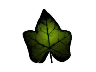
Internal Reflection (fR Material)
When checked internal reflections, found very often in glass objects, are
calculated. This option could increase render time to some extend but the image
will look much more realistic.
Note:
This option might also produce an effect known as Total Internal Reflection.
This happens when a ray bounces between two or more faces around and can't
escape the object. In the re al world this is not a problem as there are enough
rays produced by Mother Nature. If you get into a situation where a ray bounces
back and forth forever, an infinity loop would be created. finalRender avoids
this situation by stopping the ray after the maximum ray depth (bounce level)
is reached.
Refract Material-ID (fR Material)
Check this option to make the Material ID visible in retractions. This can be
used to apply a glow effect or any other video post effect on objects seen in
retractions.
Reflection Maps (fR Material)
This section of the advanced rollout menu uses identical settings found in 3ds
max standard materials. To learn more about the reflection mapping features of
3ds max, check out the online manual.
Note:
Theses settings will effect reflection maps (textures).
Align to Object UV (fR Material)
Check this option to "link" the Anisotropic effect to the objects
surface by using the UV coordinate system of the surface. This will create a
view independent anisotropic effect.
Align to Camera (fR Material)
Check this option to "link" the Anisotropic effect to the camera
view. Whenever the camera changes, this effect changes, too.
Anisotropy (fR Material)
Anisotropic reflections are created with blurry reflections only. This effect
simulates micro facets on a surface, usually found on brushed metal surfaces.
Reflection rays are characteristically distorted to a preferred direction and
this results in a tapered stretched look of the reflections. Illustration FR-06
shows a blurry reflection without Anisotropy and illustration FR-07 shows an
example of the Anisotropy effect at 100%.
|
illustration FR-06 |
|
illustration FR-07 |
Orientation (fR Mater id)
Change this parameter to define the orientation of the Anisotropic effect. The
orientation is defined relative to the surfaces UV coordinate. In the
illustration FR-08 you can see a Anisotropic reflection with a orientation of
45o and illustration FR-09 shows an orientation value of 135o.
|
illustration FR-08 |
|
illustration FR-09 |
Spectral Amount (fR Material)
Change this value to increase the "extra" coloring of the surface.
This function simulates a spectral light effect, usually glass objects or metallic
surfaces show a band of rainbow colors when seen at a certain angle. An amount
of 100 percent will overwrite the diffuse color completely, only those base
colors found in the Spectral color swatches will be used. It is important that
you read the description about those colors are blended together.
Illustration FR-10 uses an Spectral Amount of 0, while illustration FR-11 uses
an Amount of 100 (white color direct angle, black color grazing angle).
|
illustration FR-10 |
|
illustration FR-11 |
Spectral Balance (fR Material)
Defines the middle point of the rainbow color gradient. Increase this value to
move the middle point towards the right-hand side of the gradient. Decrease
this value (-1) to move the middle point of the gradient to the outer left
side. Illustration FR-12 uses a Balance value of 0 and illustration FR-13 uses
a Balance value of 1.0. Amount - 100
|
illustration FR-12 |
|
illustration FR-13 |
Direct Angle (fR Material)
The color defined in Direct Angle is used for all the faces pointing towards
the camera. Depending on the Amount value the color is "added" to the
diffuse color fads max.
Note:
The spectral rainbow colors are not really added but the color is added in a weighted
manner.
Grazing Angle (fR Material)
Defines the rainbow color on faces pointing away from the camera. Between
Direct Angle and Grazing Angle a smooth color interpolation is used. Please
check out the chapter below to understand how the rainbow color band is used to
interpolate between the two colors.
Spectral Color interpolation
When the Amount value of the spectral menu is greater than zero color interpolation between the two colors is
performed. The color changes smoothly based on the surface normal pointing
either towards or away from the camera. The interpolation is not done in RGB
space but done in HSV space! You need to remember this if you think you are
getting strange color bands. To get a kind of preview what to expect from this
function, open a standard 3ds max color picker and check the HUE color band.
There you can see the exact color band that will be used to create the spectral
effect.
Illustration FR-14 shows the standard 3ds max color picker and the HSV section
in enlarged mode.
Illustration FR-14
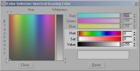
Blurry Refraction/Reflection Method (fR
Material)
finalRender offers two rendering methods for blurry reflections/refractions. A
fast raytracing method is used by default. Blurry refractions and reflections
won't be visible through blurry mirrors or refractions in this mode. If you
need to render, for example, a Blurry glass object in front of a blurry mirror,
you need to check the Accurate Option.
Warning!
When Accurate is checked, finalRender will render an unlimited (depends on the
maxi mum ray depth) bounce of blurry rays of blurry rays of blurry rays and so
on.
Relaxed Highlights (fR Material)
Relaxed specular highlights are a special way to render specular highlights in
finalRender. Usually specular highlights are added with the diffuse color of
the shader result. Some artists do not like this kind of compositing of
specular highlights. finalRender offers a different approach to "add"
specular highlights to surfaces. When enable is checked, the specular
highlights are "alpha layered" on top of the diffuse color of the
shader re suit. This removes any influence of the diffuse color when specular
highlights are drawn.
Amount controls the level of adding or alpha layering. A value of 100% will use
alpha layering only no diffuse color influence will be visible in the specular
highlight.
HDRI Cover Angle (fR Material)
Cover Angle influences the reflection of a HDR-Image only without influencing
any related GI effect. Increase this value to get a blurred reflection of a
HDR-Image. When using High Dynamic Range Images for Global Illumination you
might run into trouble when using extreme light probes. Please read the chapter
about "Using High Dynamic Range images for Global Illumination".
Self Illumination Multiplier (fR Material)
Standard 3ds max materials do not offer such a multiplier function. The self-illumination
Amount is restricted to 100, it is not possible to go above 100%
self-illumination. However, this is necessary when you want to create bright
reflections of virtual light sources, for example. This multiplier increases
the Amount of self-illumination of the material. High multiplier values will
result in brighter colors beyond the 255, 255,255 range of the clamped
rendering result.
Diffuse Multiplier (fR Material)
You might know this kind of option from the ONB (Onen-Nayar-Blinn) shader fads max. finalRender gives you this option for all
shades. The diffuse color component of the material may become much brighter.
Shadow areas are not affected by this option. Please keep in mind that high
multiplier values will affect Global Illumination.
Caustics & Global Illumination 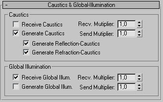
In the Caustics & Global Illumination rollout menu you'll find all settings
to control the Caustics and Global Illumination effects on a per material
basis. Each material may have individual multiplier values for sending and
receiving caustics or Global Illumination. You may also rum On or Off, Sending
or Receiving for each of the effects.
Receive Caustics (fR material)
Check this option to make the material respond to caustic light Photons. If
this is turned off you will not see any caustic effects on objects using this
material.
Important
You must also check the object's properties to enable caustics for specific
objects. Remember that Object properties always overwrite the material
settings!
Receive Caustics Multiplier (fR material)
Ibis multiplier value increases or decreases the intensity of the caustic
effect for objects using this material.
Generate Caustics (fR material)
Check this option to enable caustic effects created by objects using this
material. If this is turned off you will not see any caustic effects on objects
using this material.
Important
You must also check the object's properties to enable caustics for specific
objects. Remember that Object properties will always overwrite material
settings!
Send Caustics Multiplier (fR material)
The multiplier value increases or decreases the intensity of the caustic effect
for objects using this material.
Generate Reflection Caustics (fR material)
finalRender lets you decide if you wish to see caustic light patterns created
by reflections, refractions or both. Check this option to get caustic effects
created by reflections.
Generate Refraction Caustics (fR material)
Check this option to generate caustic light patterns based on refraction. The
option to decide if reflection or refraction is used for caustic effects is a
powerful feature Imagine a swimming pool for example, the water surface
reflects and refracts light, but with an outside scene you would not need to
calculate the reflective caustic patters as there would be nothing to receive
this effect. This saves lots of render time and helps keep the memory
management under control.
Receive Global Illumination (fR material)
When checked all objects using this material will respond to Global
Illumination. If this is turned off you will not see any Global Illumination on
objects using this material.
Important
You must also check the objects properties to enable Global Illumination for
specific objects Remember that Object properties always overwrite material
settings!
Receive GI-Multiplier (fR material)
A multiplier value that increases or decreases the intensity of Global
Illumination for objects using this material.
Generate Global Illumination (fR material)
When checked all objects using this material will generate Global Illumination
(transport light). If this option is turned off all objects using this material
will not contribute to the overall light transport in the scene.
Important
You must also check the object's properties to enable Global Illumination for
specific objects. Remember that Object properties always overwrite material
settings!
Send GI-Multiplier (fR material)
A multiplier value that increases or decreases the intensity of light transport
to other objects in the scene.
finalRender Local Settings 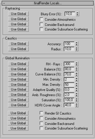
finalRender materials are intended to completely replace standard 3ds max
materials. For speed and quality you should use finalRender materials as much
as possible. Only finalRender materials offer the full control of all kinds of
raytracing effects. We also strongly recommend that you make heavy use of the
local finalRender parameters as it's the most effective way to get more
efficient rendering times.
Use Global/ Use Local Blurry Error (fR
Material)
Press this button to activate the local Blurry Error parameter. When this
button display "Use Local" all global parameters of this type are
disabled.
Use Local Blurry Error % (fR Material)
Diffuse or blurry re flections are very processing intensive raytracing effects
Blurry Error % controls the Amount of error allowed for a diffuse reflection
ray. If this parameter is set too high speckles or other kind of artifacts can
be created. Keep this value as tow as possible for the best rendering results.
Use Local Consider Atmospherics (fR Material)
If you want to see atmospheric effects in raytraced materials (reflections or
refractions) check this option.
Example:
A mirror object will reflect a PyroCluster(R) effect, a glass object will show
refracted atmospheric effects.
Use Local Consider Background (fR Material)
When turned off the refracted or reflected rays will not see the background
color or image.
Use Local Consider Subsurface Scattering (fR
Material)
Turn this option on to consider sub-surface light scattering in the Global
Illumination pass When off sub-surface light scattering is only considering
direct light sources.
Use Local Accuracy (fR Material)
Sets the Amount of Photons to be searched for by the finalRender caustic
engine. Higher numbers mean that more Photons will be collected be fore the
final light energy of a point on the surface is calculated.
Tip
Larger numbers tend to wash out the caustic effect.
Use Local Radius (fR Material)
This value is used whenever the radio button is checked. It defines the radial
area in world units for the caustic engine to look for Photons in space. Larger
numbers will create better more realistic images. As you can imagine though
searching in a bigger area and averaging such an area will take more time to
render! For fast renderings keep this value as low as possible.
Tip
You can tell that the radius value is too low as you will you start to see
single spots or splashes of lights where they shouldn't be. To get rid of this
increase the radius value.
Use Local RH-Rays (fR Material)
Random Hemispheric Rays (RH-Rays) are an essential part of Global Illumination
rendering. The Amount of RH-Rays is in direct relationship to the quality of
the final image. Assuming that the sample distribution in the scene is also
good enough, more rays will create smoother and better images. Rays are needed
more in scenes that have little or no direct light, e.g. self-illuminated
materials serving as a replacement for area lights. RH-Rays are fired in a
hemispheric dome like manner from each sample point. Ever single RH-Ray that hits another surface will create
another Random Hemispheric dome of rays and so on. This kind of ray avalanche
will only stop when the maximum diffuse bounce level is reached. This bounce
level can be adjusted in the raytracer controls.
Use Local Balance % (fR Material)
Controls the balancing between the Minimum Density and the Maximum Density. A
Balance % of 100 means that every shading point will be used to detect GI
specific data. Specific data maybe nearby objects, intersecting geometry and
contrast changes in illumination levels. You need to adjust Balance value
whenever you start to see missing parts that are not covered by samples or by
samples that are too big. A good example of this is when shadows are missing or
jagged.
Tip
Be careful, by increasing this value even in small amounts could result in a
explosion of total samples created by finalRender. You need to
"balance" all three parameters or the re suits could be frustrating.
Use Local Curve Balance % (fR Material)
Curved or bumpy surfaces are a classic killer for GI Imagine a surface with
small canyons, the lowest points of the surface will consume many RH-Rays and
many of them can't escape from this "black hole". Even worse, the
"near object detection" process runs crazy as it detects each ray
created for nearby object and then starts to create more samples to compensate.
To help you in avoiding these "black holes" we have added the Curve
Balance % parameter. Decrease this parameter to make the finalRender engine "blind"
to curvy or bumpy surfaces. For more details, read the chapter "The Curvy
Surface Problem".
Use Local Min. Density (fR Material)
Defines the minimum density to be used to place sample points in space. Each
sample point will be placed with at least with this distance to each other.
What distance is it%
The distance you are able to set with Min.Density is measured relative to the
scene boundary. So a really big scene also needs bigger Min. Density values.
Also be careful, if you remove an object some 100,000 units away, the scene is
suddenly only 500 units wide and if you kept the minimum density at 5000, you
could run into trouble because the density has increased by a factor f 2001.
Use Local Ambient Multiplier (fR Material)
Use this setting to globally control the indirect light level in a scene. Note
that increasing this value will not destroy the GI-Solution file. You may
change this value without the need to reset the GI-Solution as all indirect
light values are multiplied by.
Tip
It is much too easy to use this global setting to make your scene look nice. We
do not recommend this as a solution to get a dark scene brighter. Most of the
time this will reveal image artifacts. A better choice is to model the scene
with a natural distribution of direct light and use the Global Send and Receive
multipliers of the material instead!
Use Local Adaptive Quality % (fR Material)
Use this setting to activate the adaptive random hemispheric ray (RH-Rays)
creation. If this value is unequal to zero, additional rays will be created
whenever the algorithm detects that a illumination level is not correct. An
Adaptive Quality of 100% means that up to 10,000 rays are sent out per sampling
point. This amount of rays will be sent out in the worst case only: The image
quality increases with increasing amounts of Adaptive Quality.
Important
The algorithm needs to send out a minimum amount of RH-Rays to detect that new
rays are needed. For example, if RH-Rays is set to 3 rays and Adaptive Quality
is set to 100% the result would still be very splotchy. A reasonable amount to
start with is a minimum RH-rays setting of 64 rays but some scenes may need 128
or higher.
Ambient Roughness % (fR Material)
Our research showed that images look the best when there is a special kind of
noise visible. Such noise patterns tend to blend away the image artifacts
create d by the GI rendering process. The Ambient Roughness value defines the
amount of noise to be added in shadow areas or are as of high contrast. Higher
values will create more visible noise.
Use Local Saturation % (fR Material)
The Saturation parameter allows you to desaturate an image or even
over-saturate the colors of an image. If want more and stronger color bleeding
increase this value. If you don't like the colors turn it to aero.
Use Local HDR1-Cover Angle (fR Material)
Lets you control the lighting quality of an HDR-Image, some HDR-Images show an
enormous intensity range for each single pixel. Increase this value to reduce
the Amount of bright or dark spots in an image. To learn more about HDR-Images
see the chapter about High Dynamic Range Images.
Use Local Render GI-Caustics (fR Material)
Complex effects like caustic patterns created by refractive or reflective
objects are handled in one pass. Turn this option on to see caustic light
patterns. Please note that the rendering time will rise considerably.
Use Local Consider Atmospherics (fR Material)
When checked atmospheric effects will be considered in the Global Illumination
pass Atmospheric effects like combustion or volume fog maybe used as a real
volumetric light source in a scene. When turned on a large Amount of rendering
overhead is added to the render time.
Use Local Consider Background (fR Material)
Check this option to use a background image or a background color as a light
source, which will add some Amount of indirect light to the scene. If turned
off all rays hitting the background will be treated as if they had found a
black color.
Use Local Consider Subsurface Scattering (fR
Material)
Turn this option on to consider sub-surface light scattering in the Global
Illumination pass. When off sub-surface light scattering is only considered
from direct light sources.
Sub-Surface Scattering 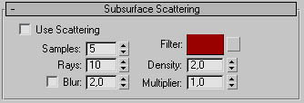
Sub-Surface Scattering describes a natural effect appearing on & in semi
transparent materials. Many more materials besides glass and clear liquids are
able to transport light through their volumes. finalRender introduces for the
first time real sub-surface light scattering to 3ds max. It allows you to
calculate volumetric light scattering in solid media, one great use of
sub-surface light scattering is the simulation of human skin! If you think your
skin is not "transparent" you'd be wrong. Put a bright flashlight
behind your finger, for example, and you can see a red color tone and you might
see your bones as a dark diffuse area "in" your finger. Ifs exactly
this kind of effect can be ray traced with finalRender. Remember as subsurface
light scattering is a real 3D volumetric Global Illumination process it creates
millions of samples in 3D space, which could take some time to render.
Illustration FR-15 is identical to illustration FR-16 except for the use of
subsurface scattering for the star object. The light source is inside the star,
which is why you only see black in illustration FR-15.
|
illustration FR-15 |
|
illustration FR-16 |
Samples SubSurface Scattering (fR Material)
Increase this parameter to get a more accurate space sub-division/sampling in
the volume of the object. Samples control the Amount of sub-divisions of the
"interior" light ray. The length of this interior ray represents the
density of the medium. A less dense object will allow the ray to enter much
deeper. The "interior" ray (dotted line in the illustration FR-17) is
evenly divided into sections. A Samples value of 5, for example, win divide the
interior ray into 5 parts. At each position along this interior ray the lights
energy is sampled (collected) and then spread through the medium.
illustration FR-17
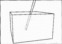
Rays Subsurface Scattering (fR Material)
Each sample point in space will also need to scatter light, this is done b sending out extra rays (see illustration ). The
Amount of rays per sample point can be set with this parameter.
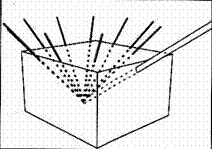
Filter Sub-Surface Scattering (fR Material)
You may set an individual filter color for the Sub-Surface Scattering effect.
When you want to simulate a human skin tone, you would set this to a red or
pink value. Together with the skin color you would get a realistic color mix
based on the thickness of the skin. An ear, for example, would appear much more
red as the skin is thinner and light transmits through it much easier.
Density Sub-Surface Scattering (fR Material)
Defines the thickness of the medium. Increase this value to reduce how much the
light penetrates into an object's surface. Lower values will make the object
more responsive to interior light scattering.
Multiplier Sub-Surface Scattering (fR
Material)
Increase this light multiplier to get a brighter interior light scattering
effect. This works in a similar way to the standard 3ds max light multiplier.
Note:
Both light amounts, the interior scattered light and the exterior lights are
added to the pixel values so it is very easy to burn out the effect by
inappropriate use of the Multiplier value.
finalRender Illustration Lines 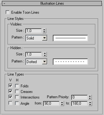
finalRender also offers a special non-photo realistic rendering mode to create
illustration and cartoon style renderings. Its main use is to create a hidden
line style rendering as you would from CAD applications. Hidden line renderings
have their own quality and expression values. Illustration rendering is
implemented as an interactive 3ds max render effect. To start creating an
outline rendering you need to add fRender Illustrator to the render effects menu.
Enable Toon Lines (fR Material)
Check this button to enable outline rendering for all objects in the scene that
use the render effect material.
Size - Visible Lines (fR Material)
Increase this value to get thicker outlines. The line si2e is based on pixels,
so a value of 2.0 will crate a line that is 2 pixels wide.
Pattern - Visible Lines (fR Material)
Choose any line style to draw the visible lines in the rendering. The icon on
the right next to the drop down list will display the line pattern to be used.
Size - Hidden Lines (fR Material)
Increase this value to get thicker outlines for all of the hidden lines. The
line size is based on pixels, a value of 20 will create a line that is 2 pixels
wide.
Pattern - Hidden Lines (fR Material)
Choose any line style from the drop down menu to draw the hidden lines in the
rendering. The line pattern is displayed right next to the drop down menu.
Folds - Line Tipes (fR Material)
Check the Visible box to enable the Fold lines for the visible part of the geometry
(as shown in illustration FR-18). To get hidden Fold lines rendered check the
Hidden box (see illustration FR-19).
|
illustration FR-18 |
|
illustration FR-19 |
Creases - Line Types (fR Material)
Check this box to enable the Crease lines for the visible part of the geometry
(shown in illustration FR-20). To get the hidden Crease lines rendered, heck the Hidden box next to it (see illustration
FR-21).
|
illustration FR-20 |
|
illustration FR-21 |
Intersections - Line Types (fR Material)
Check this box to enable the Intersection lines for the visible part of the
geometry (shown in illustration FR-22). To also get the hidden Intersection
lines rendered, check the Hidden box next to it (see illustration FR-23).
Note:
An intersection line is always created between two objects and these might have
different line styles for the intersection lines. As there can only be one
intersection line between two objects the line style can't be different, so
finalRender will always choose the intersection line style with the highest
priority (I being the highest priority). Use the Pattern Priority parameter to
assign a priority level to the intersection line style.
|
illustration FR-22 |
|
illustration FR-23 |
Angle - Line Types (fR Material)
Check the Visible box to enable the Angle lines for the visible part of the
geometry (shown in illustration FR-24). To also get the hidden Angle lines
rendered, check the Hidden box next to it (see illustration FR-25).
Note:
You can set an Angle range at which a line should be drawn. Use the from and to
parameters to control the range of angles a line should be drawn. This feature
is similar to the smooth modifier of 3ds max where the angle between faces
defines a smoothing group.
|
illustration FR-24 |
|
illustration FR-25 |
finalRender Illustrator Render Effect 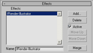
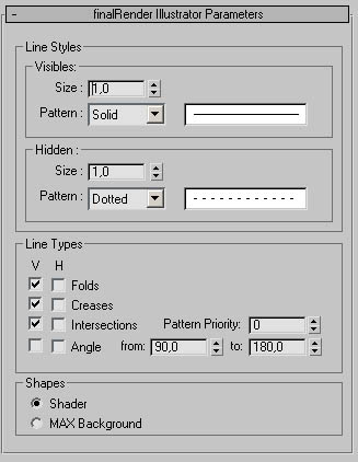
To use any of the illustration line functions described in the previous
chapter, a finalRender Illustrator effects entry must be added to the render
effects menu f ads may. The illustration rendered is an interactive
feature of finalRender that lets you adjust line settings without re-rendering
the whole scene over and over again. Note that some line types require a
re-rendering of the scene at least once. The finalRender Illustrator render
effect can be controlled in two ways. You may set the line parameters glob ally
through the Render Effects interface or set them on a per material basis The
line settings and parameters for the global and material sections are
identical, so we don't need to describe these settings again, check the
previous pages to learn more about these settings. There is, however, one
additional menu section in the Globals dialog that we need to describe in the
next chapter.
Shader/Max Background
Outlines can be drawn either based on the background color or straight on top
of the unmodified shader. Both styles have their advantages/disadvantages.
Using a white background creates renderings that took like classic technical
drawings. Enabling Shader with a combination of a Falloff material and with the
illustration outlines, creates an image with a classic cartoon look.
Illustration FR-26 uses MAX Background as an option and illustration FR-27 uses
the Shader setting.
Note:
This is not intended as a full-b town cartoon rendering system (yet)! It is
intended to create technical illustrations or sketch style drawings.
|
illustration FR-26 |
|
illustration FR-27 |
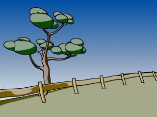
finalRender Material Converter
|
The full power of finalRender can be used only, when a finalRender
material is assigned to objects in a scene. Using the finalRender material
type adds the option to choose different Global Illumination settings or even
different caustic parameters on a per object/material basis. All the standard
material options are in the finalRender material so you do not give up
anything when you convert. Replacing standard 3ds max raytracing materials
with a finalRender material is strongly re commended. True raytracing effects
for glass objects or reflective materials will be much more efficient than
with the standard 3ds max material type. |
|
Refresh (fRMtlConvert)
Press the refresh button to update the list of materials, ads max does not pass
on material changes at all times. Occasionally you might need to press the
refresh button to get the latest list of material assignments in the scene to
appear.
Convert to find Render (fRMtlConvert)
Select any number of materials from the list above and press this button to
convert the selected materials into finalRender materials. All converted
materials will show up in the upper list of finalRender materials.
All (fRMtlConvert)
When activated, all materials in the list are selected.
Convert to Standard (fRMtlConvert)
Select any number of materials from the list and press this button to convert
the selected materials back to standard materials. All converted materials will
show up in the upper list of standard materials.
All
When activated, all materials in the list are.
|
finalRender tBaker Utility finalRender is intended to be the solution for all of today's
rendering tasks. To fulfill your highest expectations of finalRender we have
added lots of additional tools that will make your rendering life much
easier. tBaker is one of these amazing tools we would like to discuss in this
chapter. |
|
Pick Object
tBaker is able to create light and texture maps from many objects in one go.
Each object must be added by clicking on the Pick button and clicking on the
objects you want, or if you wish you may use the 'H' key to select multiple
objects in one go. All objects selected for processing in tBaker are listed in
the dialog shown to the right.
W Channel (tBaker)
Every object in the scene may have a different UV channel assigned. The quality
of the final result of tBaker is dependent on proper UV coordinates. Make sure
that all of the objects use the correct UV channel. The channel you set in this
dialog controls the "unfolding and wrapping" method to be used later
on, when the object is exported to a real-time application or when it's used
with a collapsed UV and material. This function is explained in more detail in
the tutorial section of this manual.
Example:
An object, a bottle, for example, uses two different UV channels, channel for
the glass part and channel 2 for the label part. The label uses a planar
projection and the bottle uses a cylindrical projection. To bake both materials
on this object into one bitmap you would add a third UV channel (3) with
cylindrical mapping, In tBaker you would use this 3rd channel to start the
baking process. The final result will be a single bitmap with both textures
merged together with correct perspective distortion.
U-Size (tBaker)
This controls the size and dimension in pixels for the U-coordinate. A value of
100 will ere ate a bitmap that is 100 pixels wide.
V-Size (tBaker)
Controls the size and dimension in pixels for the V-coordinate. A value of 100
will create a bitmap that is 100 pixels high.
Tip
When exporting to real time applications keep the bitmap as small as possible,
for rendering purposes you should use higher resolutions.
Object Vertices (tBaker)
This option will use each vertex of an object to get the color and illumination
information of the surface. Note that the quality of the final vertex map or
vertex lighting depends on the Amount of vertices that object has. More
vertices will mean a better representation of the actual map or illumination.
Check out the last chapter about Vertex Color maps!
Light Map (tBaker)
Check this option to create light maps. tBaker will output only the light map.
A straight naming convention is used to identify the bitmaps created by tBaker.
All bitmap names follow this syntax:
Objectname_[T for texture, L for lightmap] Frame number extension
Example:
Box01_T0000.jpg
This makes it easy to tell by the name what the bitmap should be used for later
in the real-time application.
Texture Map (tBaker)
Check this option to create texture maps, tBaker. Will output the texture reap
of the selected object(s) only. A straight naming convention is used to
identify the bitmaps created by tBaker. All bitmap names follow this syntax:
Syntax:
Objectname_[T for texture, L for lightmap] _ Frame number.extension
Light & Texture Map (tBaker)
Check this option to create light & texture maps in one go. tBaker, will
output the texture map and light map of the selected object(s) only. A straight
naming convention is used to identify the bitmaps created by tBaker. All bitmap
names follow this syntax:
Syntax:
Objectname_[T for texture, L for lightmap]_Frame number. extension
Example:
Box01_T_0000.jpg
Vertex Color (tBaker)
To use the vertex color information of an object heck this option. The object must have vertex colors
assigned or this option will not make sense. Please check the ads max online
manual for additional information about vertex colors and how they are handled
in 3ds max.
Texture Map Channel (tBaker)
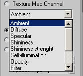
Check this option and select from the drop down list the map channel you would
like to bake. tBaker, will output the texture map of the selected object(s)
only. A straight naming convention is used to identify the bitmaps created by
tBaker. All bitmap name s follow this syntax:
Syntax:
Objectname_[DI for diffuse, for bump ... ]_Frame number. extension
Example:
ox0l DI_0000ipg
Object Surface (tBaker)
Choose this option to bake any texture applied to an object along with the
existing UV space. This option should only be used with objects that have one
material applied.
By Material-ID (tBaker)
When checked each material assigned to an object will be treated separately. If
an object has 20 material IDs for example, you will get 20 separate bitmaps out
of tBaker. Also each bitmap will have the same resolution as set in the U-Size
and V-Size parameters.
Collapse all Maps & UVs (tBaker)
Check this option to collapse a Multi/Sub Object material into one single
bitmap along with corrected and reassigned UV maps. This is one of the most
powerful features of tBaker.
Example:
Imagine an object has assigned a Multi/Sub-object material with 21 sub-object
materials. TBaker will collapse those 21 materials, along with the maps, into
one big rectangular bitmap. The U-Size and V-Size will be used as the maximum
size of the final bitmap. As a result you will get a bitmap with 21 equal
rectangular areas (shown in illustration TB-01). Such a massive reorganization
of the maps must also be represented in the UV coordinates of the object, r you won't be able to re-assign this new texture map
back onto the object When you use the Set Material function of tBaker, a
special modifier is added on top of the modifier stack of the selected objects.
Illustration TB-02 shows the unwrapped UV coordinates created by the tBaker All
inOnemodifier.
|
illustration TB-01 |
|
illustration TB-02 |
To Channel (tBaker)
Sets the target channel to be used be the All In One UV modifier of tBaker. We
recommend that you use always a different UV channel when assigning the tBaker
material If an object uses UV channel1, you should use UV channel 2 for the Collapse
Maps & UV function This will preserve the original LA/mapping of the
object.
Spaces in pix (tBaker)
Sets the space between the rectangular areas of the final bitmap. When you
intend to use the tBaker material with ads max and texture filtering (n the
material) it is strongly recommended to use a pixel space of at least 6 pixels
or you will see false colors or streaks in the rendering. The reason is that in
3ds max, filters on bitmaps need to average an area of pixels to get the final
color of a filtered pixel It's possible that neighboring pixels will be taken
into account for this filter operation. This is especially a problem with seams
or gaps in the UV space.
Filter Bitmap (tBaker)
tBaker renders all textures without any modifications, this means that the
textures are not filtered or in any other way processed. Usually this is the
preferred method when exporting such textures to game engines which have their
own filtering. However, you may also add a pre-filtering to the textures. A
value of zero will indicate no blurring and values above aero will blur the
textures.
Non Clamped Colors (tBaker)
Check this option to get the real pixels instead of the standard clamped colors
used by 3ds max. This option maybe used for special effects or to create high
dynamic range image. To read more information about High Dynamic Range Images,
check out the chapter on creating your own HDR-Images.
Animated Texture Maps
Single (tBaker)
Check this option to bake out the textures and light maps at the position of
the active frame.
Active Time Segment (tBaker)
Use this option to bake the textures and light maps in the given active time
frame.
Range (tBaker)
To set a specific time frame, activate this option and set the start frame and
(to) end frame the frame numbers of your choice.
Frames (tBaker)
When checked, you map assign any combination of frames to be used for texture
and light map baking.
Render Selected/Render All (tBaker)
You map choose to bake the textures or light maps of a selected object (from
the object list above) or from all objects in the list.
Map Manager (tBaker)
Click this button to open the Map Manager dialog.
tBaker Map Manager 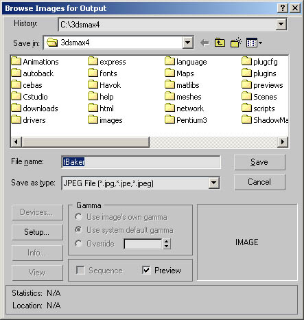
Click the MAP Manager button to specify the output path for all baked textures
or light maps.
Note:
You do not need to supply a filename, you may keep the suggested filename. The
directory path is used, only. All filenames for the textures and lightmaps are
created based on the names found in the ads max scene, see sample in the next
section. Bear this in mind as there will be no wanting message for overwrites.
File name Convention for tBaker
See sample structure below:
|
c:\3dsmax4\tbaker_Maps\untitled\ |
sphere01_T_0000.jpg |
Set Material (tBaker)
After tBaker has completed rendering the texture or fight maps, you may assign
them immediately to the object as a new tBaker material. This can be done for a
Selected object or All objects. Depending on the type of texture baking (Object
Surface, Material-ID...) an All in One UV modifier is added on top of the
object's modifier stack, ads max may not update the viewport correctly and the
new material assigned will not show up in the material editor automatically. To
display the new tBaker material in the material editor you will need to get the
material from the object in the scene. For more details about the tBaker
material see the description at the end of this chap.
Blur, Blur Offset and Filter Type (tBaker)
For your convenience we have added the texture filtering settings of the
material to the utility rollout menu. Before you Set the material (assign it to
the object after baking) you may choose any filter type and blurring factor.
Restore to Original Material
To get back to the object's original material you may choose one of two
options. You may reset a material of a Selected object or of All objects.
tBaker Material 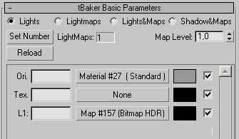
tBaker has a very special material type that handles light maps and texture
maps in way you would expect for a game engine. For example, a light map will
render in ads max fully self-illuminated and without any interaction of any
light sources in the scene. The great part about it is that you will still get
shadows cast onto such light mapped objects! This is a really great feature and
time safer when working with complex models. The tBaker material type works similar
to a multi/Sub Object material. One tBaker material can handle an unlimited
amount of light maps and texture maps if necessary.
Lights (tBaker Material)
Check this option to use the original material type (responsive to lights).
Light maps or texture reaps won't be used at all.
Light maps (tBaker Material)
When turned on light maps are used to represent the illumination. 3ds max light
sources do not add or influence the surface of the object!
Lights & Maps (tBaker Material)
Turn this option on to use the texture map and the lightmap together. 3ds max
light sources do not add to or influence the surface of the object.
Shadow & Maps (tBaker Material)
Choose this option to use the light maps and texture maps but let the 3ds max
light sources influence the surface with shadows. Shadows will be visible on
the object's surface but light will not influence the surface.
Set Number (tBaker Material)
Click this button to get the "Number of Materials" dialog. There you
may manually specify the amount of texture maps for this material type. This
works exactly like a Multi/Sub Material.
Reload (tBaker Material)
Click this button to force a bitmap reload for all textures in this material
This is useful when the texture has changed but 3ds max hasn't recognized the
change.
Map Level (tBaker Material)
Controls the output amount for the RGB values of the textures. Higher values
will make the texture or light maps brighter.
Material List (tBaker Material)
Here you can find the materials used as texture or light maps. The first
letters describe the type of the material. On means original material, if s the
material without the baked texture and baked UV . means texture map this is a baked texture map. L1 is
the first light map in this material.
Vertex Color Maps
What is a vertex color map?
tBaker offers a special proprietary method to store vertex information in
standard texture maps. A Vertex Color Map or Vertex Light Map is nothing else
than a bitmap in a special format that makes it possible to map each pixel 1:1
to a vertex of the same object that created this map. Vertex information is
stored in a straight forward non complex manner, so it's very easy to adapt the
method used by tBaker to any game engine on the market. Every pixel in a Vertex
Color map belongs to exactly one vertex of an object. The first pixel in such a
map is mapped to the first vertex of the object, the second pixel is mapped to
the second vertex of the object and so on. This format is very simple so that a
game developer may easily write a converter to transfer the vertex colors or
light data to any other format that their game engine can read.
Using these special Vertex Color maps in 3ds max is very easy tBaker offers a
special material type and texture map to handle vertex color maps. The Set
Material command will create and assign a tBaker material to the selected
objects automatically. This material will take care of all aspects of the baked
texture including new UV channels and Vertex Color information. This makes it
very easy and effective to check the quality and look of the baked texture.
The main idea behind this image format is that colors are stored along with
their intensity values. Usually bitmaps are stored as RGBA where each color
component is stored in the range between 0-255, the same is true for the alpha
channel. Images stored as RGB. A look fine on a monitor and they also look
great on a print out. However, when you intend to use such images in a
rendering application like finalRender you might find that there is a lot of
data missing to get good renderings.
One important piece of information that can't be found in a RGBA image is the
amount of energy each pixel has. This energy information is needed when an
image needs to serve as a natural light source in a 3D scene. Using images or
textures to replace a light source is called Image Based Lighting. The dynamic
range of an RGBA image is very limited and offers a poor quality to serve as a
natural light source. The maximum range an RGBA image may have is 255 for each
component; and this simply not enough to differentiate between light sources in
an image.
Any white pixel stored in a RGBA image could be a white car, wallpaper, the
sun, a 500-watt light bulb or even an atomic explosion! The advantage an
HDR-Image can offer is that instead of storing just RGBA components an
additional energy value is stored along with the pixels. This makes it possible
to differentiate between a white pixel and between other white pixels in an
image. By using a RGBA-E image format the rendering system knows the energy of
each pixel and so how bright that pixel actually is. A white pixel in an image
that has a value of 300, for example, would be a little brighter than a pixel
that is 255. If you found a pixel with a value of 10,000 you can assume that
this pixel does not belong to a "normal" surface or object in a
scene, but to a sky object or direct light source in the image that is
producing these high energies.
Bitmap HDR Texture Map 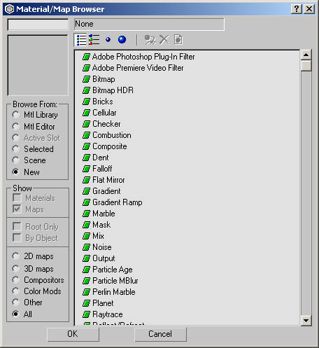
finalRender offers full support of HDR-Images along with their correct Non
Clamped Color values in bitmaps. As soon as finalRender is installed you will
see support for a new bitmap type called Bitmap-HDR, You must choose this
bitmap type to activate finalRenders advanced I mage Based Lighting functions.
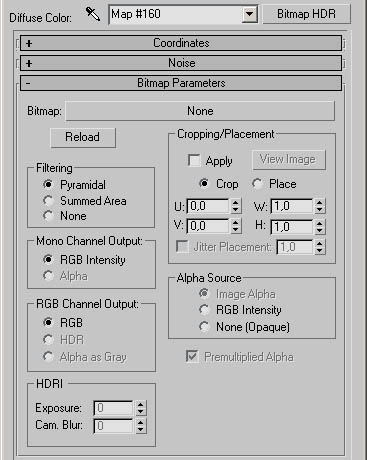
The new texture map type Bitmap HDR has only three additional parameters,
compared to the standard bitmap texture map. Find below the list of new
options.
RGB Channel Output (Bitmap HDR)
Here you will find the HDR radio button. Check this option to use the extended
data supplied by HDR-Images. If this is turned off (RGB selected) standard
clamped RGB values are used.
Exposure (Bitmap HDR)
HDR-Images include more information about each pixel than standard RGB images.
This makes it possible to calculate any exposure level for such an image. The
values range from negative (reduced brightness) to positive numbers (increased
brightness).
Increase this value to add some blur to the HDR-Image when seen from the
camera. This is useful when you plan to use the HDR-Image also as the
background image. Remember only the camera view is affected and not what the
Global Illumination rays are able to see.
Restrictions of HDR-Images
HDR-Images are sometimes tricky to use especially if you intend to use them as
the sole source of light in a scene. Even though finalRender offers one of the
most advanced algorithms to handle Image Based Lighting situations, it's still
a very processing intensive procedure to render a scene that uses only one
bitmap to illuminate it.
Scenes that use HDR-Images as replacement for light sources must be rendered
with full Global Illumination. This is the only method to get the correct
indirect illumination values from a surface (a modeled sky dome or
environmental sphere). We have discussed how HDR-Images offer a big advantage
over standard RGBA images, but for Global Illumination calculations this
advantage turns out to be the worst nightmare possible! finalRender uses
advanced stochastic methods to detect the various illumination levels in a
scene. Thousands of rays are shot randomly into the scene and each ray then may
or may not detect an illuminated point on a surface. The results from each ray
will be used to calculate the over all ambient (or indirect) illumination in a
scene, light must be "bounced" from other surfaces or there will be
no indirect illumination at all. Global Illumination in general has problems
with high contrast situations (like a small bright spot of light in a black
room). So at first non Clamped Color values look very useful but now the seem they're a big problem, keep on reading to learn
how HDR-Images work with Global Illumination.
HDR-Images are used in modern computes graphics to record natural light
situations. These kind of bitmaps are achieved by shooting several spherical
images of a real set or location at a different range of apertures, these
images are then turned into light probes (spherical HDR-Images). Now if you
want to re-create the exact lighting situation of that set you would then use
the HDR-Image as the sole source of light for your 3D scene. Each single pixel
in the HDR-bitmap has the correct energy information for the set and so
finalRender can tell if a pixel should act as an ambient light source or not.
Usually HDR-Images show extreme change in energy values between single pixels
(this is why we call them High Dynamic Range Images). One pixel may have an
energy value of 10 and another pixel right next to it may have a value of
10,000. This kind of shift in the dynamic range (change in contrast) would kill
the Global Illumination approaches we have implemented in finalRender. Such a
change of energy would le ad to very strange rendering results using Global
Illumination. The many rays sent out by finalRender using the many illumination
values from the HDR-Image would create a splotchy rendering, with lots of ugly
spots showing high or low brightness.
HDR-Images because of their nature, high contrast changes from pixel to pixel,
must be handled in a completely different way. This is why the finalRender
material and also the Global settings dialog offers a special parameter called
the HDRI Cover Angle. We recommend you make heavy use of this parameter when
you intend to use HDR-Images. Bigger HDRI Cover Angle values will reduce visual
artifacts in the rendering caused by the high dynamic range values in the
bitmap. finalRender uses this proprietary method to solve the stochastic
ray-shooting problem that every Global Illumination system has when using
HDR-Images as textures. This function is very effective in keeping the amount
of Hemispheric Random rays down.
We recommend that you check out the sample HDR-light Probes that came with
finalRender. To load those images in to the virtual frame buffer (see
illustration to the right) go to FILE-View Image File and choose HDR as the
file format. When an HDR-Image is loaded into the frame buffer you may check
the pixel rabies by holding down the right mouse button and by moving the mouse
around. Each color of a pixel is displayed in the dialog that opens up. Keep
the right mouse button pressed to see constant updates of the Non Clamped Color
values. You will be surprised how fast those values change, even in plain white
areas.
Quick Tutorials
finalRender Object Lights
Under the create lights pull down, you will find the option for finalRender
lights. There arc two options listed, fRObjLight and fRPartLight Both of these
options will embed lighting into geometry - one is for standard 3D objects and
the other is for par tick systems. Let's take a look at how they work. You an find the tutorial files under
3dsmax\scenes\cebas\fimlRender\tutorials.
Step 1
First, create a box and turn it inside out make it 100x200x50 units. Add the
modifier "normal" and check flip normals. Then create a target camera
from the top view and point it at one corner pointing at the other. Use the
move tool to raise the camera from the ground.
Step 2
Now, create a teapot near the corner that the camera is viewing. Create a tours
near the wall. Apply a red plastic material to the teapot and a white matte
material to the walls. Apply a self-illuminated checker material to the tours -
make the checker pattern use U offset of 5 with tiling, and V Tiling set to 4.
The checker colors an be anything but I used green and blue to contrast
with the red teapot. Load scene file luma01.max if you want to start at this
point.
Step 3
Rendering at this point will yield a simple image, be cause Max default
lighting is illuminating the room. Click on create light in the tab panel and
pull down the option for finalRender lights. Then lick on fRObjLight. At this point, fR is waiting for
you to click on a valid 3D object in the scene. Click on the teapot If the
teapot object name does not appear in the fR object list you can use the pick
button to reselect it If you render at this point, the image will be black
except for the self-illuminated tours. The presence of the fRlight will cause
the default lights to go away. But the fRObjectLight has not been set to create
or even reflect.
Step 4
Switch to the modify panel and make sure the fRobject (which is probably called
Teapot_LO01 is selected. Check the self-light option to cause the teapot to
glow red But don't render just yet. By default, an emitter is placed on every
face of the object. To see that, go to the attenuation panel of the fRObjLight
parameters, and check the U (for use) and S (for show) on the far attenuation
section. You should see many yellow and orange lines appear. The full soft light
created by Luma does not require so many emitters, and the more emitters you
use, the slower your scene will render. To reduce the number of emitters used,
set the face reduce parameter to 16. Now when you render you should get a fast
result of a glowing red room interior with a black teapot. The teapot emitters
do not light the teapot - they point outward.
Step 5
Let's change our intention with this fRObjLight Let's use the teapot in a light
reflecting mode to make the teapot create red light only where it is struck by
other light. Uncheck the self-light box and check the reflect box to allow at
least one bounce between multiple fRObjLight. Then create an omni light of
strength 180 near the teapot, on the left side as viewed from the camera. Turn
on its shadow casting checkbox. You should see the red color of the teapot
splash back only from the sides of the teapot which are illuminated. Load
Luma02.max if you wish to jump to this point.
Step 6
Now apply another fRObjLight, this time to the tours. Checkbox the self-light
option and again enable the Use and Show options for far attenuation to see the
emitters on the tours. Set the falloff start and end to 40 and 80 units, so
that you can see the lines. Now lets us LTV mapping to place the emitters. Checkbox
the use UV with channel set to 1. Then set the U lights to 4 and the V lights
to 16. Now each stripe of the tours has two emitters across by 4 emitters
around (the cross section of the tours). Rendering now yields a spotty result.
Set the S Distance and S Attack up to 6.0 to help spread the light more quickly
as it leaves the emitter. Also set the Luma angle to 120 to make the emitters
spread light more broadly. Finally set the multiplier to 2 for a stronger
effect. You can load Luma03.max to see the tendered result at this point.
Step 7
Next, create a super spray particle emitter in the left viewport. Raise the
emitter above the ground, and angle the emitter to spray towards the camera.
Set it to show 100% of the particles, and set the rate to 3, the speed to 2 and
the speed variation to 10%. Also set the stop and lifespan to 100, with
variation of 25%. Set size to 2, and grow and fade to 0. Particle type is
sphere. Assign a white, fully self-illuminated material to the particles, and
make it 99% opaque with additive transparency.
Step 8
To make these particles move nicely, let's add two space warps. Create a
gravity space-warp (under forces) in the top vie w (so that it points downward)
and then create a UDeflector (under deflectors) and click its pick object
button and choose the room box object. Set the UDeflector parameters to 0.6 for
bounce with variation of 5%, chaos at 5% and friction at 5%. This will cause
the spheres to scatter and also slow down as they bounce around the room. Load
Luma04.max if you want to start at this point. Now create an fRPartLight and
click on the particle emitter. It should show the Super spray particle system
in the "pick particle system" area of fRPartLight's dialog Go to the
modify panel to further adjust the fRPartLight parameters. Set the angle to 180
and enable the Use and Show attenuation options. Circles should appear around
all of the particles. If not use the minimize/maximize window button (hotkey W)
and the falloff circles should appear. Set the FAR start and end falloff to 10
and 40 units. You will also nearly always want to set the angle to 180 for
maximum particle area lighting. Render and you should see each particle
emitting light. Load Luma05.max to see the final result.
A tour of the features of fRShadows
finalRender adds two new types of shadows to ads max - the fRShadowMap and
fRSoftShadows. The sample scene can be found under:
X:\3dsmax4\scenes\cebas\finalRender\fr_Volume Light\tutorial
The file is called "tutorial end.max".
fRShadowMap
fRShadowMap is an enhanced version of the standard max Shadow tap. It can
create colored shadows from semitransparent objects. It offers the ability to
simulate soft shadows by intelligently blur ring a standard mapped shadow. It
also offers pre-rendering of the shadows, which can save time on scenes with
fixed lighting - the shadows do not need to re-render for every frame. With
this type of shadow, the shadows must always be pre-rendered. Let's explore
this shadow type.
Step 1
Create a 32 radius teapot on a 400x400 plane. Give the plane a white material,
and the teapot a shiny bright blue 2-sided material. Cast a targeted spot light
on the teapot, and enabled standard 'shadow map' shadows, so that the spot
casts shadows from the teapot on the plane. Adjust the perspective view so that
you can see the scene and the cast shadows clearly. For comparison, render a
frame.
Step 2
In the shadow parameters rollout of the Spotlight, use the pull down to select
fRShadowMap. To get similar results to the standard shadow maps, you need to
set the map size to 512 in the fRShadowMap parameters rollout. The default is
256. Now, if you render, you will see no shadows. They must be rendered first.
In the Map creation section of the fRShadowMap parameters area, bring up the
map manager and choose change path; make sure this is pointing to a legal
folder. The general storage point is under your max directory in a folder
called shadow maps. Close this dialog. Make sure the Map Creation frame range
is set to "Single," and click the render button that appears in the
fRShadowMap parameters dialog. The rendered dialog will pop up for a few
seconds while the shadow is rendered from the light source. Now this shadow map
is saved and assigned. If you render your perspective view with max's render
button, you'll see your new shadows, and you'll notice there is no shadow pass
for the rendered.
Step 3
Now lets explore some of the fRShadowMap features. In the material editor,
change the teapots material: set its opacity to 25% and set the Filter Color
(under the Extended Parameters rollout for the material) to the same blue color
as the diffuse color. Render the perspective view - you'll notice the shadows
arc still black. That's because you must re-render the shadow to get it to
update the shadow map that is being used. Go back to the light parameters and
click the render button in the fRShadowMap Parameters rollout to replace the
shadow map, and then re-render the perspective view. Now you have colored shadow
maps. If you were creating an animation where the lights or shadow casting
objects move or change color properties, you would use the map creation rollout
to create the entire frame sequence.
Step 4
Next, enable the "Use" checkbox in the
fRSoftShadows
For true soft shadows, the fRSoftShadows option allows true raytraced penumbral
shadows. Penumbral shadows are created when the light source is larger than a
point. This option wall allow a light to cast shadows as though it were a
circle or rectangular area light source. Enable fRSoftShadows by choosing it in
the shadow pull downs under the light's Shadow Parameters rollout. Now page
down to the fRSoftShadows Parameters rollout If you render now, you'll get
black shadows again, even though the teapot material remains transparent To
avoid this, go to the fRSoftShadows Parameters rollout and set the "lire
Transparency" checkbox. To get faster rendering for testing, bring the
Surface Samples down to 8 for Min Samples and 64 for Max Samples. This will
cause a stippled appearance to the shadows, but the values can be set higher to
get rid of this effect after adjustments are made. Now, set the radius to 8 and
re-render. You'll notice that the shadows be come softer as the distance for
the shadow ray increases between the shadow casting object and the shadow
receiving object.
Fast Volumetric Lights
Now, set the shadow type back to fRShadowMap mode, and you'll notice all the
values are reset to the defaults. Hide the ground plane object. Render the
shadow map as be fore. Now go to the bottom of the spot light dialog, and look
at the "Atmospheres & Effects" rollout. Click Add and choose
fRVolumeLight-Effect, make sure the word Effect is at the end of the entry.
This is the post-processed volumetric light effect, and is very fast. Now,
click the fRVolumeLight-Effect entry in the Atmospheres & Effects and set
the density to 1. Before rendering, you may need to zoom out and get under the
teapot somewhat for a good side view of the light beams passing through the
teapot. When you click render, the teapot will render quickly, and then in a
second pass, the volumetric effect will appear with a blue tinted shadow in the
fight that passes through the teapot. If you now click the interactive checkbox
in the Preview sec ton of the Render Effects dialog, the rendering will
recomputed. At this point you may adjust the light position and get very fast
feedback in the rendered view. There is an atmospheric equivalent of the fR
volume light also, for true 3D volumetric effects. In most
cases the post processed version will suffice.
Creating Caustics
Unhide the ground plane. Delete the fRVolumeLight Effect at the bottom of the
Spot Light parameters. Now we'll set the clear blue teapot to cause caustic
effects on the ground plane.
Step 1
First we need to enable caustics. Globally, this is set in the finalRender
Globals. Bring up the Globals and in the Caustic Parameters rollout, set the
Enable Caustics checkbox to on, and set the accuracy to 20 and radius to 2.
This will cause caustic effects that look like spots of light, but the radius
can be raised later to blur out the caustic effect. Next, the teapot needs to
be set to generate caustics - to do this, select the teapot and right click on
the teapot, and choose properties. In the mental ray settings at the bottom
left of the dialog, enable the Generate Caustics checkbox. Close the properties
dialog and select the spot light. In the modify panel, you'll find a rollout
for the spotlight called Indirect Illumination Params. Here you can set the
number of caustics photons. Set this to 1000 as a starting point, for fast
rendering. Finally, you must at minimum have a material in the material editor
that is the finalRender material type, thought it need not be assigned to any
object. Pick an unused material slot and set the type to finalRender. Go ahead
and render, and at this point you should be able to see very soft blue caustics
spots around the teapot - the caustics photons.
Step 2
To have greater control over the caustics effect, the materials in the scene
need to be finalRender material types. You don't need to carefully recreate
finalRender versions of the materials you used in your scene, because there is
a utility to automate the process. Bring up the utility panel and click the
More.. button. Choose fRMtlConvert and you will see the materials used in your
scene under the Standard Materials list. To convert them, simply select them
all (there is an All button at the bottom of the list for selecting all) and
click the Convert to finalRender button. You should see the material move to
the bottom listing. Now, bring up the material editor, and you'll notice that
the previously active materials are no longer active in the scene. Use the
material editor's eyedropper tool (to the left of the material name) and click
on the teapot, to get its new current material. You can see that it is a
finalRender material type. Set all of the caustics checkboxes (in the material
editor rollout Caustics and Global Illumination) and set the send and receive
multiplier to 5.0. Do the same for the floor material, but do not check the
generate caustics checkbox - this object is not transparent. Now render again
and the spots will be much more intense. Experiment with the number of caustics
photons (in the spotlight parameters) and the radius (in the finalRender global
Caustics section) to get smoother effects. You'll find that there is a tradeoff
between quality and render time but if you start with a crude, fast effect you
can ramp these values up for a good result with minimum render times.
Cylindrical Lights
finalRender offers a cylindrical light source, with all the other parameters
you are used to from spot and omni lights. You create a cylindrical light just
like the cylinder primitive - drag a circle and then lift the mouse button and
move the mouse to set length, then click to finish. In the scene we created
before, let's delete the spotlight. Neat, disable the caustics effect in the
finalRender global. Everything else can stay the same, the finalRender
materials won't cause any slower rendering or other complications. Go to the
create lights section of the command panel, and use the pull down to select
finalRender lights. Choose Cylinder Light. Create a cylindrical light of radius
5 and length 200. Lay the cylinder on its side, and place it near the teapot,
above the floor somewhat higher than the teapot. Set the perspective view so
that you can see both the teapot and the cylinder light. In the modify panel,
with the cylinder light selected, check the render mesh checkbox, set diffuse
angle to 20 and hotspot to 98. Make sure that shadow casting is turned on and
render. You should see the result of a cylindrical light. The shadow is of
course like that from an omni light since we arc using standard shadow maps. If
you want, you can set the shadow type to fRSoftShadows to get a result more
like this light type would create in reality Turn on the Use Transparency check
both, since the teapot is clear blue. Set the Area type to Warped Rectangle.
You can set the width to 10 and the height to 100 to approximate the shape of
the light source. For faster rendering, you may tower the surface samples to 8
min and 32 max while editing the shadow effect. Note that with soft shadows,
the cylinder mesh may interfere with the calculation, so set the render mesh
option for the cylinder light back to off. Render to see the result, and adjust
the surface samples back to 16/128 for a high quality rendering.
Glossar
Object Light Emitter
These emitters are objects with an attached finalRender fRLightObj helper, with
self-light or self-illumination turned on. These objects act as a light emitter
like any other light object in 3ds max or 3D STUDIO VIZ. The light color is
taken from the object's surface or it can be overwritten by the color dialog.
Object Light Reflector
An object light reflector is an object with an attached finalRender fRLightObj
helper with self-illumination turned off. All light hitting the objects surface
is reflected and the light color is taken from the object's surface. This
feature is very useful to simulate Radiosity like effects.
AABS
Abbreviation for Automatic Analytical Binding System, AABS is a proprietary
modeling tool created by cebas Computer. It lets you assign various kinds of
special effects to an object by directly clicking onto it in the viewport.
Intersection Point
Is a point in 3D (or 2D) space where two lines or triangles meet or intersect.
In the case of a raytracer it describes the point where an eye ray intersects
with a triangle surface.
Shading
Each point on an object's surface has to get a certain color value. This color
value can be "created" in many different ways. A point on the surface
can get brighter from the influence of light or even by a simple formula. The
process of calling the functions to calculate the color of the surface point is
called shading.
Shaders
A raytracing/rendering system might use many different formulas to calculate
the color of a point on an objects surface. The "method itself to render
specific effects is called Shader. You might have heard from Fur Shaders, Water
Shaders or Volume Shaders.
Sharing Point
After preparation of the scene by the core engine of the rendered, the
rendering begins by calling all the Shaders for each visible point from the
camera view. Those screen pixels are called.
Random Hemispheric Rays
Global Illumination can be rendered in many different ways, one common way is
to send out extra rays from each shading point, into the scene to detect the
"real" illumination level. To get the best coverage of space
possible, the rays are sent out randomly in random directions. Usually these
rays will span a hemisphere starting at the shading point.
Global Illumination
Describes a raytracing-based approach to render indirect illumination by
sending out extra rays, from each shading point. The results collected by those
extra rays are averaged and one final illumination amount will be added to the
ambient value of the shading point.
Radiosity
Is an alternative method to render correct illumination levels in a 3D scene.
Radiosity is a pure energy based light distribution system that needs to
calculate "all" surfaces in a scene before an accurate image is
created.
Rendering
Creating an image with pure virtual 3D data is called rendering. Several
algorithms and methods are available but basic ally rendering means: "DRAW
A NICE IMAGE"
Photon(s)
Small light particles that transport the energy in a 3D scene. Rendering
software usually works with a particle model to describe the world of light
bouncing around.
- Main
- installation 2
> authorization 3
- finalRender 4
> Global Illumination 6
> Caustics 8
> System related restrictions 10
> The Curvy Surface Problem 11
> Good news, light is scattering! 12
> Optimizing a Global Illumination calculation 13
> Other ways of optimizing 16
> Conclusion 16
- New finalRender Light Types 18
> finalRender Object Lights 18
> Particle Light 35
> Cylinder Light 38
- finalRender Shadow Types 42
> SoftShadow 43
> Color Shadow Maps 48
> Shadow Map Handling 53
> Shadow Map Manager Dialog 55
- What is a Caustic? 57
> Volume Caustics 58
> Let s start doing Caustics 59
> Caustic Material Settings 61
> Indirect Illumination Params 63
> Volume Caustic Interface 64
- Volume Light Effects 66
> How to access fRVolumeLight 67
> Volume Light Parameters 68
> Atmospheric Shadows 72
> Volume Light Attenuation 74
> Volume Caustics 75
> Volume Light Color Parameter 76
> Volume Light Fall Off 79
> Volume Light Noise Params 80
- finalRender Global Settings 81
> finalRender Globals Menu 82
> Global Illumination Parameters 84
> Animated Global 87
> Advanced Settings 90
> Raytracer Parameters 92
> Caustic Parameters 94
> Camera Effects & Anti Aliasing 96
> MSP Parameters 99
> Material Type: finalRender 100
> Material Settings 101
- finalRender Parameters 102
- Advanced finalRender Parameters 107
- Caustics & Global Illumination 119
- finalRender Local Settings 120
- Sub-Surface Scattering 125
- finalRender Illustration Lines 128
- finalRender Illustrator Render Effect 133
- finalRender Material Converter 136
- finalRender tBaker Utility 138
> tBaker Map Manager 143
> tBaker Material 144
> Vertex Color Maps 145
- High Dynamic Range Images 146
> Bitmap HDR Texture Map 147
> Restrictions of HDR-Images 149
> High Dynamic Range Images and Global Illumination
- Quick Tutorials 151
> fRShadowMap 153
> fRSoftShadows 154
> Fast Volumetric Lights 154
> Creating Caustics 155
> Cylindrical Lights 156
- Glossar 157
- Index 159
|